


NOMENCLATURE
Abbreviations and Acronyms
- AEA
All Electric Aircraft
- AGILE
Aircraft 3rd Generation MDO for Innovative Collaboration of Heterogeneous Teams of Experts
- A.P.U.
Auxiliary Power Unit
- CFD
Computational Fluid Dynamics
- CIAM
Central Institute of Aviation Motors
- CPACS
Common Parametric Aircraft Configuration Schema
- DLR
Germany Aerospace Centre
- ECS
Environmental Control System
- EPGDS
Electric Power Generation and Distribution System
- FCS
Flight Control System
- G
Generator
- HPGDS
Hydraulic Power Generation and Distribution System
- IFE
In-Flight Entertainment
- IPS
Ice Protection System
- LG
Landing Gear
- M
Motor
- MDA
Multi-Disciplinary Design Analysis
- MDAO
Multi-Disciplinary Design Analysis and Optimization
- MDO
Multidisciplinary Design Optimization
- MEA
More Electric Aircraft
- MTOM
Maximum Take-Off Mass
- OBS
On-Board Systems
- OEM
Operating Empty Mass
- PS
Propulsion System
- RJ
Regional Jet
- SFC
Specific Fuel Consumption
- SFCMCR
Specific Fuel Consumption at Max Cruise conditions
- SMRJ
Short- to Medium-Range Jetliner
- TLARs
Top Level Aircraft Requirements
1.0 INTRODUCTION
The power matching of Propulsion System (PS) and On-Board Systems (OBS) is having even more importance in aircraft design because of the continuous research for a competitive and less expensive aircraft. In particular, the PS and OBS have to be optimized together to achieve a further reduction of aircraft mass and fuel burnt in comparison to present day aircraft, as showed in(Reference Prakasha, Boggero, Fioriti, Aigner, Ciampa, Anisimov, Savelyev, Mirzoyan and Isianov1, Reference Prakasha, Della Vecchia, Ciampa, Ciliberti, Charbonnier, Jungo, Fioriti, Boggero, Mirzoyan, Anisimov, Zhang and Voskuij2). In addition, during the last decades, the OBS are improving using new technologies that aim to achieve the All Electric Aircraft (AEA) or – at least – the More Electric Aircraft (MEA) concepts. Some examples of application are given in(Reference Berlowitz3, Reference Jones4, Reference Chiesa, Farfaglia, Fioriti and Viola5). In general, the main aim is to replace the hydraulic and pneumatic systems with the equivalent electric ones. This should increase the ease of OBS monitoring, the integration among them, their efficiency(Reference Cronin6, Reference Scholz7) and the whole aircraft safety level(Reference Chiesa and Fioriti8) In particular, the removal of engine bleed air system reduces the aircraft mass by eliminating ducts, valves, heat exchangers and other heavy and maintenance-intensive equipment. The potential contamination of the cabin air supply with engine oil is also eliminated(Reference Cronin6). The systems electrification can be pursued in different ways using different technologies. Therefore, a great number of new OBS architectures (some examples of architectures are showed in(Reference Chakraborty and Mavris9, Reference Fioriti, Boggero, Corpino, Isyanov, Mirzoyan, Lombardi and D’Ippolito10) are now available for each designed aircraft, giving the designer more freedom in OBS architecture design than in the past.
The OBS electrification provides an elimination of the pneumatic power required to the engine, producing a beneficial effect on engine propulsive efficiency. The bleed air from the engine compressor is no longer required, and all internal high-pressure air is used to produce thrust(Reference Sinnet11). This should reduce the engine specific fuel consumption (SFC), thus reducing the fuel burnt for each unit of thrust produced. However, for MEA and AEA architectures, the pneumatic power is still necessary to supply the Environmental Control System (ECS) and other pneumatic equipment. For this reason, some dedicated electric compressors are installed requiring more power from electric generators. Therefore, the removal of bleed air comes together with a necessary increase in mechanical power offtakes. The effect on PS is a reduction of the stability margin of engine compressor(Reference Cronin6, Reference Lupelli and Geis12), other than a relatively low increase of engine consumption.
Therefore, considering the different OBS architectures selectable and their different influences on PS, the estimation of the engine performance variation is significant as well as the final effect on aircraft performance and mass. To perform this investigation, a multi-disciplinary design analysis (MDA) that involves at least OBS design, PS design, aircraft masses and performance estimation is necessary.
The main aim of this paper is to investigate the optimal OBS and PS power matching for a Regional Jet (RJ) and a Short- to Medium-Range Jetliner (SMRJ) performing an MDA with different OBS architectures. The study proposed in this paper is carried out employing a distributed collaborative Multi-disciplinary Design Analysis and Optimization (MDAO) environment developed within the Horizon 2020 AGILE project(Reference Project13), which includes models for the main aerospace disciplines such as aerodynamics, airframe, PS and OBS design. Parameters such as fuel efficiency, system masses and increased aircraft performance are considered as efficiency assessment criteria. Compared to other frameworks such as PrADO(Reference Braunschweig and Program14), VADOR(Reference Alzubbi, Ndiaye, Mahdavi, Guibault, Ozell and Trepanier15), OpenMDAO(16) and the Dakota project(Reference The17), the MDAO environment used points to the collaborative methodologies of the 3rd generation MDAO(Reference Ciampa and Nagel18). The collaborative methodologies aim to enhance the integration between disciplines and disciplinary experts. In the 3rd generation MDAO, the disciplinary experts are always involved during the analysis monitoring, interpreting and validating the results obtained from time to time. In this way, the results tend to be more accurate and correctly interpreted.
Concerning the paper subject, several studies have been carried out by researchers focusing on different OBS architectures(Reference Chakraborty and Mavris9, Reference Prakasha, Ciampa, Boggero and Fioriti19, Reference Fioriti, Boggero, Corpino, Isyanov, Mirzoyan, Lombardi and D’Ippolito10). However, these studies are not focused on OBS and PS integration, they are limited to one reference aircraft, and do not give any trend with aircraft class and mission requirement. To fill this gap, the focus of this paper compares the power matching of OBS and PS of the aircraft with different mission ranges and dimensions. This would ease the selection of most suitable OBS architecture for the different aircraft segments.
In the second section of the present paper, a brief introduction to the MDAO workflow developed in the framework of the Horizon 2020 AGILE project is provided. In the third section, the aircraft used as test cases have been described together with the results of the OBS and PS analyses. Finally, in section four, the difference between the two aircraft segments has been studied trying to define a possible trend in OBS and PS power matching.
2.0 DESCRIPTION OF THE MDAO WORKFLOW AND DESIGN SPACE
In order to analyse the effect of the OBS electrification on the PS performance to seek the best power matching, the MDAO workflow set up within the AGILE research project has been used. The workflow is depicted in Fig. 1 showing the partners involved, the disciplines exploited and how the disciplines are related to each other. This workflow is geographically distributed, and each competency remains in the partners’ computer avoiding intellectual property rights issues. This is one of the specific characteristics of the proposed workflow. Additionally, the disciplinary experts involved can supervise and control the functioning of their own modules. This should improve the reliability of the results and increase the possibility to perform specific investigations that involve a subset of disciplines (as the study presented in this paper). All these characteristics are specific features of the 3rd generation MDAO. The disciplinary modules of the present workflow are connected by means of the common XML-file called CPACS (Common Parametric Aircraft Configuration Schema) developed by the Germany Aerospace Centre (DLR)(20). Each disciplinary module can read the inputs coming from the other modules and write its outputs by means of this common file.
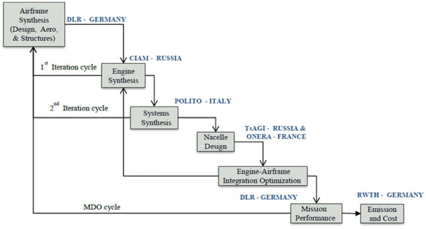
Figure 1. MDAO workflow developed within AGILE research project.
As shown in Fig. 1, the proposed workflow takes into account aero-structural design, PS design, OBS design, nacelle design, aircraft performance simulation, aircraft emission and cost analyses. As the aircraft design is an iterative process, the workflow iterates until a converged aircraft Maximum Take-Off Mass (MTOM) is reached. The MDAO starts from the preliminary design of the aircraft, which defines the aircraft structure, geometry and its aerodynamic performance. For this purpose, the tool VAMPzero(21) is initially supplied with only the Top Level Aircraft Requirements (TLARs) such as aircraft range, cruise speed, take-off and landing length. After the first iteration, the workflow updates fuel, engine and OBS masses starting from the results of the subsequent modules providing a converged and more reliable aircraft synthesis that includes the aircraft masses, main dimensions and aerodynamic coefficients. The second module calculates the PS performance (i.e. SFC, fuel flow, engine thrust) and other engine characteristics in terms of dimensions and masses. In Table 1, the input and output of the PS and OBS modules are listed to better explain the mutual interaction of these disciplines and their interaction with the other design disciplines. During the first iteration of the MDAO, the main inputs necessary for the PS module are the basic thrust requirements for each mission phase calculated by Airframe Synthesis module. After the first iteration, the PS module acquires the OBS power offtakes and more detailed thrust requirements are calculated by the Mission Performance module. Moreover, the PS module is also able to consider the nacelle geometry to take into account the change of engine performance due to its installation on aircraft. A first internal iteration cycle (see Fig. 1) between Airframe Synthesis and PS modules is established to speed-up the convergence of engine mass.
Table 1 Main input and output of PS and OBS disciplinary modules
At the end of this process, the OBS design is provided. All the main OBS such as flight control, fuel, environment control, avionics, landing gear, ice protection, electric, pneumatic and hydraulic power generation and distribution systems are individually designed. Considering the detail level of the analysis and the variety of the design parameters of the OBS, the inputs of OBS module include aircraft main masses and geometries as well as engine performance and mission profile (see Table 1). The main results are volumes, masses and power requirement of each OBS(Reference Boggero, Fioriti, Corpino and Ciampa22). A second internal iteration cycle is organized between the first three modules. In this way, the convergence of the OBS masses and main aircraft masses is accelerated. In this way, the next modules (in particular, Nacelle Design and Engine-Airframe Integration Optimization) that require more computing time start with more converged inputs reducing the overall MDAO time.
The nacelle geometry and the quantification of its integration effects on the engine and airframe are carried out using specific CFD analyses. In particular, using SEGOMOE optimization algorithm(Reference Lefebvre, Bartoli, Dubreuil, Panzeri, Lombardi, D’Ippolito, Della Vecchia, Nicolosi, Ciampa, Anisomov and Savelyev23), different variants of nacelle geometry and position are evaluated using Reynolds-Averaged Navier–Stokes calculations with shear stress transport model of turbulence. The effective thrust losses are used as objective function. Therefore, after the Nacelle Design and Engine-Airframe Integration Optimization modules, new installation coefficients are included in the workflow together with new pylons and nacelles masses.
The aircraft mission performance is calculated by means of Breguet range equations with the primary objective of quantifying the fuel used by the aircraft to perform the desired mission. All data concerning the masses (e.g. OBS, engine, nacelle and fuel mass) and performance (e.g. OBS power required, PS performance and nacelle integration coefficients) are used by VAMPzero to redefine the preliminary design of the aircraft. The described design loop is reiterated whilst the design is converged. Finally, the aircraft emission and cost are calculated by specific tools(Reference Lammering, Franz, Risse, Hoernschemeyer and Stumpf24). However, this last module is not used in the present work, since the difficulty to predict reliable cost and emission of innovative OBS.
2.1 PS and OBS design modules
Considering the focus of the present paper, it is useful to provide a more detailed description of PS and OBS modules. The PS module uses a detailed engine model based on the commercial software GasTurb v.12(Reference Kurzke25). The engine model is built around the maps of real engine components. An automatic bleed air handling is used to control the compressor surge margin discharging some compressed air into the bypass duct. This feature is particularly useful for MEA and AEA OBS architectures that require high mechanical power from engine shaft reducing the compressor stability margin(Reference Cronin6, Reference Lupelli and Geis12). In addition to the main inputs listed in Table 1 that vary during each iteration, PS module needs some constant assumptions made at the beginning of the MDAO. These are the entry into service time, engine internal configuration and engine flight envelope (an example of this is depicted in Fig. 2). The result is an engine deck that constitutes the engine performance section of the PS module. It provides the engine performance for different altitude, airspeed, engine ratings and power offtakes. The engine operating modes included in the engine deck are maximum take-off, automated power reserve, normal take-off, climb, cruise, maximum continuous, descent, approach and landing. The PS module also provides NOx emissions, the engine dry mass and main dimensions such as the overall length and diameter.
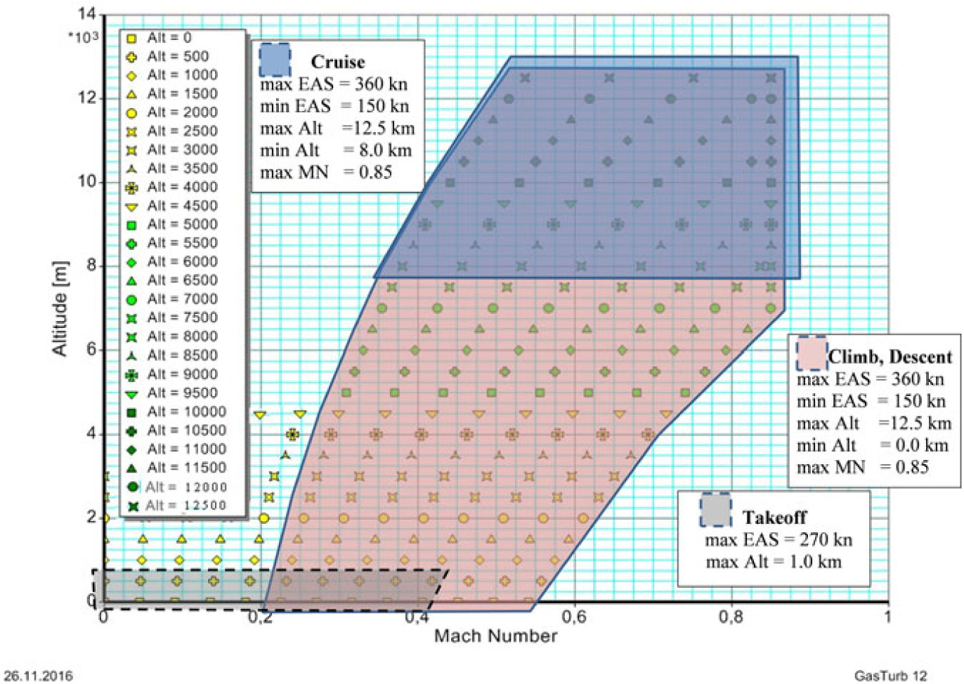
Figure 2. Flight envelope with different flight segments for RJ engine.
For each baseline aircraft, a baseline engine has been selected. They represent a reference for the initial assumptions necessary to build the PS module. Then, baseline engines have been scaled and adapted to match the requirements of the reference aircraft. The baseline engines are listed in Table 2.
Table 2 Baseline engines for RJ and SMRJ reference aircraft

The OBS disciplinary module uses ASTRID (Aircraft on board Systems sizing and TRade-off analysis in Initial Design) tool(Reference Chiesa, Di Meo, Fioriti, Medici and Viola26) developed by Politecnico di Torino. ASTRID is based on empirical and physics-based algorithms, and it can design the main equipment of the major OBS starting from the results of aircraft conceptual design and some specific assumptions. The latter are OBS specific inputs such as the pressure of the hydraulic system, the voltages of the electric system and the pressure of the bleed air. In Fig. 3, the internal design process of ASTRID is described. The design starts with the main utility systems. A different approach is defined for each of them. For example, the Flight Control System (FCS) is designed considering the hinge moment of each of the control surfaces, redundancies and actuator technology. The ECS acquires basic inputs such as number of passengers and flight altitude to calculate the thermal loads and then design the ECS packs. More details about the design process of all OBS can be found in(Reference Chiesa, Di Meo, Fioriti, Medici and Viola26). When the design of the utility systems is completed, the power requirements of each of them is used to design the power distribution and generation systems. Based on the utility systems and the general OBS architecture, the hydraulic and pneumatic systems may not be present (e.g. bleedless configuration). At the end of the process, the global power requirement is computed taking into account the losses in power distribution means and the efficiency of power generation (i.e. the efficiency of the electric generator, hydraulic pump and bleed air system). In addition, simple empirical algorithms are employed to estimate the mass and the volume of each main equipment starting from their main design parameters. For instance, the nominal power of the electric generator or the nominal airflow of the ECS pack.

Figure 3. Internal process of OBS design module (ASTRID tool).
2.2 Application of the AGILE MDAO workflow for PS and OBS matching
For the purpose of the present study, the AGILE MDAO workflow has been used to perform a converged MDA in order to understand the best OBS and PS power matching changing the OBS architecture and evaluating the engine and aircraft performance. In particular, a RJ and a SMRJ aircraft have been studied to understand the different effect of OBS architecture changing aircraft class. With this aim, four different OBS architectures have been defined. Each architecture has a different level of electrification. The electrification level represents the ratio between the total electric energy produced and the other type of energy (i.e. hydraulic and pneumatic) as described in(Reference Fioriti, Boggero, Corpino, Prakasha, Ciampa and Nagel27). Among the several architectures proposed in literature, the ones selected here are in line with the indication provided by Cronin(Reference Cronin6) and a subset of the architectures defined by Chakraborty(Reference Chakraborty and Mavris9). These specific architectures have been selected here because of their similarity with the ones adopted by the newest civil transport aircraft (i.e. Boeing 787 and Airbus A350) and they have been already studied in(Reference Prakasha, Boggero, Fioriti, Aigner, Ciampa, Anisimov, Savelyev, Mirzoyan and Isianov1, Reference Fioriti, Boggero, Corpino, Isyanov, Mirzoyan, Lombardi and D’Ippolito10, Reference Fioriti, Boggero, Corpino, Prakasha, Ciampa and Nagel27) for different purposes. Therefore, the studied architectures could be considered the most promising for future use.
The first OBS architecture depicted in Fig. 4 is the Conventional one with the lowest electrification level. This architecture is adopted by the greater part of the existing aircraft and it represents a reference. For Conventional OBS architecture, the electric, hydraulic and pneumatic power generation and distribution systems are all adopted. Electric and hydraulic systems transform the engine mechanical power by means of, respectively, electric generators and hydraulic pumps. The pneumatic power is provided by the bleed air obtained from some engine compressor stages. A bleed system regulates the pressure and provides the airflow needed by the pneumatic users. In the Conventional configuration, both the ECS and Ice Protection System (IPS) for wing, tail and nacelle leading edges use the compressed air bleeded from the engine. The electric generators supply the avionics, fuel pumps, IPS (for sensors and other small surfaces) and all furnishing elements such as lights, In-Flight Entertainment (IFE), galleys and toilets. The hydraulic pumps provide power for FCS actuators, landing gear actuators and wheel brakes.

Figure 4. Conventional OBS architecture. The systems in bullet points represents the subsystems supplied by respectively electric, hydraulic and pneumatic generation.
The MEA1 architecture is shown in Fig. 5. It represents a first step in OBS electrification and it is in line with the latest Airbus aircraft (i.e. A380, A350), where some FCS lanes are electrical instead of hydraulic(Reference Berlowitz3). Compared to the Conventional one, MEA1 has all the hydraulic users (i.e. FCS, landing gear actuators and wheel brakes) removed and replaced by electric actuators. The Hydraulic Power Generation and Distribution System (HPGDS) is no longer needed, and it is removed in favour of a more powerful electric system. The pneumatic power is still provided by engine compressor stages, as for Conventional OBS. A reduction of OBS total mass is envisaged because of the removal of the HPGDS(Reference van den Bossche28).
Figure 5. MEA1 OBS architecture. The systems in bullet points represents the subsystems supplied by respectively electric, and pneumatic generation.
To further increase the OBS electrification level and avoid the air bleeding from PS, the MEA2 architecture is proposed and depicted in Fig. 6. Here, the pneumatic power has been generated using dedicated centrifugal compressors driven by high voltage electric motors. Given that the IPS for all the leading edges of wing and tail is fully electrified, the ECS is the only pneumatic user for MEA2 configuration. This is in line with the OBS architecture of the Boeing 787(Reference Sinnet11). In MEA2 architecture, the HPGDS is also an electric user that uses the electric driven hydraulic pumps to supply the hydraulic users (i.e. FCS, landing gear actuators and wheel brakes). The electrification of the pneumatic and hydraulic power generations should increase the global efficiency of the OBS systems reducing the power offtakes from the engine.

Figure 6. MEA2 OBS architecture. The systems in bullet points represents the subsystems supplied by respectively electric, hydraulic and pneumatic generation.
Finally, the AEA architecture is included in Fig. 7. It represents the highest level of electrification for OBS, and it is not yet adopted by any civil transport aircraft. The PS is bleedless, and the pneumatic power is provided by dedicated compressors, as in the MEA2 configuration. Moreover, the HPGDS is fully removed using electrical actuators for FCS, landing gear and wheel brakes actuation. This is in line with MEA1 architecture. Therefore, the AEA configuration should add the advantages of mass reduction obtained from MEA1 to the advantages of the greater efficiency reached in MEA2.
Figure 7. AEA OBS architecture. The systems in bullet points represents the subsystems supplied by electric and pneumatic generation.
3.0 OBS AND PS ANALYSES
AGILE MDAO workflow has been employed to analyse the effect of the four OBS architectures applied to different aircraft classes, hence different PS classes. This is useful to understand the rationale behind a positive PS and OBS power matching. The analysis is carried out individuating two reference aircraft corresponding to two different aircraft segments. The first one is a RJ developed within the AGILE research project. This aircraft is in similar to the Embraer E-190, and its main specifications are listed in Table 3. The second reference aircraft is the Airbus A320, which represents the twin engine SMRJ selected as reference. The well-known specifications have been listed to ease the comparison between the two referenced aircraft.
Table 3 Main specifications of reference RJ
Both reference aircraft are equipped with Conventional OBS architecture and with two turbofan engines. The main differences are in terms of absolute power required by OBS, engine dimensions, engine thrust levels, aircraft flight range, number of carried passengers and aircraft mass. From the aircraft design standpoint, the main design drivers are the number of passengers and flight range. In particular, the flight range has a double effect on OBS and PS matching. The first effect is – as well as some other parameters – the increase of aircraft mass. This increases OBS mass, power offtakes and engine thrust. The second effect is the increase in flight time being, in this specific case, equal to the cruise speed of the two referenced aircraft. The increase in flight time gives more importance to more efficient OBS architectures that are able to save more fuel. This point is discussed in more detail in Section 4. In Fig. 8, the mission profiles for RJ and SMRJ are depicted. The main specifications of SMRJ are listed in Table 4.

Figure 8. Mission profile for RJ and SMRJ reference aircraft.
Table 4 Main specifications of SMRJ
3.1 Results of OBS and PS power matching for RJ
The results of the OBS design for RJ are listed in Tables 5 and 6, respectively, in terms of systems’ masses and power offtakes. As previously hypothesized, the increase of the electrification level leads to a reduction of OBS mass. For MEA1, the removal of the HPGDS and the associated mass reduction is not overlooked by the necessary increment of Electric Power Generation and Distribution System (EPGDS) that should produce and distribute more electric power. The MEA1 is the lightest architecture of those considered. Regarding the MEA2 configuration, as can be easily seen in the last line of Table 5, the mass savings obtained by removing the heavy pneumatic pipes and heat exchangers of the bleeding system is almost wasted by the additional mass required by the dedicated compressors and by EPGDS growth. Lastly, the AEA architecture is able to gather the advantages of MEA1 and MEA2. However, the necessary increment of EPGDS mass reduces the total mass savings in comparison with MEA1.
Table 5 Mass breakdown for each OBS architecture for RJ

Table 6 Total power offtakes for each OBS architecture in cruise condition for RJ. All values are per engine

Using the OBS design module, the power required by the systems is also computed for each configuration. In Table 6, the power offtakes from each engine are listed in terms of mechanical power required by the engine gearbox and bleed air airflow taken from engine compressor in cruise condition. They represent the half of the total OBS power required. The difference between Conventional OBS architecture and MEA1 is negligible. This small difference is due to the use of electric actuators instead of the hydraulic ones. However, the FCS is not a power demanding system, and the increase of its efficiency does not lead to a sensible reduction of power offtakes. On the contrary, the difference between Conventional and MEA2 (and AEA) is notable. This is due to the use of bleedless technology. Using this technology, the bleed airflow is totally cancelled but the increase of mechanical power offtake is about 180% compared to Conventional architecture.
It is now clear of the importance of assessing the best PS and OBS matching and including the other disciplinary modules introduced in the MDAO workflow. Firstly, the effect on engine performance should be quantified. In particular, one of the most significant effects is the improvement of the engine performance due to the reduction of bleed air. The change of Specific Fuel Consumption at Max Cruise conditions (SFCMCR) at different bleed airflow rates is depicted in Fig. 9. It is worth noting that a reduction of bleed air, in cruise conditions, from 0.4 kg/s up to 0 improves installed SFCMCR by 3.6%. Using the same engine module, the effect of the mechanical power offtakes is also quantified. The results are shown in Fig. 10, and they reveal that, for instance, an increment of cruise power offtake from 40 to 100 kW increases installed SFCMCR by only 1.7%.
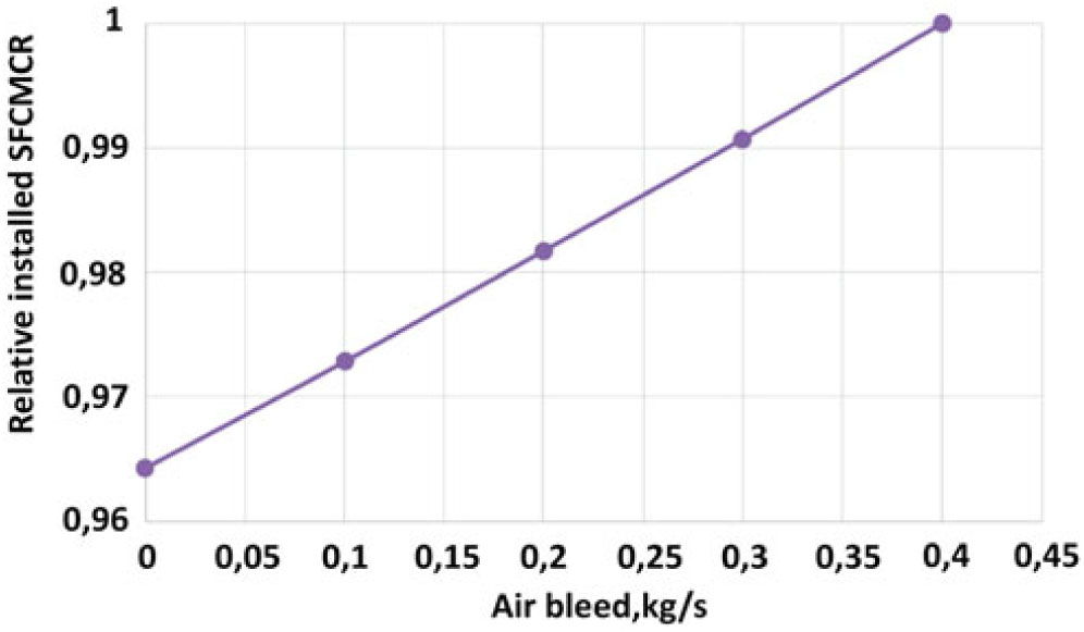
Figure 9. Influence of bleed airflow rate on relative installed SFCMCR.
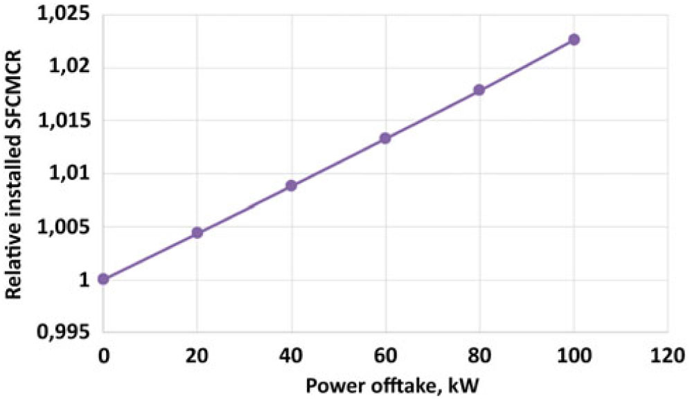
Figure 10. Influence of mechanical power offtakes on relative installed SFCMCR.
Another influence considered in the PS design module is the pressure level of the bleed air required by OBS. In particular, the requirement regarding the minimal value of bleed air pressure in all flight conditions is quite demanding for the engine. The influence of the minimal air bleed pressure on relative value of installed SFCMCR is shown in Fig. 11. It is worth noting that the increase of minimal bleed air pressure from 2 to 6 bars increases the installed SFCMCR by 3%.
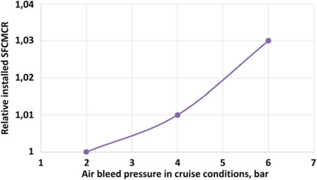
Figure 11. Influence of minimal air bleed pressure on relative installed SFCMCR.
Finally, summing up all the influences on PS performance due to OBS electrification and the different total systems mass, it is possible to recalculate the mission performance of RJ aircraft. With the aim to have more comparable results, the aircraft MTOM and the number of passengers has been kept constant. In this way, it is possible to compare the SFC of the engine for each OBS configuration maintaining the same engine thrust and dimensions. Therefore, a reduction of installed SFCMCR and/or OBS mass produces an increase of the fuel storable in the aircraft, hence a greater mission range.
The results of the analysis are listed in Table 7. It is worth noting that the MEA1 architecture has the main advantage of reducing OBS mass, whereas the influence on installed SFCMCR is negligible. On the contrary, the MEA2 decreases the installed SFCMCR by 2.28%, but the mass experienced a slight reduction. As expected, the AEA significantly reduces both installed SFCMCR and OBS mass extending the aircraft range by 6.63%.
Table 7 Influences of OBS electrification on PS and aircraft mission range compared to Conventional configuration applied to RJ

3.2 Results of OBS and PS power matching for SMRJ
Using the same workflow and focusing on the SMRJ, the OBS masses and power offtakes have been calculated and listed in Tables 8 and 9, respectively Generally, all results are in line with the one obtained for the RJ reference aircraft. However, a remarkable difference can be observed in Table 8 regarding the total systems mass. For the SMRJ, AEA architecture is the lightest one, which is different from the RJ where the MEA1 was the lightest. The main contribution for this result is the relatively lower mass growth of the EPGDS. Considering a bigger aircraft, the electric distribution system (i.e. electric cables and load switching system) is more extended and the use of high voltage significantly reduces its mass(Reference Abdel-Hafez29, Reference Avery, Burrow and Mellor30, Reference Tomasella, Fioriti, Boggero and Corpino31).
Table 8 Mass breakdown for each OBS architecture for SMRJ

Table 9 Total power offtakes for each OBS architecture in cruise condition for SMRJ

As for the RJ, all the influences on PS due to OBS electrification are considered for the study of SMRJ. The results of the study are shown in Table 10. They show an increment of aircraft range as a function of the OBS electrification. This result is due to both the reduced OBS mass and the decrease in installed SFCMCR.
Table 10 Influences of OBS electrification on PS and aircraft mission range compared to Conventional configuration applied to SMRJ

4.0 DISCUSSION OF THE RESULTS
The main aim of this paper is the study of the power matching of PS and OBS changing the OBS electrification level. The study includes two reference aircrafts of different class to understand if different behaviour exists. In Table 11, the influences (in relative terms compared to Conventional architecture) of OBS electrification on PS and aircraft range are compared for both referenced aircraft. Focusing on OBS mass and comparing the results for RJ and SMRJ, the same general trend can be noticed (see Fig. 12). The removal of the HPGDS is the most important factor to reduce the OBS mass. However, the mass of the HPGDS is slightly more important in smaller aircraft than in a bigger one. In the SMRJ, the furnishing and landing gear masses are relatively more significant than the HPGDS mass. This reduces the lightening effect of FCS electrification. Moreover, the opposite happens for ECS electrification that is much more important for SMRJ (-1.92% for SMRJ vs. -0.5% for RJ) because of the ECS size that is directly related to the number of passengers and fuselage length. Considering also the mass savings in the electrical distribution system – more extensive in bigger aircraft – the most electrified architecture (i.e. AEA) is the lightest.
Table 11 Comparison of the influences of OBS electrification for both reference aircraft (relative values compared to Conventional OBS architecture)

Figure 12. Effect of OBS electrification on systems mass.
Regarding the influence of the power offtakes on installed SFCMCR, the trend is generally equivalent between the two referenced aircraft as shown in Fig. 13. However, a greater installed SFCMCR improvement can be seen for SMRJ than for RJ (respectively, -3.45% compared to -2.28%, from Table 11). Electrification of the pneumatic system, i.e. avoiding the use of engine bleed air, increases the efficiency of aircraft carrying more passengers, hence aircraft using more power for ECS in comparison to the other OBS. From Table 12, it is worth noting that, by going from RJ to SMRJ, the bleed air is doubled, while the mechanical power offtake only increases by 50%. This is indicative of the greater importance of the pneumatic system than the other OBS for SMRJ in comparison to RJ.

Figure 13. Influence of OBS electrification on relative PS SFC in cruise conditions.
Table 12 Comparison of power offtakes for RJ and SMRJ

In Fig. 14, the global influence of the electrification on the whole aircraft by means of the variation of mission range is depicted. It confirms the previous results indicating the AEA architecture as the best option for both reference aircraft. Moreover, the results indicate a larger performance improvement for larger aircraft. In particular, for small transport aircraft with reduced range, the OBS mass reduction and bleedless technology give a similar effect on aircraft performance. From Table 11, MEA1 increases mission range by 4.29% and MEA2 by 3.76% for RJ. On the other hand, considering larger aircraft with a more extended range, the increase of engine efficiency due to ECS electrification is more important than the mass contribution. This is confirmed by the results listed in Table 11, where MEA2 increases the mission range by 6.31%, which is more than double of the increment provided by MEA1 (i.e. 2.86%).
Figure 14. Influence of OBS electrification on aircraft range.
5 CONCLUSIONS
With the aim to optimize the power matching of PS and OBS, four different OBS architectures have been selected. Considering the engine power offtakes (quantity and typology) as the first driver for PS and OBS matching, the four architectures have different electrification levels. Their influences on PS efficiency and aircraft range have been analysed by means of several MDA performed using the 3rd generation MDAO workflow developed within the framework of the AGILE research program. Two aircraft belonging to different categories (i.e. RJ and SMRJ) have been selected to understand the different trend in PS and OBS power matching.
The results show a general increment of PS efficiency with increasing OBS level of electrification. In particular, the bleedless architectures are able to reduce by 2 3.5% the engine installed SFCMCR despite the necessary increment in mechanical power offtakes. The bleedless architectures offer greater advantages for SMRJ reference aircraft – compared to RJ – thanks its relatively greater pneumatic power requirement due to the greater number of passengers. Extending the results to the whole aircraft, the effect of the power matching gives additional outcomes. On the one hand, they substantially confirm the previous trend for bleedless architectures. Moreover, the advantage for SMRJ is further increased because of the extended cruise range for this aircraft segment. This is explained by the fact that the fuel savings due to the reduced SFCMCR is proportional to aircraft range. On the other hand, another important result given by this analysis is the relatively lower influence of power offtakes for RJ than SMRJ. Better results have been obtained with lighter OBS architecture (i.e. MEA1) rather than the more efficient one (i.e. MEA2). However, the benefit offered by the two architectures remain comparable; hence, a correct power matching should also be pursued for RJ.
This study has been focused on PS, OBS and their influence on aircraft range. However, the cost and emission estimation should be included to better evaluate the power matching. In particular, the possible savings in fuel cost and emission charges should be balanced with the greater acquisition cost of the electrified OBS. Again, the maintenance cost of these new technologies should be taken into account. The estimation of the influence of engine SFCMCR could also have been refined for bleedless architecture. The PS module could be improved considering engine compressors redesigned to be bleedless instead of using scaled real compressors designed for conventional bleed system.
ACKNOWLEDGEMENTS
The research presented in this paper has been performed in the framework of the AGILE project (Aircraft 3rd Generation MDO for Innovative Collaboration of Heterogeneous Teams of Experts) and has received funding from the European Union Horizon 2020 Programme (H2020-MG-2014-2015) under grant agreement no 636202.


