


Introduction
As the demand for wireless communication is increased in recent times due to existing wireless communication technologies such as UMTS, GPS, WPAN, WiMAX, and WLAN, a need for single multiband antenna with compact size is desired. A fork-shaped antenna is capable of resonating at WiMAX/WLAN band with three radiating elemental stubs and also the antenna shows an omnidirectional radiation pattern [Reference Xu, Xin and He1]. Monopole arms with (Y-shape) asymmetric structure including loaded L-shaped ground plane provides circular polarization for LTE, GNSS, and UMTS-2100 bands [Reference Brar, Saurav, Sarkar and Srivastava2]. A logotype planar antenna with four metal letters (NCNU) is optimized with the help of two optimizers [Reference Weng and Hung3] for multiband applications [Reference Cao, Cheung and Yuk4]. A multiband antenna for GPS, WiMAX, and WLAN wireless applications is reported which consist of rectangular slot, patch with T-shape, T-shaped stub which is inverted, and two stubs with E-shape generate four frequency bands [Reference Chen, Fang, Dong, Han and Liu5]. An insertion of a pair of L-shaped slots, rectangular slots, and defected ground structure provides resonating band for Global Positioning System (GPS), Worldwide Interoperability for Microwave Access (WiMAX), and Wireless Local Area Network (WLAN). An S-shaped strip which is coupled to a U-shaped monopole and meander line coupling with a clip-shaped monopole including inverted-C strip, X-, F-shaped monopole results in a multiband antenna with four frequency bands which is meant for mobile handsets [Reference Cui, Yang, Liu and Li6]. Good impedance match is obtained with Koch Fractal which includes beneath Split Ring Resonator (SRR) which provides multiband characteristics for 1.98, 3.20, 6.30, 8.80, 11.90, 15.70, and 18.30 GHz (L, S, C, X, Ku, K bands) [Reference Elavarasi and Shanmuganantham7]. Introduction of additional resonator inside the slot with a U-shaped resonant patch provides operation at 2.4 and 5.8 GHz, respectively [Reference Leal, Aguilar, Mendez and Herrera8]. Annular ring radiator which is covered with a strip of Rhombus shape and a defected ground plane provides multiband characteristics for WiMAX and WLAN. Defected ground plane is obtained by chamfering and cutting a rectangular-shaped slot [Reference Gautam, Bisht and Kanaujia9]. WLAN operating at 2.4/5.2/5.8 GHz and WiMAX at 2.5/3.5/5.5 GHz are the result of F-shaped slot radiator and defected ground plane [Reference Kumar, Gautam, Kanaujia and Rambabu10]. Microstrip-fed monopole antenna exhibits three resonance modes covering UMTS, WiMAX, and WLAN bands. The rectangular patch includes two symmetric folded slots/step shape microstrip feed line and a rectangular ground plane with dimensions of 30 mm × 34 mm × 0.8 mm [Reference Jalali, Shokouh and Emadian11]. The rectangular patch including two L-shaped stubs and three slots on the ground plane provides circular polarization for WWAN, WiMAX, and WLAN wireless communication systems [Reference Pedram, Nourinia, Ghobadi and Karamirad12]. The antenna with dual polarization, one circularly polarized (CP) for IEEE802.11 b/g bands and other linearly polarized for IEEE802.11 a/n/ac/ax bands, is reported which is obtained by asymmetric U-shaped slot in the ground plane [Reference Saxena, Kanaujia, Dwari, Kumar and Tiwari13]. A dual-band antenna with integrated amateur band and ultra wideband which also includes notched band characteristics is reported. The antenna is also analyzed in terms of its equivalent circuit model with resonant circuits. Also, amateur band operates with 1.2 GHz band and UWB band from 3.2 to 13.9 GHz [Reference Srivastava, Kumar, Kanaujia and Dwari14]. A flower-shaped planar monopole antenna is capable of working in three different bands operating at 1.576 GHz for GPS, 2.668 and 3.636 GHz for mobile WiMAX [Reference Ullah, Faisal, Ahmad, Ali, Tahir and Flint15] which is designed on FR4 substrate with a dielectric constant 4.3. A textile-based body worn antenna is reported [Reference Wang, Lee, Psychoudakis and Volakis16] for Global System (Mobile communication/Personal Communication Services/Wireless Local Area Network) bands which is fabricated using densely embroidered metal-coated polymer fibers. Analyzation is carried out for three U-shaped slot-loaded rectangular patches with defected ground plane for 9.75, 11.55, 12.15, 13.49, and 14.30 GHz [Reference Nagendra17].
In this manuscript, a monopole antenna with a rectangular ground plane is presented which is capable of operating for different wireless communication systems such as WWAN, Bluetooth, WiMAX, WLAN, and Downlink satellite system. The antenna is fabricated on RT Duroid/5880 substrate with compact dimensions of 20 mm × 20 mm × 0.787 mm and exhibits an omnidirectional pattern.
Antenna design
Figure 1 represents the multiband antenna which is designed and fabricated on Rogers RTDuroid5880 substrate with permittivity ε r = 2.2, tanδ = 0.0009. Figure 1(a) shows a tilted view of the proposed multiband antenna with a compact dimension of W mm × L mm × h mm. The radiating patch is fed by microstrip which is connected to 50 Ω SMA connector on one face of the substrate and the other side is printed with the ground plane. Figure 1(b) shows the radiating patch which is connected to four-quarter wavelength stubs intended to resonate at 1.9, 2.4, 3.5, and 5.5 GHz. The radiating patch is also etched by an inverted C-shaped slot which is responsible for a resonant frequency of 7.5 GHz intended for Downlink satellite system. The ground plane consists of two rectangular stubs and chamfered ground edges for better impedance matching of the final version of the multiband antenna. All the parameters are optimized by HFSS simulator and are given below in Table 1.
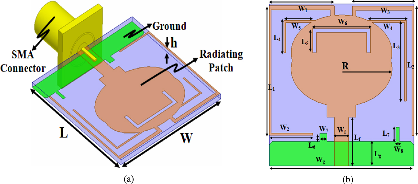
Fig. 1. (a) Tilted view of the proposed circularly polarized multiband antenna. (b) Front view.
Table 1. Optimized parameters of the proposed antenna

Figure 2 shows the design steps of the proposed antenna working in a single band. Figure 2(a) represents the radiating antenna with a single ellipse of radius R = 7.00 mm and an eccentricity ratio of 0.67. VSWR shows Antenna 1 resonating at 8.25 GHz with a bandwidth covering 7.17–9.59 GHz represented in Fig. 2(c). In order to improve the resonating frequency, an ellipse of radius R with an eccentricity ratio of 0.67 is embedded on antenna 1 as shown in Fig. 2(b) with a new resonating frequency centered at 4.11 GHz and covering a bandwidth of 3.16–5.25 GHz.

Fig. 2. (a) Step 1. (b) Step 2. (c) VSWR.
Figure 3 shows the antenna configuration which is developed to obtain five bands of operation and also illustrates the respective VSWR. Antenna 1 depicts a basic monopole antenna resonating at 4.10 GHz with a return loss of −25.96 and a covering bandwidth of 3.16–5.25 GHz. To obtain the first band of operation working in WWAN as shown in Fig. 3(b), a quarter wavelength stub is attached which resonates at 1.91 GHz covering a bandwidth of 1.73–2.02 GHz with a corresponding return loss of −18.29. The stub length is calculated by L WWAN = W 1 + L 1 + W 2. Furthermore, to obtain a dual band of operation, Antenna 2 is modified to Antenna 3 represented by Fig. 3(c) which is obtained by adding a quarter wavelength corresponding to the application for Bluetooth which is calculated by L Bluetooth = W 3 + L 2. Antenna 4, shown in Fig. 3(d), corresponds to tri band of operation which includes WWAN, Bluetooth, and WiMAX band and a corresponding quarter wavelength stub is calculated by L WiMAX = W 4 + L 3. Figure 3(e) represents the conversion of Antenna 4 to Antenna 5 with an additional band working in WLAN which is obtained by embedding the quarter wavelength stub given by L WLAN = W 5 + L 4.

Fig. 3. (a) Antenna 1. (b) Antenna 2. (c) Antenna 3. (d) Antenna 4. (e) Antenna 5. (f) Antenna 6. (g) Antenna 7. (h) VSWR.
A final version of the proposed antenna is shown in Fig. 3(f). Downlink satellite system band is obtained by inserting a C-shaped slot on Antenna 6 which resonates at 7.4 GHz with a return loss of −13.57 and a corresponding slot length is calculated by L Downlink Satellite = W 6 + 2L 5. Antenna 7 shown in Fig. 3(g) is the improved version of Antenna 6 which is obtained by chamfering the edges of the ground plane and inserting two stubs of dimensions W 7 × L 6 mm2 and W 8 × L 7 mm2. Design steps with bandwidth coverage and respective return loss are tabulated in Table 2 which is given below.
Table 2. Antenna configuration with respect to bandwidth and return loss (Antenna 2 to Antenna 7)

Optimization of key parameters, surface current density
Distribution and axial ratio
Optimization of key parameters leading to change in performance characteristics affecting various parameters such as matching of input impedance is carried out by EM simulator (Full Wave Ansyss HFSS simulator). Shifting of resonating bands either on lower or higher frequency side is due to a variation of the physical length of the stubs and slots which in turn also affects the bandwidth. The said analysis is discussed below:
Figure 4 represents the optimization of key parameters for the proposed five-band antenna and analysis of axial ratio (AR). Figure 4(a) depicts the optimization of W 2 for WWAN wireless application. Variation of W 2 from 5.50 to 6.50 mm suggests shifting of resonance frequency from 2.15 GHz (return loss = −57.26) to 1.44 GHz (return loss = −32.57). However, for W 2 = 6.00 mm, required bandwidth (1.67–2.01 GHz) is obtained with a maximum return loss of −48.36 at a resonance frequency of 1.90 GHz. Optimization for Bluetooth application band is shown in Fig. 4(b) which confirms that a variation of L 2 from 15.5 to 16.5 mm leads to shifting of resonance frequency from 2.85 GHz (return loss = −38.02) to 2.40 GHz (return loss = −32.11). By fixing L 2 = 16.00 mm, required bandwidth for Bluetooth (2.39–2.67 GHz) application is obtained with resonance frequency centered at 2.51 GHz (return loss = −36.98). Figure 4(c) shows the variation of L 3 from 9.50 to 10.50 mm with resonance frequency also varying from 3.75 GHz (return loss = −32.15) to 3.28 GHz (return loss = −17.82), respectively. The optimized value for L 3 corresponds to 10.00 mm with bandwidth (3.26–3.75 GHz) centered at 3.51 GHz including return loss (−23.03). Figure 4(d) represents the optimization for WLAN which corresponds to the stub length L 4. Variation of L4 from 3.50 to 4.50 mm leads to shifting of resonance frequency from 6.10 GHz (return loss = −55.11) to 5.28 GHz (return loss = −26.03) and the optimized value for L 4 = 4.00 mm achieves WLAN band (4.95–5.86 GHz) with resonance frequency centered at 5.54 GHz (return loss = −39.59). Figure 4(e) shows the optimization graph for Downlink Satellite system. Variation of L 5 from 2.50 to 3.50 mm achieves shifting of resonant frequency from 6.95 to 7.80 GHz. For L 5 = 3.00 mm, a necessary bandwidth (6.97–7.67 GHz) is obtained with a return loss equal to −25.98 corresponding to 7.35 GHz resonance frequency.

Fig. 4. Optimization of parameter (a) W2 (WWAN), (b) L2 (Bluetooth), (c) L3 (WiMAX), (d) L4 (WLAN), (e) L5 (Downlink Satellite), (f) axial ratio.
A patch antenna can produce a circular polarization so long as two perpendicular modes are excited simultaneously with the same amplitudes and 90°' phase difference. In order to show the functionality of an antenna in circular polarization, the parameter of 3 dB AR is used. The AR of the proposed antenna is shown in Fig. 4(f). The 3 dB bandwidth of the proposed antenna is in 1.93 GHz positioned between 1.70 and 1.97 GHz. Linear polarized antenna working in different bands which can radiate equally around it in the horizontal plane and also enables a large proportion of their power radiated near the surface of the earth. This type of polarization finds its applications with the use of automobiles. Whereas, a handheld transmitter which finds movement around a room/warehouse where antenna often oriented in different degrees off axis, it becomes necessary for the fixed antenna to radiate hemispherical-shaped pattern and hence circular polarization plays a vital role with advantages such as combating the effect of multipath interference or fading of received signals. The use of CP antenna is advantageous as it can launch and receive CP electromagnetic waves and is relatively less sensitive to their respective orientations. The CP monopole antenna can be widely used in many aspects such as radar, navigation, electronic countermeasure system, and medical application. WWAN bands is intended to cover applications such as Digital Cellular System (1.71–1.88 GHz), Personal Communication System (1.85–1.99 GHz), and Universal Mobile Telecommunication system2100 (1920–2170 MHz) which needs to receive signals in all the directions and hence the antenna needs to be CP. The proposed antenna is CP for above said applications as AR is near to 1 dB. For remaining applications, including Bluetooth, WiMAX, WLAN, and X-Band Downlink system, the proposed antenna fulfills the requirement of linear polarization.
Antenna analysis can be further characterized by studying the surface current density distribution which is shown in Fig. 5. Multiband performance is defined in terms of current distributions of the proposed multiband antenna at the frequencies of 1.92, 2.41, 3.54, 5.55, and 7.50 GHz as shown in Figs 5(a) and 5(e), respectively. The current surfaces around the stubs at the frequencies of 1.92 and 2.41 GHz are more vivid. The current distributions of the proposed antenna at the frequencies of 3.54, 5.55, and 7.50 GHz are simulated and shown in Figs 5(c) and 5(e). As can be clearly seen, the antenna radiation is affected more at the abovementioned frequencies and the surface currents are more visible in the vicinity of both slots and stubs, and accordingly, the effects mentioned above show that the proposed antenna operates in multi bands.

Fig. 5. Surface current distribution at (a) 1.92 GHz, (b) 2.41 GHz, (c) 3.54 GHz, (d) 5.55 GHz, (e) 7.50 GHz.
Results and discussion
Figure 6(a) shows the comparison simulated result with measures and Fig. 6(b) shows the fabricated prototype. Impedance mismatch between the feedline and its relative impedance (SMA connector) leads to dissipation of power which is characterized in terms of return loss which is positive which means more and positive [Reference Trevor18] leads to better impedance matching. A prototype is developed and fabricated on Rogers RTDuroid5880 substrate. This leads to simulated and fabricated results and are compared as shown in Fig. 6(a).

Fig. 6. (a) Return loss comparison. (b) Fabricated prototype. (c) Peak gain (dBi).
Excited proposed antenna shows multi-resonance characteristics resonating at 1.93, 2.51, 3.47, 5.52, and 7.43 GHz resulting five bands of operation. Lower frequency band resonating at 1.93 GHz covers the bandwidth of 1.67–2.13 GHz which also exhibits circular polarization. Also antenna resonating at 2.51, 3.47, 5.52, and 7.43 GHz covers the measured bandwidth of 2.36–2.70, 3.20–3.90, 5.10–6.00, and 0.10–7.90 GHz. Dissimilarity between simulated and measured results may be an error in the fabrication and soldering processes.
Figure 6(c) shows the peak gain comparison of simulated and measured results which are obtained for resonating frequencies of the proposed antenna 1.88, 2.55, 3.49, 5.55, and 7.51 GHz which corresponds to the peak gain of 7.22, 5.11, 3.30, 5.02, and 6.02 dBi. Gain at 1.88 GHz is high compared to other resonating frequencies as the addition of two stubs in the ground plane improves impedance matching resulting in higher gain at lowest resonating band.
Radiation patterns are used to signify how field power of an antenna is radiated from a fixed direction. Radiation pattern in E- and H-planes with co- and cross-polarization is shown in Fig. 7 with an operating frequency of 1.92, 2.41, 3.54, 5.55, and 7.50 GHz. It can be observed that the radiation pattern of the proposed antenna has less cross-polarization interference with respect to resonating frequencies in the operating band. The proposed antenna offers less cross-polarization interference which is due to thickness (h = 0.787 mm) and dielectric constant (ε r = 2.2) of microwave substrate. Also, the reduced size of the ground plane (W g × L g = 20 × 3 mm2) ensures the less cross-polarization interference.

Fig. 7. Measured radiation pattern of E- and H-planes in dB at (a) 1.92 GHz, (b) 2.41 GHz, (c) 3.54 GHz, (d) 5.55 GHz, (d) 7.50 GHz.
Table 3 shows the comparison of earlier published work with the proposed work. As compared with reference [Reference Pedram, Nourinia, Ghobadi and Karamirad12] which covers five bands of operation, the proposed antenna size is reduced by 12% and also the gain of the proposed antenna is 7.22 dBi. All the above discussed advantages of the proposed antenna make it more suitable for different wireless applications.
Table 3. Comparison of the proposed antenna parameters with several existing antennas

* P – Proposed Antenna.
Bold signifies Maximum Gain, Number of Separated Bands, Size, Bands of proposed antenna so as to distinguish from other published works. *Signifies Proposed work.
Conclusion
A prototype compact multiband antenna resonating at 1.92, 2.41, 3.54, 5.55, and 7.50 GHz is presented. Five bands of operation are obtained by adding four stubs and an inverted C-shape slot. Due to the compact size and simple structure, the proposed antenna is easily fabricated. Standard wireless communication bands include DCS, PCS, Bluetooth, WiMAX, WLAN, and Downlink satellite system. The antenna is CP for WWAN for AR 3 db bandwidth. Good impedance bandwidth, high gain, and good radiation pattern in the application bands justify the simulated and measured results which make it quiet suitable for multiple wireless applications.
Author ORCIDs
Manish Sharma, 0000-0002-1539-2938
Acknowledgement
The author is thankful to the Advance Microwave Antenna Testing Laboratory (URL: delhi.gov.in/wps/wcm/connect/doit_gbpec/GBPEC/Home/List+of+Labs), G. B. Pant Engineering College, Delhi for providing Antenna Measurement Facility.
 Manish Sharma received the B.E. degree in Electronics and Communication Engineering from Mangalore University, Karnataka, India in 2000 and the M. Tech degree from Visvesvaraya Technological University, Karnataka, India in 2007. He is currently working toward the Ph.D. degree at the Department of Electronics Engineering, Banasthali University, Rajasthan, India. He is currently working as an Associate Professor in Electronics and Communication Engineering, Aravali College of Engineering & Management, Faridabad, India. His research interest includes UWB antennas, RFID antennas, Planar Microwave filters, Phase Shifter, and Planar antenna on Si Substrate.


