NOMENCLATURE
- D
diameter of jet hole (mm)
- H
length of jet hole (mm)
- L
total length of impingement chamber (mm)
- A
semi-major axis of the cross section of the chamber (mm)
- B
semi-minor axis of the cross section (mm)
- L 1
length of first straight section (mm)
- C
length of transition section, length of semi-elliptical arc (mm)
- VR
-
cross-flow velocity ratio
- V c
-
mean velocity of cross flow (m/s)
- V i
-
mean velocity of jetting flow (m/s)
- Nu
-
Nusselt number
- h
-
heat transfer coefficient (W/K/m2)
- q
-
wall heat flux (W/m2)
- T
-
temperature (K)
- TR
-
cross flow temperature ratio
Subscripts
- c
-
cross flow
- i
-
impingement
- h
-
hydraulic
- w
-
wall
1.0 INTRODUCTION
To achieve higher gas turbine power output and efficiency, the turbine inlet temperature applied has been increasing continuously. The inlet temperature of gas turbine vanes is now much higher than the melting temperature of gas turbine materials, which requires innovative and effective cooling technology to protect the vanes from damage(Reference Han, Dutta and Ekkad1). In general, gas turbine cooling technology can be divided into two categories, namely external cooling technology and internal cooling technology. External cooling is often referred to as film cooling, while internal cooling includes techniques such as rib-roughed cooling, swirl cooling and impingement cooling. Impingement cooling can directly impact onto a target wall and destroy the boundary layer, thus enhancing the heat transfer greatly. At present, impingement cooling is widely applied for gas turbine cooling. In particular, the leading edge of the vane bears the direct impact of high-temperature gas, and the heat transfer coefficient is rather high. As a result, impingement cooling is normally adopted in the gas turbine vane leading edge.
However, the spent air from the upstream jets will form a cross flow, which will deflect the downstream jets and weaken the heat transfer. Therefore, much attention has been paid to the effects of cross flow on impingement cooling. Metger and Korstad(Reference Metzger and Korstad2) first studied the effect of cross flow on array impingement cooling and found that the cross flow would weaken the heat transfer of a target surface. Behbahani and Goldstein(Reference Goldstein and Behbahani3) also studied this problem and reached similar conclusions. To suppress cross flow and enhance the heat transfer of impingement cooling, many studies have been conducted. Taslim(Reference Taslim and Bethka4) arranged straight ribs on a target surface to enhance the impingement heat transfer. However, the ribs do not affect the jet impingement itself. Chi(Reference Chi, Kan, Ren and Jiang5) proposed a kind of anti-cross-flow structure that increases the section areas for cross flow. Wang(Reference Wang, Wang and Sunden6–Reference Wang, Luo, Wang and Sunden9) arranged a triangle vortex generator pair in the impingement chamber, and suppressed the cross flow, but this kind of vortex generator pair would result in difficulties for the manufacture of impingement chambers.
A study on the alternating elliptical channel(Reference Meng, Liang, Li and Guo10) showed that this kind of channel can generate a pair of longitudinal vortices while leaving the channel section areas unchanged. In addition, the longitudinal vortex generated by an alternating elliptical channel can further enhance the heat transfer. To reveal the mechanism of heat transfer enhancement in alternating elliptical channels, a series of studies have been conducted. Meng et al.(Reference Meng, Liang, Chen and Li11) investigated the heat transfer of an alternating elliptical tube experimentally for a range of Reynolds numbers of 500 < Re < 5 × 10⁴. They found that the heat transfer was greatly enhanced, while the total pressure loss increased less than that of the ribs. Chen et al.(Reference Chen, Guo and Chen12) investigated the flow and heat transfer characteristics in an alternating elliptical tube using a low-Reynolds-number turbulence model numerically. They concluded that the transition sections of the alternating elliptical tube have the greatest effect on the enhancement of the heat transfer, but that these sections also cause an increase in pressure drop. Li et al.(Reference Li, Feng, He and Tao13) conducted an investigation on the flow and heat transfer characteristics in an alternating elliptical tube experimentally and numerically, and found that the laminar flow transitioned to the turbulent flow when the Reynolds number reached 1,000. The numerical results revealed that the multi-longitudinal vortex was emanated from the secondary flow and clearly improved the synergy between the velocity and temperature gradient field. Furthermore, the alternating elliptical tubes reduced the pumping power to achieve the same heat transfer enhancement effect.
Recently, more attention has been paid to the effect of geometrical parameters and working fluid type on heat and flow characteristics. Sajadi et al.(Reference Sajadi, Yamani, Ashtiani and Kowsari14) investigated the heat transfer and total pressure loss of oil flow in alternating elliptical tubes, flattened tubes and circular tubes experimentally and numerically. The numerical results indicated that the heat transfer increased with a decrease of the aspect ratio and pitch length. In addition, alternating elliptical tubes performed much better than flattened or circular tubes. Hasan et al.(Reference Hasan and Hamid15) conducted a numerical study on the turbulent flow and the heat transfer characteristics of liquid water flow in the alternating elliptical tube when the alternating angles vary. They aimed to enhance the heat transfer by generating multi-longitudinal vortices along the tube. When the alternating angle between two pitches increases, the number of the multi-longitudinal vortices can increase from two to four, and then eight. This increase of the number of the multi-longitudinal vortices accelerates the cold fluid in the centre of the tube to increase interaction and mixing with the hot fluid close to the wall. Khaboshan et al.(Reference Khaboshan and Nazif16) performed a numerical simulation to study the entropy generation and the turbulence of flow in an alternating elliptical tube under different alternating angles between two pitches with a constant wall temperature boundary condition. The turbulent flow of the liquid water fluid was simulated at Reynolds numbers ranging from 10,000 to 60,000. The numerical results showed that the multi-longitudinal vortices have the main effect on the heat transfer enhancement, total pressure drop and entropy generation. Two or four symmetrical vortices with the same direction of rotation near the tube wall promote local fluid mixing and wall shear stress, and the local total entropy generation of the tube decreases.
A series of studies have been conducted on the alternating elliptical channel, revealing that this kind of channel can generate multi-longitudinal vortices(Reference Xiao, Wang and Feng17,Reference Xiao, He and Feng18) . On this basis, to suppress the cross flow and enhance the heat transfer in the gas turbine leading edge, a kind of alternating elliptical impingement chamber is proposed herein. Numerical simulations were performed by using a 3D steady solver of the RANS equations with the SST k–
 $\omega$
turbulence model. To reveal the mechanism of cross-flow suppression and heat transfer enhancement, the simulation results are compared with those for a smooth semi-elliptical impingement chamber.
$\omega$
turbulence model. To reveal the mechanism of cross-flow suppression and heat transfer enhancement, the simulation results are compared with those for a smooth semi-elliptical impingement chamber.
2.0 PHYSICAL MODEL AND NUMERICAL METHOD
2.1 Physical model
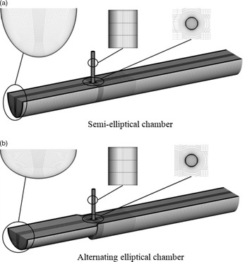
To investigate the influence of the alternating elliptical chamber on the cross-flow suppression and heat transfer enhancement of impingement cooling, two kinds of impingement chambers are studied in this paper, as shown in Fig. 1. Figure 1(a) shows the smooth semi-elliptical impingement chamber, and Fig. 1(b) shows the alternating elliptical chamber. For the semi-elliptical impingement chamber, the cross section of the chamber remains uniform as a semi-ellipse. The cross flow enters the chamber from the direction of the negative X-axis, while the impingement jet enters from the direction of the Z-axis. The semi-major axis of the cross section of the chamber is parallel to the jet direction, so that the impingement distance is equal to the length of the semi-major axis. For the alternating elliptical chamber, there are two straight sections and one transition section. In the first straight section, the cross section of the chamber is a semi-ellipse, and its minor semi-axis is parallel to the jet direction. During the alternating process in the transition section, the major axis gradually changed into the minor axis, and the minor axis gradually changed into the major axis at the same time. It is worth pointing out that the cross-section areas of the chamber remain constant during the alternating process.
Figure 1. The geometries of the two physical models.
Three views and the dimensions of these two kinds of impingement chambers are shown in Fig. 2. The diameters of the jet holes for the two kinds of impingement chambers, D, are all equal to 2.5mm, and the lengths of the jet holes, H, are equal to four times D, namely 10mm. For these two kinds of impingement chambers, the total lengths, L, are all equal to 62 times of D. The semi-major axis of the cross section of the chamber, A, is equal to 5.2 times D, and the semi-minor axis of the cross section, B, is equal to four times D; thus, the aspect ratio is 1.3. For the alternating elliptical chamber, the length of the first straight section, L 1, is equal to 20 times D, and the length of the transition section, C, is equal to the diameter of jet holes. The jet holes are located at multiples of D downstream of the transition outlet, and the second straight section of the alternating elliptical chamber measures 40D. It should be noted that the jet holes are located at the same positions for both kinds of impingement chambers for comparison purposes.
Figure 2. Three views and dimensions of the geometries.
2.2 Data reduction
The cross-flow velocity ratio VR is defined as
 \begin{equation}VR = \frac{{{V_{\rm{c}}}}}{{{V_{\rm{i}}}}},\end{equation}
where V c and V i are the mean velocity of cross flow and jetting flow, respectively.
The cross-flow velocity ratio gives an indication of the strength of cross flow. Generally, with an increase of upstream impingement jets, the velocity of the cross flow increases, as does the cross-flow velocity ratio. At the same time, with an increase of velocity ratio, the deflection effect of the cross flow on the impingement jets is more obvious. In the present paper, the effects of the velocity ratio on the impingement jets are studied for these two kinds of impingement chamber, namely the semi-elliptical chamber and alternating elliptical chamber. For the primary simulation and comparison, the cross-flow velocity ratio is maintained at 0.2. Then, the cross-flow ratio range of 0.1–0.5 is studied.
The cross-flow temperature ratio TR is defined as Equation (2):
 \begin{equation}TR = \frac{{{T_{\rm{c}}}}}{{{T_{\rm{i}}}}},\end{equation}
where, T c and T i are the temperature of cross flow and jetting flow, respectively. For the primary simulation, this temperature ratio is set to 1. Then, the temperature ratio range of 1.05–1.2 is studied.
The local Nusselt number is defined as Equation (3):
 \begin{equation}Nu=\frac{hD_{{\rm h}} }{\lambda } =\frac{q}{T_{{\rm w}} -T_{{\rm i}} } \bullet \frac{D_{{\rm h}} }{\lambda }\end{equation}
where h is the heat transfer coefficient, D
h is the hydrodynamic diameter, q is the wall heat flux, T
w is the wall temperature of target surface, T
i is the temperature of jetting and
 $\lambda$
is the thermal conductivity of the air near the wall.
$\lambda$
is the thermal conductivity of the air near the wall.
The local Nusselt number represents the intensity of heat transfer. To evaluate the span-wise averaged heat transfer, the span-wise averaged Nusselt number is defined as Equation (4):
 \begin{equation}N{u_{{\rm{ave,sp}}}} = \frac{{\int_{\rm{C}} {Nuds} }}{C},\end{equation}
where C is the length of the semi-elliptical arc and Nu is the local Nusselt number.
2.3 Boundary conditions
In this study, the flow is set as compressible by using ideal air gas as the working fluid. The operating conditions for two kinds of impingement chambers are set the same to allow fair comparison of results. Specifically, the static inlet temperature of jetting is maintained at 350K, and the velocity is 50m/s. The temperature for cross flow is set as 350K, and the velocity is dependent on the cross-flow ratio. For the primary calculation, the cross-flow ratio is set as 0.2, so that the velocity of cross flow is 10m/s. The target surface temperature is kept constant at 500K. Thus, the temperature ratio between the coolant and target surface is 0.7, similar to the operating temperature ratio in real applications of impingement cooling. Non-slip walls are specified for all walls. Except for the target surface, all the other walls are set as adiabatic. At the outlet, a static pressure of the atmospheric pressure, namely 101.325kPa, is applied.
Cases in this study are all steady-state solutions and simulated by the commercial software ANSYS CFX 19.0. All iterations were continued until the residuals for all equations reached stability to ensure steady-state conditions. The root-mean-square (RMS) normalized scaled values of the equation residuals were less than 10−5 for all three components of velocity, energy, turbulent kinetic energy, dissipation rate and continuity equation.
Figure 3. Mesh of the models for calculation.
2.4 Meshing procedure
For the calculation domain in this study, a high-quality structured mesh was obtained by using the commercial code ICEM CFD 19.0, as shown in Fig. 3. The main body is discretized by an H-type grid. To get a higher-quality mesh, C-type grids are applied to discretize the shroud and hub, and O-type grids are adopted for the jet nozzle. The mesh refinement for the jet nozzle is set as the same around the jet nozzle. Boundary layers are applied to all wall surfaces, by densely refining near-wall region mesh. The dimensionless wall distance value (y+) of the first layer is less than 1.0, and the stretch ratio of the boundary-layer development is 1.1. The calculation results with four different meshes with different grid numbers of 0.5, 1, 1.5 and 2m revealed that meshes with a grid number of 1.5m can ensure the requirement of grid independence. For the final meshes, the 3 × 3 × 3 qualities are all above 0.8.
2.5 Validation of turbulence models
Turbulence model validation was performed with four kinds of turbulence models, namely standard k–
 $\varepsilon$
, Renormalisation Group (RNG) k–
$\varepsilon$
, Renormalisation Group (RNG) k–
 $\varepsilon$
, k–
$\varepsilon$
, k–
 $\omega$
and SST k–
$\omega$
and SST k–
 $\omega$
. In the turbulence model validation, for all numerical simulations, the boundary conditions are the same as in the experiment in Ref. (Reference Xing, Spring and Weigand19). The circumferential averaged Nusselt number calculated by four kinds of turbulence models is compared with the result of the experiment. Figure 4 shows the calculation results for the turbulence validation. The prediction results of the SST k–
$\omega$
. In the turbulence model validation, for all numerical simulations, the boundary conditions are the same as in the experiment in Ref. (Reference Xing, Spring and Weigand19). The circumferential averaged Nusselt number calculated by four kinds of turbulence models is compared with the result of the experiment. Figure 4 shows the calculation results for the turbulence validation. The prediction results of the SST k–
 $\omega$
turbulence model for impingement cooling are in best agreement with the experimental results, while the standard k–
$\omega$
turbulence model for impingement cooling are in best agreement with the experimental results, while the standard k–
 $\varepsilon$
turbulence model and standard k–
$\varepsilon$
turbulence model and standard k–
 $\omega$
turbulence model over-predict the heat transfer, and the prediction results of the RNG k–
$\omega$
turbulence model over-predict the heat transfer, and the prediction results of the RNG k–
 $\varepsilon$
turbulence model are obviously lower than the experimental results. Thus, the SST k–
$\varepsilon$
turbulence model are obviously lower than the experimental results. Thus, the SST k–
 $\omega$
turbulence model was adopted for all the calculations in this study.
$\omega$
turbulence model was adopted for all the calculations in this study.
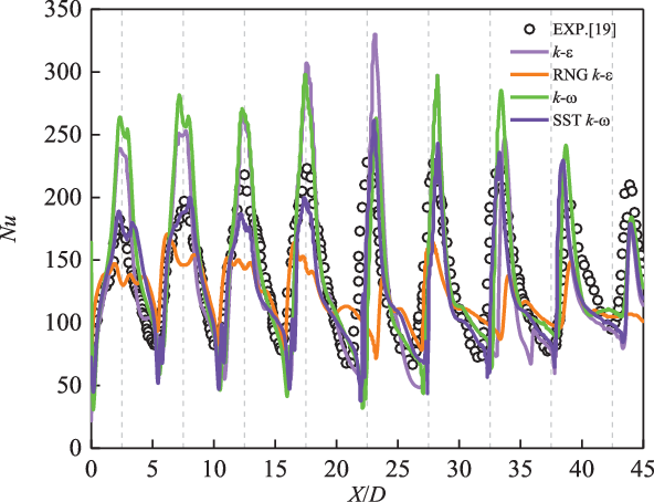
Figure 4. Results of turbulence model validation.
3.0 RESULTS AND DISCUSSION
3.1 Flow field
For all cases, velocity contours and streamlines of three planes perpendicular to the main flow are presented. Figure 5 shows the streamlines and contours of the velocity in Z direction on three vertical sections of the impingement chamber (X/D = −2, X/D = −1 and X/D = 0). Among them, section X/D = 0 is the cross section at the centre of the jet hole, while sections X/D = −2 and X/D = −1 are located 2D and 1D upstream of the jet hole centre. The left column is the velocity contour and streamlines of the semi-elliptical chamber, and the right one is the alternating elliptical chamber.
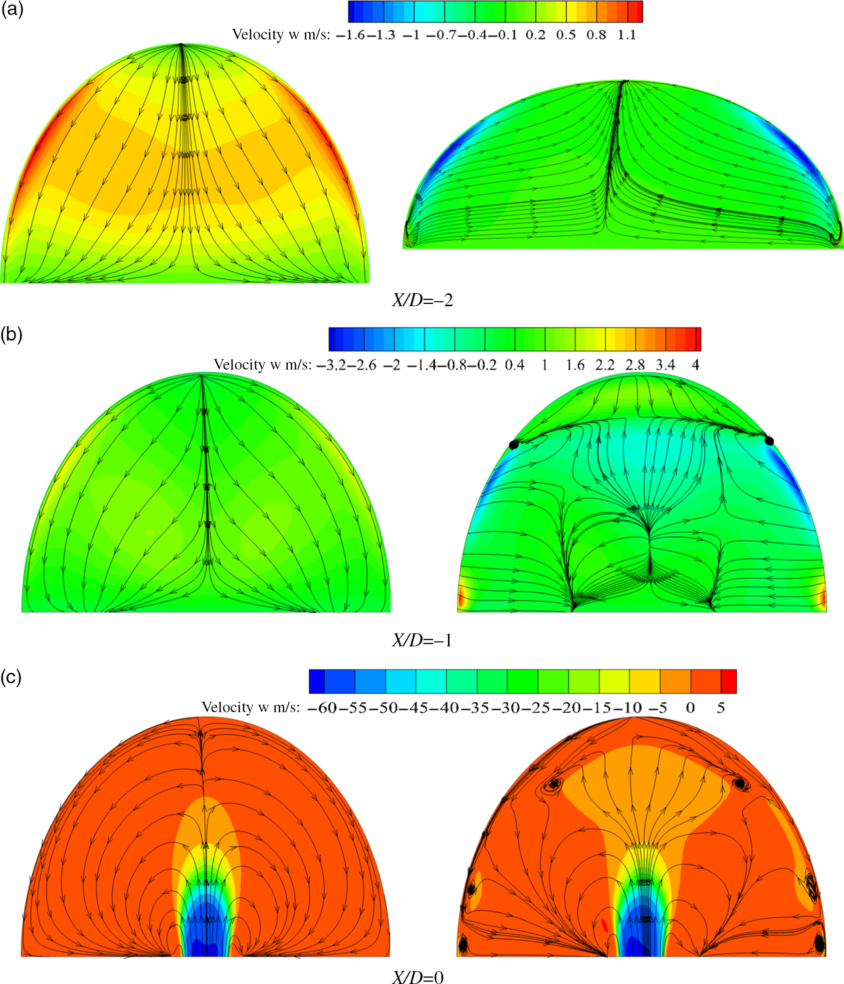
Figure 5. Streamlines and contours of the velocity in Z direction.
It is obvious that the flow and velocity distributions in the two kinds of impingement chamber are completely different. For the semi-elliptical chamber, on the plane X/D = −2, influenced by the reserve flow of jet impinging onto the target surface, the velocity in Z direction on the whole cross section is along the direction of positive Z axis. In other words, the flow is contrary to the direction of the impingement jet. For velocity distribution, the velocity in the middle of the chamber is larger than the velocity at the top and bottom. In the X/D = −1 section, for the semi-elliptical impingement chamber, the flow velocity on the section opposite to the direction of the impingement jet increases. At the same time, the streamlines are more concentrated to the centre. Section X/D = 0 is located at the centre of the jet hole. The impingement jet sprays from the hole and impacts on the target. However, influenced by the cross flow, only fluid in the centreline can reach the target surface. The other jet flow is taken away by the cross flow to form a pair of vortices.
For the alternating elliptical chamber, the X/D = −2 section is located at the transition section. It can be seen that, due to the alternating of the cross section, a pair of longitudinal vortices is generated that has the same flow direction as the jet flow on the centreline. This pair of longitudinal vortices is beneficial to increase the momentum of the impinging jet and enhance the jet penetration ability. In section X/D = −1, the cross flow, longitudinal vortex pair and reserve flow of the impingement jet interact with each other, making the vortex structures rather complex. Even though the flow velocity of the centreline in the middle section is still upward overall, the reverse flow of the impingement jet is suppressed. From section X/D = 0, the difference in the flow field between the two kinds of impingement chamber can be observed more clearly. The penetration depth of the alternating elliptical chamber is larger than that of the semi-elliptical chamber, and in most regions the flow velocity is upward. Moreover, it should be pointed out that four smaller longitudinal vortices are generated near the wall, which would further enhance the heat transfer in areas that the impingement jet cannot cover.
To further reveal the mechanism of cross-flow suppression in an alternating elliptical chamber, Fig. 6 shows the Z velocity distribution on the section vertical to the jet at the position near the target surface (Z/D = −4). It can be seen from this figure that, in contrast to the results for the semi-elliptic cylinder impingement chamber, the Z velocity on the near-wall section of the alternating elliptical impingement chamber increases and the area of the jet high-speed zone expands. On the other hand, the alternating elliptical impingement chamber restrains the cross flow, and the high-velocity zone of jet flow moves upstream.
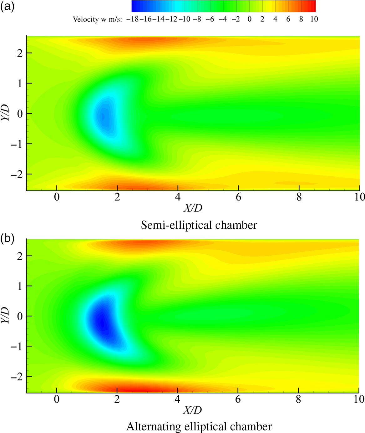
Figure 6. Z Velocity contour diagrams near the target wall of the impingement chambers.
3.2 Heat transfer performance
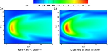
To reveal the influence of the alternating elliptical chamber on the heat transfer of a target surface, Fig. 7 shows the local Nusselt number distribution for the two kinds of chambers. For convenience of observation and comparison, the arc target surface has been expanded into a plane by arc length transformation. All lengths are dimensionless in terms of the impingement nozzle diameter. It can be seen that nucleate high heat transfer zones exist in both the semi-elliptical chamber and the alternating elliptical chamber. The nucleate high heat transfer zones correspond to the stagnation areas of the impingement jets.

Figure 7. Nu distribution at the target surface.
For the semi-elliptical impingement chamber, the maximum value of the Nusselt number on the target surface is 180, the stagnation point is X/D = 3 and the vertical projection position of the impact hole is X/D = 0, indicating that the impact jet is deflected by the cross flow. Downstream from the stagnation point, it can be observed that a wall jet is formed and the target Nusselt number gradually decreases. The alternating elliptical impingement chamber intensively enhances the heat transfer. At the same time, the high heat transfer areas move upstream and expand. Specifically, the maximum Nusselt number reaches 220, and the stagnation point moves upstream a distance of about the impingement nozzle diameter. Moreover, two high heat transfer zones appear on both sides of the upstream spread of the stagnation zone, which is due to the longitudinal vortices generated by the alternation of the cross section near the wall.
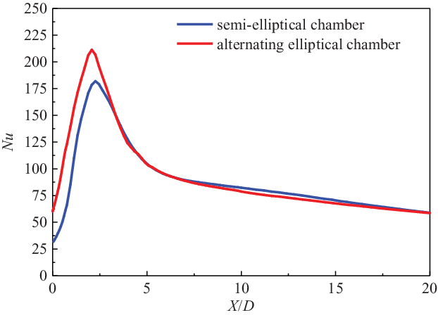
Figures 8 and 9 show the quantitative results for the Nusselt number distributions. Among them, Fig. 8 shows the Nusselt number distribution on the centreline of the target surface, and Fig. 9 demonstrates the span-wise averaged Nusselt number distributions. Overall, the alternating elliptical chamber increases the Nusselt number for both the centreline and the span-wise averaged distribution. Specifically, the alternating elliptical chamber raises the peak value of the Nusselt number from 180 to 220. More importantly, in the range of X/D = 0 to 3, the Nusselt numbers on the centreline are all increased by more than 30. In the range of X/D = 4 to 20, the Nusselt number distributions on the centreline of the two kinds of impingement chamber are almost the same. For the span-wise averaged Nusselt number, the maximum value of the semi-elliptical chamber is about 85, while for the alternating elliptical chamber, it is 95.

Figure 8. Nusselt number distribution on the target’s centreline.
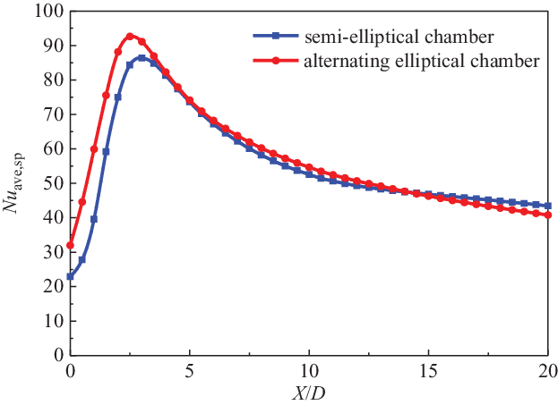
Figure 9. Span-wise averaged Nusselt number distribution.
3.3 Effects of cross-flow velocity ratio
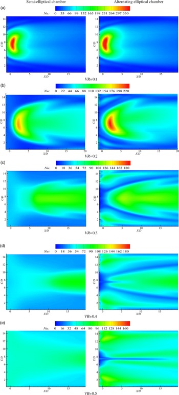
When the cross-flow velocity ratio, VR, is changed, the impingement velocity stays constant, 50m/s, and the cross-flow velocity is dependent on the cross-flow velocity ratio, which ranges from 0.1 to 0.5. Figure 10 shows the Nusselt number distributions for different cross-flow velocity ratios. It can be clearly observed that the Nusselt numbers decrease with an increase of the cross-flow velocity ratio for both the semi-elliptical chamber and the alternating elliptical chamber, and the stagnation point moves downstream gradually. However, with the increase of the cross-flow ratio, the Nusselt number distribution is also more uniform. The alternating elliptical chamber enhances the heat transfer and moves the stagnation point up for all cross-flow ratios, and the heat transfer enhancement effect becomes more obvious under high cross-flow velocity ratio. Specifically, when the cross-flow ratio is 0.1, the Nusselt number distribution of the alternating elliptical chamber is similar to that of the semi-elliptical chamber. Under a cross-flow ratio of 0.2, the peak Nusselt number is increased from 180 to 220 by the alternating elliptical chamber, as discussed in Sect. 3.2. With a further increase of the cross-flow ratio, the high heat transfer areas of the semi-elliptical chamber shrink sharply. For the elliptical chamber, the high heat transfer areas are obviously larger than for the semi-elliptical chamber. Furthermore, the Nusselt number in high heat transfer areas is increased by the longitudinal vortex, being even higher than that at the stagnation point, indicating that the longitudinal vortex has a greater effect on the heat transfer enhancement than the jet impingement at high cross-flow ratio.

Figure 10. Nu distribution for different VR.
3.4 Effects of cross-flow temperature ratio
The cross flow is developed from the spent coolant or the initial flow, so that the cross flow may have been heated by the target wall when it interacts with the impingement jet. However, the impingement jet has not been heated. In this section, the effects of the cross-flow temperature ratio on the heat transfer of impingement cooling are examined. In the simulation, the jetting flow temperature is kept constant at 350K, and the cross-flow velocity ratio is kept constant at 0.2. The cross-flow temperature is dependent on the temperature ratio, which ranges from 1.05 to 1.20. Figure 11 shows the Nusselt number distribution for different temperature ratios. From this figure, it can be seen that, with increasing cross-flow temperature ratio, the high heat transfer regions gradually shrink, and the peak Nusselt number also gradually decreases for both kinds of impingement chamber. This phenomenon is mainly due to the decrease of the temperature difference between the coolant and target wall. However, the alternating elliptical chamber enhances the heat transfer and moves the stagnation points up for all cross-flow temperature ratios.
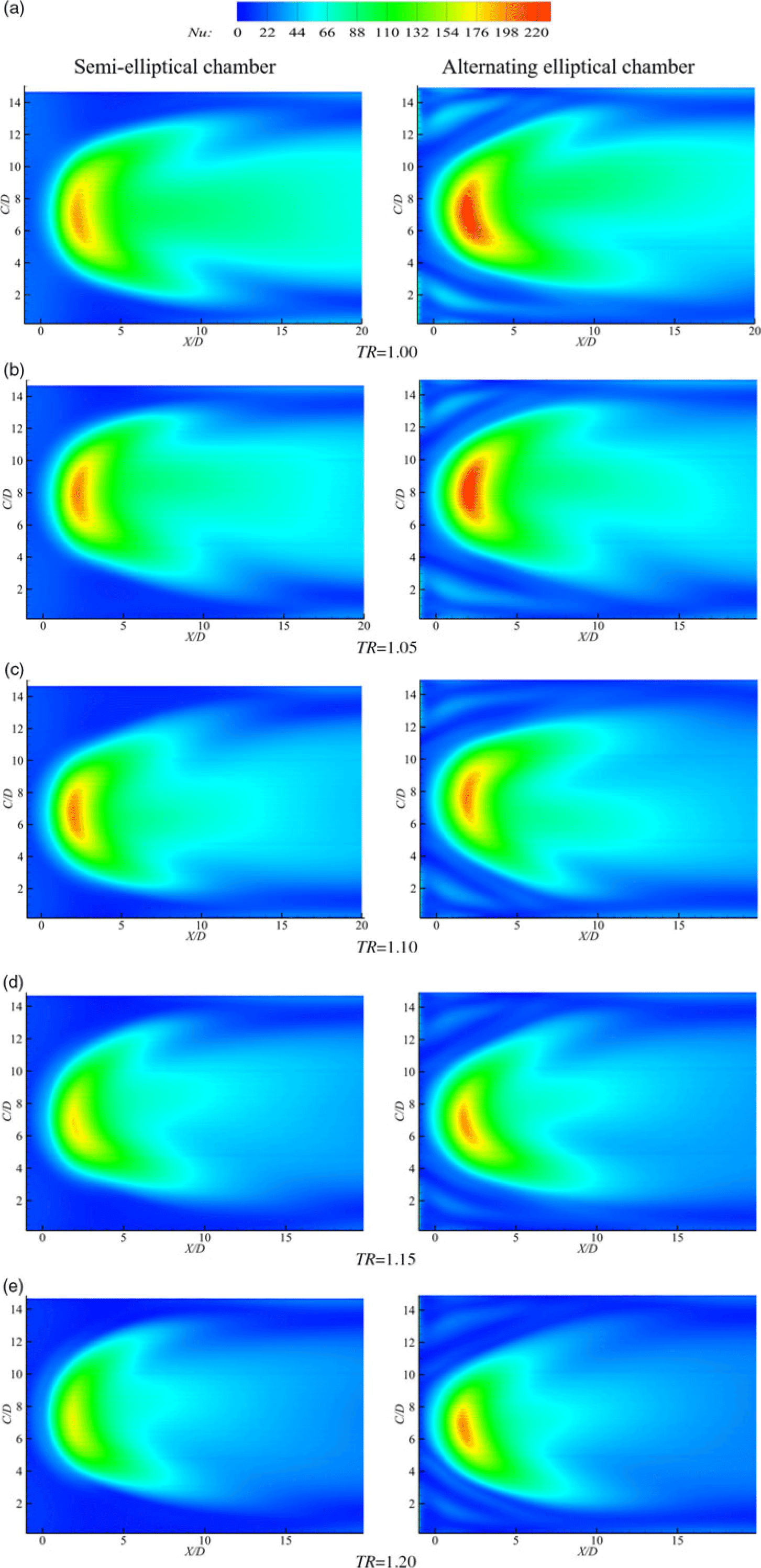
Figure 11. Nu distribution for different TR.
4.0 CONCLUSIONS
Numerical simulations are performed to investigate the cross-flow suppression and heat transfer enhancement of alternating elliptical impingement chambers. The influence of such alternation on the heat transfer and pressure loss is revealed by comparison with a straight semi-elliptical chamber. The following conclusions can be drawn:
-
(1) With respect to the flow field, in the semi-elliptical chamber, the flow direction in the cross section upstream of the impingement jet hole is opposite to the jet, while in the alternating elliptical chamber, due to the alternation of the cross section, a pair of longitudinal vortices that have the same direction as the jet in the centre of the chamber are generated. Thus, the penetration ability of the jet is enhanced and the penetrating depth is increased. Near the target surface, the jet velocity of the alternating elliptical chamber is larger, and the high-speed areas move upstream.
-
(2) With regard to heat transfer, the alternating elliptical chamber observably enhances the heat transfer of the target surface. The peak Nusselt number is increased from 180 to 220 when VR is equal to 0.2, and the high heat transfer zones expand.
-
(3) The change of the cross-flow ratio has an obvious effect on the heat transfer performance. The Nusselt number decreases with increasing VR for both the semi-elliptical chamber and the alternating elliptical chamber. The alternating elliptical chamber enhances the heat transfer and moves the stagnation points up for all the cross-flow velocity ratios and temperature ratios, and the heat transfer enhancement is more obvious at high cross-flow velocity ratio.
Acknowledgements
The authors would like to acknowledge financial support from the National Natural Science Foundation of China (grant no. 51876156).