


1. Introduction
The possibility of predicting the distribution of fracture network attributes has a primary importance in oil and gas research and development, particularly in fractured reservoirs (e.g. Nelson, Reference Nelson1985; Antonellini & Mollema, Reference Antonellini and Mollema2000; Aydin, Reference Aydin2000). This is the case for reservoirs located in the frontal portion of the Zagros Simply Folded Belt, where a substantial part of the porosity and, above all, permeability is provided by fractures (e.g. McQuillan, Reference McQuillan, Roehl and Choquette1985; Gholipur, Reference Gholipur1994). Owing to this, since the pioneering work of McQuillan (Reference McQuillan1973), many studies have focused on the description and interpretation of fracture patterns in analogue structures exposed in the belt (e.g. McQuillan, Reference McQuillan1974; Inger, Blanc & Hassani, Reference Inger, Blanc and Hassani2002; Wennberg et al. Reference Wennberg, Svånå, Azizzadeh, Aqrawi, Brockbank, Lyslo and Ogilvie2006; Stephenson et al. Reference Stephenson, Koopman, Hillgartner, McQuillan, Bourne, Noad, Rawnsley, Lonergan, Jolly, Rawnsley and Sanderson2007; Ahmadhadi et al. Reference Ahmadhadi, Daniel, Azzizadeh and Lacombe2008). These studies have documented the existence of two main fracture assemblages. The first one includes deformation structures striking roughly parallel (longitudinal) and perpendicular (transversal) to the hosting, mostly NW–SE-oriented, anticlines. The second assemblage includes elements striking roughly parallel and perpendicular to N–S-oriented inherited basement faults reactivated with right-lateral kinematics during the belt's evolution (e.g. Hessami, Koyi & Talbot, Reference Hessami, Koyi and Talbot2001). Although there is a general agreement on the fact that N–S- and E–W-oriented fractures are somehow related to the reactivation of N–S-striking basement faults (e.g. Stephenson et al. Reference Stephenson, Koopman, Hillgartner, McQuillan, Bourne, Noad, Rawnsley, Lonergan, Jolly, Rawnsley and Sanderson2007; Ahmadhadi et al. Reference Ahmadhadi, Daniel, Azzizadeh and Lacombe2008), the genetic link between folding, basement fault reactivation and fracture development, which is fundamental information for predicting fracture distribution within reservoir structures, is not yet completely understood.
In this work we describe and discuss the mesoscale deformation pattern of the Bangestan anticline. The analysis of the deformation pattern attributes (including fracture type, orientation and overprinting relationships) versus the position within a balanced cross-section of the structure obtained by integrating a reflection seismic line, well data and surface geology, allowed us to unravel both the meso- and macroscale deformational sequences. This in turn resulted in an understanding of the relationship between fold kinematics and mesoscale deformation patterns (e.g. Storti & Salvini, Reference Storti and Salvini1996; Thorbjornsen & Dunne, Reference Thorbjornsen and Dunne1997; Tavani et al. Reference Tavani, Storti, Fernandez, Munoz and Salvini2006). Such a relationship provides a predictive tool for linking fold kinematics and deformation pattern in reservoir structures of the Zagros Simply Folded Belt.
2. Geological setting
The Zagros fold-and-thrust belt forms part of the Arabia–Eurasia collisional margin (Fig. 1a). This tectonically active area (Jackson & McKenzie, Reference Jackson and McKenzie1984) provides an excellent example of compressional strain partitioning (e.g. Talebian & Jackson, Reference Talebian and Jackson2002; Blanc et al. Reference Blanc, Allen, Inger and Hassani2003), where N–S convergence (e.g. Sella, Dixon & Mao, Reference Sella, Dixon and Mao2002) is accommodated by reverse and right-lateral strike-slip movements along NW–SE-striking elements. The Zagros Belt is bounded to the NE by a complex NW–SE-striking fault system, consisting of two main segments: the Main Zagros Reverse Fault and Main Recent Fault, where reverse and right-lateral strike-slip movements coexist (e.g. Dewey et al. Reference Dewey, Pitman, Ryan and Bonnin1973; Dercourt et al. Reference Dercourt, Zonenshain, Ricou, Kazmin, Le Pichon, Knipper, Grandjacquet, Sbortshikov, Geyssant, Lepvrier, Pechersky, Boulin, Sibuet, Savostin, Sorokhtin, Westphal, Bazhenov, Lauer and Biju-Duval1986; Blanc et al. Reference Blanc, Allen, Inger and Hassani2003; McQuarrie, Reference McQuarrie2004). To the SW of this fault system, the High Zagros Fault represents the NE boundary of the Zagros Simply Folded Belt, which is formed by folds striking from E to W (eastern sector) to NW to SE (central and western sectors). N–S-trending lineaments divide the belt into different domains and represent the surface expression of inherited basement faults reactivated with right-lateral strike-slip kinematics during collision (e.g. Talbot & Alavi, Reference Talbot, Alavi, Blundell, Davison and Alsop1996, Hessami, Koyi & Talbot, Reference Hessami, Koyi and Talbot2001). The Zagros Simply Folded Belt is characterized by a strong decoupling between an upper thick sedimentary pile of Lower Cambrian to Pliocenic strata (e.g. Falcon, Reference Falcon and Kent1969) and the underlying basement (Fig. 1b), both of them being involved in the deformation (e.g. Jackson & Fitch, Reference Jackson and Fitch1981; Barberian, Reference Berberian1995; Molinaro et al. Reference Molinaro, Leturmy, Guezou, Lamotte and Eshraghi2005; Mouthereau, Lacombe & Meyer, Reference Mouthereau, Lacombe and Meyer2006, among others).
Figure 1. (a) Elevation map with main faults of the Arabia–Eurasia collisional margin marked. (b) Schematic stratigraphic sequence of the study area.
The Bangestan anticline is located to the east of the Dezful Embayment, close to the Izeh-Hendijan Fault (e.g. Ahmadhadi et al. Reference Ahmadhadi, Daniel, Azzizadeh and Lacombe2008), one of the major N–S-trending right-lateral strike-slip fault systems in the Zagros Simply Folded Belt (Figs 1a, 2a). Folded rocks include the basement and the overlying sedimentary cover (Figs 1b, 2b). The exposed portion of the multi-layer sedimentary cover is represented by Miocenic to Pliocenic siliciclastic (from the Mishan to Bakhtyari formations) and evaporitic (Gachsaran Formation) syn-tectonic sediments, overlying the Oligo-Miocene Asmari limestones. These, in turn, overlie Upper Cretaceous to Eocenic marls and marly clays of the Pabdeh and Gurpi formations. The underlying Bangestan Group includes limestones (Ilam and Sarvak formations) and clays and marls (Kazhdumi Formation) of Late and Early Cretaceous age, respectively. The underlying Lower Cretaceous limestones of the Dariyan Formation are the oldest exposed rocks and belong to the Khami Group.
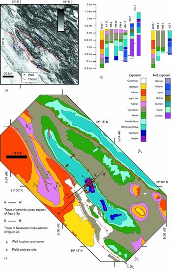
Figure 2. (a) Slope map with main faults of the study area and well locations marked. (b) Wells and colour codes for units. (c) Geological map of the Bangestan anticline with wells and field site locations marked.
Along and across-strike lengths of the study anticline are about 80 km and 10 km, respectively. The overall axial trend is about NW–SE; however, different segments strike from NNW–SSE to WNW–ESE (Fig. 2c). The fold is asymmetric and characterized by a narrow hinge zone dividing a southwestern forelimb (dipping from 20° to 90° toward the SW) and a northeastern backlimb. In the latter, layer dips range from 20° to 30° toward the NE in the Asmari Formation. In the underlying units, layers progressively reach a vertical attitude, becoming overturned in the central sector of the anticline. The basement depth in the area passes from 9 km to the SW of the anticline to 8 km to the NE (NIOC, unpub. report, 2010), indicating that it was involved in thrusting. The seismic cross-section (Fig. 3a), well data (Fig. 2b) and surface information allowed us to constrain the deep geometry of the structure (Fig. 3b). In our interpretation, the Bangestan anticline is a deeply rooted break-thrust fold (Fischer, Woodward & Mitchell, Reference Fischer, Woodward and Mitchell1992) characterized by a steeply dipping low-displacement backthrust splaying off from the bottom of the Dashtak Formation in the forelimb. The forelimb is interpreted to have developed by the positive inversion of a Cambrian extensional fault zone. A wedge-shaped tectonic slice occurs in the footwall of the Bangestan anticline, likely originated by a shortcut thrust during contractional buttressing against the inherited extensional fault zone (Fig. 3b). This major forethrust is highlighted in the southwestern side of the seismic section by the juxtaposition of NE- and SW-dipping panels in the footwall and hangingwall, respectively (Fig. 3a). Finally, a more gentle anticline occurs to the SW, detached above the Hormuz evaporites. The geometry of this frontal structure is quite speculative, being constrained by mostly surface data.
The restored cross-section (Fig. 3c) shows that the Dashtak and Hormuz formations divided three sectors characterized by rather constant line lengths. This is due to the assumption of an early décollement folding stage, during which both these units acted as ductile horizons thickening in the core of the anticline. In our reconstruction, this early anticline accommodated the displacement associated with a deeper and more internal structure. This scenario is supported by the observation that, in the study area, the Dashtak Formation frequently displays a significant thickening in the core of anticlines and it is considered, together with the Hormuz Formation, an efficient detachment level (e.g. Sherkati & Letouzey, Reference Sherkati and Letouzey2004). The computed amount of shortening is about 6.7 km in the upper stratigraphic levels and 4.4 km in the lower portion of the cover, reducing to 3.4 km in the basement. These values, particularly in the lower sectors of the anticline, arise from the assumptions that the basement fault is a steeply dipping reworked normal fault. Moreover, insights provided by the seismic line, together with surface and well data, allow us to strongly constrain the shallower geometries of the anticline. On the contrary, the amount of shortening in the deeper portion of the anticline was computed by assuming bed-thickness and line-length preservation (with the exception of ‘ductile’ units), thus flexural-slip folding. The assumption of this typically ‘brittle’ deforming mechanism in the deeper portion of the fold was dictated by the necessity of providing at least a first-order picture of this portion of the anticline. However, this strong mechanical oversimplification affects the quality of results and, accordingly, the amounts of shortening have to be regarded as first-order values.
3. Fracture data
Data about fracture type, orientation, cross-cutting relationships and orientation of the reference bedding have been collected in 53 field sites, mostly located in the central portion of the anticline (Fig. 2c) and in the multi-layer cover sediments of the Dariyan to Asmari formations.
Although they are not particularly abundant, pressure solution cleavages occur in all the lithologies, from the Dariyan to Asmari. They mostly form at a high angle to bedding and strike about NW–SE (Figs 4a, 5a). Stylolitic teeth, when well developed, are perpendicular to the cleavage plane (Fig. 5a), with a few exceptions (possibly indicating a later re-working) discussed later in the text. In the steeper sectors of both limbs a second set is present, oriented at a low angle to bedding (Fig. 5b, c), overprinting all the structural fabrics lying at a high angle to bedding. Joints and veins are the most abundant elements. They are oriented at a high angle to bedding and, once the bedding is restored to the horizontal, these deformation structures are clustered about four maxima striking N5°E, N50°E, N100°E and N135°E (Fig. 4b). Fault orientation is much more scattered than the other deformation structures (Fig. 4c). Only a few slickenlines were found along the fault planes and their kinematics have been mostly constrained by their associated deformation pattern or by displaced markers (i.e. bedding surface and previously developed mesostructures). This implies that kinematical information is, in the most part, semi-quantitative and cannot be easily plotted. For this reason in Figure 4 we only provide the contouring of poles to faults with a description of the kinematics of each fault set. More detailed information about the fault kinematics is provided in the subsequent figures. Once the bedding dip is restored to the horizontal, the main fault set is represented by left-lateral faults near perpendicular to bedding and striking about N80°E. These faults commonly occur in association with longitudinal pressure solution cleavages, N50°E-striking joints and veins, and with a set of bedding-perpendicular right-lateral strike-slip faults striking from N10°E to N30°E (Fig. 5a). Faults striking from N30°E to N60°E and dipping 50–60° toward the SW have extensional kinematics. Faults striking about NW–SE mostly have right-lateral strike-slip shear sense and, very subordinately, an extensional one. The residual dataset includes faults striking about NNW–SSE (partially including bedding surfaces reworked as faults), mostly occurring in the near-vertical forelimb and in the near-vertical to overturned backlimb. These faults, together with the low angle to bedding pressure solution cleavages, represent the damage zone of map-scale thrust faults (Fig. 6).

Figure 4. Cumulative contouring, in the present orientation and after restoring the bedding dip to the horizontal, of: (a) poles to pressure solution cleavages; (b) poles to joints and veins; (c) poles to faults.

Figure 5. (a) View of a bedding surface in the Dariyan Formation with longitudinal pressure solution cleavages, transversal veins and conjugate strike-slip faults. The line-drawings in the insets from 1 to 7 show the cross-cutting relationships between the different elements. Transversal veins pre-date the other elements (insets 1, 3, 4); pressure solution cleavage and ENE–WSW-striking left-lateral faults display ambiguous cross-cutting relationships (insets 2, 4, 5); NNE–SSW-striking right-lateral faults exhibit negligible displacements and postdate the other elements (insets 6 and 7). (b) Photo and (c) line-drawing of reverse faults with associated pervasive pressure solution cleavages. The pressure solution cleavages abut against the faults and form an angle of about 45° with them. This indicates that cleavage is fault-related and that the faults are reverse, with a top-to-NE shear sense.

Figure 6. Photo of an overturned bedding surface reworked as a fault, with associated synthetic and antithetic faults, in the overturned backlimb; Bangestan Group. The SW-dipping bedding surface has no associated slickenlines; however, the surrounding rock mass is characterized by pervasive fracturing (left side of the photo), with fractures organized in two sets, both of them terminating on the bedding. Fracture sets form angles of 20–25° and 75–80° with the bedding surface and an angle of about 55° between them. All these observations support the idea that the fracture sets are, as previously mentioned, synthetic and antithetic faults belonging to the damage zone of the re-worked bedding surface.
In the following Sections the deformation pattern in different positions in the anticline is described for each exposed calcareous unit.
3.a. Asmari Formation
The Asmari Formation is exposed on both fold limbs. The deformation pattern in the forelimb includes two joint sets perpendicular to bedding. Once the bedding dip is removed they strike about N–S and E–W (Fig. 7a). Mutual cross-cutting relationships indicate that the two sets are roughly coeval (Fig. 7b). The deformation pattern in the backlimb, where the bedding dip in the Asmari Formation ranges from 20° to 30° toward the NE, is much more complex. Once the bedding dip is removed it includes conjugate reverse faults striking NW–SE, NW–SE-striking pressure solution cleavages perpendicular to bedding, joints and extensional faults striking NE–SW (i.e. perpendicular to both pressure solution cleavage and reverse faults) and joints striking from NW–SE to NNW–SSE (Fig. 7c). The latter joints are locally reworked as left-lateral strike-slip faults with implosion breccias (Fig. 7d, e) and oil seeps along NW–SE-striking longitudinal joints (Fig. 7f). Pressure solution cleavages postdate the NE–SW-striking joint/vein set and are overprinted by NW–SE-striking joints.

Figure 7. Deformation pattern in the Asmari Formation. (a) Deformation pattern, after bedding dip removal, in both the forelimb and backlimb of the anticline. (b) Ambiguous cross-cutting relationships between N–S- and E–W-striking joints in the forelimb, indicating synchronous development. White arrows show N–S-striking joints arresting on an E–W-striking joint; black arrow shows an opposite cross-cutting relationship. (c) Longitudinal bedding-perpendicular stratabound joints in the backlimb. (d) Photo and (e) schematic line-drawing of implosion breccias (developed along previous longitudinal joints) in the vicinity of a NNW–SSE-striking left-lateral faults. (f) Longitudinal joints filled by hydrocarbons along the northern projection (about 20 m) of the system in (d). (g) Schematic drawing of the system in (d) and (e).
3.b. Ilam and Sarvak formations
These formations are exposed in the forelimb, in the crest and in the near-vertical to overturned backlimb. In the northern part of the anticline (Fig. 2c), the forelimb is characterized by the presence of a highly deformed area, possibly associated with the tip of a backthrust, where the deformation pattern includes near-vertical to SW-dipping pressure solution cleavages and reverse faults (Fig. 5b, c). Both of them strike NW–SE, regardless of the bedding dip (Fig. 8). The deformation degree is very strong and, owing to this, other structural assemblages cannot be recognized.

Figure 8. Deformation pattern in the Ilam and Sarvak formations. The deformation pattern associated with backthrust in the forelimb is displayed in its present orientation. The deformation pattern in the near-vertical to overturned backlimb is displayed in both present orientation and after bedding dip removal. The other plots display the deformation pattern in the forelimb and in the crest after bedding dip removal.
To the south of this area the deformation pattern in the forelimb becomes less pervasive and similar to that observed in the Asmari Formation (Fig. 8). It includes N–S- and E–W-striking joints. These are near perpendicular to bedding when they are stratabound. Non-stratabound joints with similar strikes have a near-vertical attitude regardless of bedding dip (Fig. 9). In this area NW–SE-striking pressure solution cleavages occur and are near perpendicular to bedding. Moreover, a third joint set (frequently filled by calcite) perpendicular to bedding and striking about NE–SW was recognized. Faults mostly have reverse kinematics, with a transport direction toward the NE. The N–S-striking joints are frequently reworked as right-lateral strike-slip faults. Systematic cross-cutting relationships occur between the E–W- and NE–SW-striking joint sets, with the former postdating the latter.

Figure 9. Photo of near-vertical, non-bedding-perpendicular, N–S-striking ‘fractures’ in the forelimb of the anticline; Bangestan Group. In the upper portion, the rock mass is poorly layered and ‘fractures’ are near vertical. On the contrary, in the lower portion (central part of the photo) the rocks are well-layered and ‘fractures’ become bedding perpendicular.
In the crestal sector of the anticline, the deformation pattern includes two fault sets (Fig. 8): N120°-striking right-lateral strike-slip faults, and NE–SW-striking extensional faults. Joints include three sets striking NE–SW, WNW–ESE and NW–SE, respectively, the former being the older ones.
In the near-vertical to overturned backlimb, when bedding dip is restored to the horizontal, joints strike NE–SW and, subordinately, N–S (Fig. 8). Pressure solution cleavages are both at low and high angles to bedding. Pressure solution cleavages at a high angle to bedding strike, when bedding is restored to the horizontal, from NNW–SSE to NW–SE. Poles to faults are clustered along a roughly WSW–ENE-oriented direction. Their kinematics, in both present orientation and after bedding dip removal, is both extensional and reverse. However, the abundance of pressure solution cleavages, which occur not only close to faults, suggests that in this area the tectonic framework is compressional.
3.c. Dariyan Formation
The deformation pattern in the Dariyan Formation exposed in the forelimb includes NW–SE-striking pressure solution cleavages near perpendicular to bedding and, subordinately, E–W-striking ones (Fig. 10). Joints are clustered in two sets that are near perpendicular to bedding and strike NW–SE and NE–SW, respectively. Faults strike N–S and E–W and are near vertical (and oblique to bedding). A third fault set is represented by NW–SE-striking joints reworked as right-lateral strike-slip faults (Fig. 11a, b). This reworking led to the development of pressure solution cleavages striking E–W, and to the reworking of the older NW–SE-striking pressure solution cleavages which formed N–S-oriented stylolitic teeth (Fig. 11b). Implosion breccias are associated with the strike-slip reactivation of NW–SE-striking joints (Fig. 11c, d). In the crestal sector of the anticline, joints are near vertical and clustered about four maxima striking WNW–ESE, NW–SE, NNW–SSE and NE–SW, respectively (Fig. 10). N–S-striking right-lateral strike-slip faults are also present. NW–SE-striking joints are, in many cases, reworked as right-lateral strike-slip faults. In the near-vertical backlimb two roughly E–W-striking joint sets are present. After bedding dip removal, their strike becomes about E–W and N–S. E–W-striking bedding-perpendicular pressure solution cleavages also occur.

Figure 10. Deformation pattern in the Dariyan Formation.

Figure 11. (a) Photo of a bedding surface in the Dariyan Formation with a longitudinal right-lateral fault and associated strike-slip duplexes. (b) Detail of E–W- (white arrows) and NW–SE-striking (black arrows) pressure solution cleavages. Both cleavages are characterized by N–S-oriented stylolitic teeth, indicating that N–S shortening postdates the development of NW–SE-striking cleavages. (c) Longitudinal right-lateral fault with detail of the associated implosion breccia (d).
4. Structural summary
The deformation pattern observed in the Bangestan anticline can be chronologically and kinematically organized into four structural assemblages (Fig. 12).

Figure 12. Schematic map view and inferred stress fields of the structural assemblages found in the Bangestan anticline. See text for details.
4.a. Assemblage 1
Assemblage 1 occurs in all the lithologies and structural positions and includes (Fig. 12a) (1) bedding-perpendicular transversal joints and veins striking about NE–SW; (2) bedding-perpendicular longitudinal pressure solution cleavage striking about NW–SE; and (3) conjugate strike-slip faults near perpendicular to bedding. Right-lateral and left-lateral strike-slip faults strike about NNE–SSW and WSW–ENE, respectively, and have acute intersection angles ranging from 50° to 80°. The bisectors of the intersection angles are parallel to the transversal deformation structures.
Deformation structures belonging to assemblage 1 are the oldest and, particularly, NE–SW-striking joints were the first to develop. A stress field having σ1 and σ3 parallel to bedding and striking, respectively, perpendicular and parallel to the axial trend of the Bangestan anticline can be inferred from assemblage 1, indicating an event of NE–SW-oriented layer-parallel shortening (LPS) and NW–SE extension (Fig. 12a).
4.b. Assemblage 2
The second assemblage includes joints near perpendicular to bedding and, very subordinately, extensional faults, both of them striking roughly parallel to the fold axial trend (Fig. 12b). Elements of assemblage 2, which occur in all the lithologies and structural positions, postdate assemblage 1. Deformation structures of assemblage 2, particularly the longitudinal joints, are frequently reworked as right-lateral strike-slip faults (Fig. 11). A stress field having σ3 and σ2 parallel to bedding and striking, respectively, perpendicular and parallel to the axial trend of the Bangestan anticline can be inferred from assemblage 2 (Fig. 12b).
4.c. Assemblage 3
Assemblage 3 includes N–S- and E–W-striking synchronous tensile structures (joints and veins) (Fig. 12c), which were frequently reactivated as strike-slip faults. They occur in all the lithologies and structural positions and mostly postdate assemblage 1. However, in few cases, transversal joints arrest on either N–S- or E–W-striking pre-existing joints, particularly when they display a strike-slip reactivation (Fig. 13). The stress field responsible for the development of these deformation structures was characterized by a near-vertical σ1, which was not perpendicular to bedding. The orientation of σ3 and σ2 cannot be constrained (Fig. 12c).

Figure 13. Photo of a bedding surface in the forelimb with transversal joints (white arrows) and E–W- (grey arrows) and N–S-striking (black arrows) elements. E–W- and N–S-striking elements are mostly joints; however, many of them (particularly the N–S-striking ones) display evidence of strike-slip reactivation. The interpretation, which explains the ambiguous cross-cutting relationships, is that the reactivation of N–S-striking elements as right-lateral faults caused their propagation (with negligible associated displacements) and the coeval reactivation (and propagation) of both NW–SE- and E–W-striking structures.
4.d. Assemblage 4
Deformation structures belonging to assemblage 4 include reverse faults and pressure solution cleavages at a low angle to bedding, as those described in Figures 5b and 6. This assemblage occurs in two highly deformed areas, located in the forelimb and in the near-vertical to overturned backlimb and postdates the other deformation structures. This assemblage represents the damage zone of map-scale thrusts which have developed after/during bed tilting and fold tightening (Fig. 12d).
5. Discussion
5.a. Timing of mesoscale deformation development
The first evidence arising from our observations is the abundance of joint and vein sets frequently displaying ambiguous cross-cutting relationships. This can be related to the fact that mesoscale mechanical discontinuities can alter the local state of stress (e.g. Bergbauer & Pollard, Reference Bergbauer and Pollard2004) and/or to a variability in cohesion contrasts along pre-existing deformation structures that determine whether younger tensile fractures cross-cut or abut against them (e.g. Lash & Engelder, Reference Lash and Engelder2009). Having introduced this cautionary note, it is evident that assemblages 1 and 4 are the oldest and youngest, respectively. Transversal structures belonging to assemblage 1 (i.e. NW–SE-striking joints and veins) are, in fact, very frequently postdated by the other elements, as also observed in this area by Ahmadhadi et al. (Reference Ahmadhadi, Daniel, Azzizadeh and Lacombe2008). As previously reported, a few exceptions are observed mostly in the presence of N–S-striking right-lateral faults, where the optimal orientation of transversal structures with respect to the right-lateral faults (i.e. about 45°) would have determined their extensional reactivation. On the other hand, assemblage 4 is clearly late folding. In fact, it developed both during and after the tilting of steeply dipping layers, where we observed that all the other structures have been clearly tilted together with the beds.
The relationships between N–S- and E–W-striking joints, longitudinal joints and strike-slip movements are, on the contrary, unclear. Stephenson et al. (Reference Stephenson, Koopman, Hillgartner, McQuillan, Bourne, Noad, Rawnsley, Lonergan, Jolly, Rawnsley and Sanderson2007) suggested that N–S and E–W elements formed, in this area, in response to the reactivation of inherited N–S- and E–W-striking basement faults, which postdated the longitudinal jointing. Conversely, Ahmadhadi et al. (Reference Ahmadhadi, Daniel, Azzizadeh and Lacombe2008), who also highlighted the directional reactivation of previously formed joint sets, suggested the possibility of a rather synchronous development of N–S and longitudinal elements, which would be related to flexures induced by the reactivation of N–S- and NW–SE-striking basement structures. In the study area we observed that N–S- and E–W-striking joints are rather synchronous and locate also in the NW–SE-striking fold sectors. Moreover, N–S-striking joints are near perpendicular to bedding when they are stratabound. When their height exceeds some metres they become near vertical (when bedding dip is about 20–30°). Such a behaviour is not observed for longitudinal extensional elements. These observations suggest that longitudinal joints have developed prior to N–S- and E–W-striking ones, during a pre- to early-folding stage. N–S- and E–W-striking deformational structures would have developed during an early- to post-folding stage.
It must be highlighted that our chronological reconstruction is based on the assumption that the strike-slip event is responsible for some anomalous cross-cutting relationships, namely N–S-striking elements pre-dating both transversal (i.e. NE–SW-striking) and longitudinal (i.e. NW–SE-striking) extensional elements. The same cross-cutting relationships have been documented by Lacombe, Bellahsen & Mouthereau (Reference Lacombe, Bellahsen and Mouthereau2011, this issue) in the Fars region, where NNE–SSW-striking extensional elements display ambiguous cross-cutting relationships with the layer-parallel shortening pattern. These authors proposed the existence of three compressional stages, characterized by a maximum stress component oriented NNE–SSW, NE–SW and, again, NNE–SSW. The hypothesis of an early compressional stage having a NNE–SSW-oriented shortening direction cannot be discarded in the Bangestan anticline; however, the majority of N–S- and E–W-striking elements would have developed in the younger roughly N–S-directed compressional stage. Right-lateral reworking of NW–SE-striking elements, development of E–W-striking pressure solution cleavages and N–S-striking joints, and development of N–S-oriented stylolitic teeth along previously developed NW–SE-striking pressure solution cleavages, could have been induced by the rotation of the regional compression direction, from NE–SW to NNE–SSW. However, the presence of E–W-striking joints, synchronous to the N–S-striking ones requires an additional ‘contribution’.
5.b. Fold evolution from fracture patterns
Structural assemblages 1 and 2 include deformation structures roughly coaxial with the fold axial trend and represent the ‘classical’ deformation pattern observed in thrust-related anticlines (e.g. Stearns, Reference Stearns and Riecker1968; Price & Cosgrove, Reference Price and Cosgrove1990; Cooper, Reference Cooper and McClay1992; Engelder & Peacock, Reference Engelder and Peacock2001; Tavani et al. Reference Tavani, Storti, Salvini and Toscano2008; Amrouch et al. Reference Amrouch, Lacombe, Bellahsen, Daniel and Callot2010) (Fig. 14a, b). Structural assemblage 3 includes N–S- and E–W-striking extensional structures formed in response to a stress field having a near-vertical σ1 and both σ2 and σ3 oriented oblique to the fold axial trend. Occurrence of such extensional structures does not depend on the along-strike fold axis orientation, thus requiring a ‘regional’ cause rather than a local one. A consistent explanation for the development of assemblage 3 involves the presence of an axis-parallel right-lateral strike-slip component during the later stages of fold growth. Activation of a NW–SE-oriented right-lateral strike-slip component induces a local stress field characterized by a N–S-striking principal stress axis (e.g. Sylvester, Reference Sylvester1988) that is favourably oriented for the extensional re-activation of N–S-trending inherited brittle deformation features and for the formation of new ones. In such a kinematic framework, development of E–W-trending tensile structures can be explained by temporary re-orientations of the local stress field induced by failure along N–S joints and/or extensional faults, i.e. the mechanisms commonly proposed for the formation of cross-joints (e.g. Gross, Reference Gross1993; Bai et al. Reference Bai, Maerten, Gross and Aydin2002) (Fig. 14c). The lack of a dramatic drop in cohesion after failure can explain the mutual cross-cutting relations between E–W and N–S joints (Lash & Engelder, Reference Lash and Engelder2009). Development of near-vertical non-stratabound N–S-trending joints cutting through folded beds fits well into the proposed scenario. The observation that structural assemblage 4 is consistent with NW–SE contraction suggests that transpressional strain partitioning (e.g. Oldow, Bally & Avé Lallemant, Reference Oldow, Bally and Avé Lallemant1990) may have occurred in the final stage of fold tightening, with reverse and strike-slip movements accommodated by slip along major thrusts and diffuse deformation in the hangingwall.
Figure 14. Schematic evolution of the Bangestan anticline and hosted mesoscale deformation pattern. See text for details.
Summarizing, the deformation pattern recognized in the Bangestan anticline implies two major evolutionary stages of fold growth (Fig. 14). In the first stage, décollement folding involving the Cambrian to Miocenic sedimentary cover started in the hangingwall of an inherited pre-Cambrian extensional fault system, due to buttressing against the fault footwalls. The Hormuz salt represented the basal décollement and the folds developed in a right-stepping array (Fig. 14a). Folding was pre-dated by the development of a layer-parallel shortening deformation pattern and accompanied by the development of longitudinal extensional structures (Fig. 14b). The second evolutionary step was characterized by the transition to thick-skinned tectonics with transpressional reactivation of the inherited basement faults and the subsequent linkage of the overlying related fold segments to form the Bangestan anticline. The deformation pattern developed during this stage included E–W- and N–S-striking extensional structures. Continued deformation caused the right-lateral reactivation of longitudinal joints and, locally, of E–W- and N–S-striking deformation structures (Fig. 14c). Such a reconstruction matches the regional framework proposed by Molinaro et al. (Reference Molinaro, Leturmy, Guezou, Lamotte and Eshraghi2005), who support, at the regional scale, the transition from thin- to thick-skinned tectonics.
An alternative explanation invokes the rotation of the regional compression direction. As previously mentioned, the reconstructed deep geometry of the Bangestan anticline is based on many assumptions. If these are released, solutions implying a rather synchronous deformation of both cover and basement are possible (in agreement with regional observations by many authors; e.g. Mouthereau et al. Reference Mouthereau, Tensi, Bellahsen, Lacombe, De Boisgrollier and Kargar2007). In this second hypothesis, the tectonic style (i.e. thick-skinned) stays constant through time. Accordingly, the counter-clockwise rotation of the regional stress field (e.g. Lacombe, Bellahsen & Mouthereau, Reference Lacombe, Bellahsen and Mouthereau2011), is the only mechanism that can be invoked to explain the two-step evolution of the deformation pattern.
6. Conclusions
In this work we have presented and discussed the deformation pattern of the Bangestan anticline and its relationship to the evolution of the hosting structure. The structure started to grow from right-stepping, isolated décollement anticlines striking about NW–SE and involving the Palaeozoic to Tertiary sedimentary pile buttressed against the footwall of Precambrian extensional faults. This stage was pre-dated by the development of a layer-parallel shortening mesostructural deformation pattern, which includes NW–SE-striking pressure solution cleavages; NE–SW-striking joints and veins; and conjugate strike-slip faults. Progressive folding led to the development of longitudinal joints and extensional faults. Positive inversion of the deep basement faults caused the transition to thick-skinned tectonics leading to the linkage of the previously developed isolated folds into the actual Bangestan anticline. This stage was characterized by the presence of a right-lateral transpressional component, which led to the reactivation of previously developed longitudinal joints, and the development of N–S- and E–W-striking joints and veins that, in turn, were partially reactivated as strike-slip fault segments. Despite this solution well fitting our observations, an alternative solution is possible, invoking synchronous deformation of both basement and cover, and a counter-clockwise rotation of the compression direction explaining the two-step evolution of the deformation pattern.
Owing to the polyphase deformation history, from Precambrian extension to Cenozoic contraction and transpression, the evolution of the Bangestan anticline produced a fracture pattern that is more complex than what is expected in ‘classical’ thrust-related anticlines. This complexity is expected to improve fracture connectivity and could potentially have a significant impact on fluid flow and hence major implications for hydrocarbon exploration and production. This supports the importance of systematically performing field analogue studies for obtaining structural information, which could be implemented in predictive reservoir models.
Acknowledgements
Comments and suggestions from Nicolas Bellahsen and Ben Stephenson allowed us to improve an early version of the manuscript. This work was carried out with the financial support of the OMV, NIOC, Repsol-YPF, the MODES-4D (CGL2007-66431-C02-125 02/BTE) project and the ‘Grup de Recerca de Geodinàmica i Anàlisi de Conques’ (2001SRG-126 000074). 2DMove was used to build the cross-section of Figure 3b.


