


INTRODUCTION
The lateral fast electron transport at the target surface irradiated by intense laser pulses has attracted great attention because of the important role it plays in the cone guided scheme for fast ignition of inertial confinement fusion (Kodama et al., Reference Kodama, Norreys, Mima, Dangor, Evans, Fujita, Kitagawa, Krushelnick, Miyakoshi, Miyanaga, Norimatsu, Rose, Shozaki, Shigemori, Sunahara, Tampo, Tanaka, Toyama, Yamanaka and Zepf2001). Theoretical works have shown that the conical target can both guide the laser light and the fast electrons to the tip of the cone, which leads to an enhancement of the fast electron density near the cone tip (Sentoku et al., Reference Sentoku, Mima, Ruhl, Toyama, Kodama and Cowan2004; Nakamura et al., Reference Nakamura, Kato, Nagatomo and Mima2004). Li et al. (Reference Li, Yuan, Xu, Zheng, Sheng, Chen, Ma, Liang, Yu, Zhang, Liu, Wang, Wei, Zhao, Jin and Zhang2006b) and Habara et al. (Reference Habara, Adumi, Yabuuchi, Nakamura, Chen, Kashihara, Kodama, Kondo, Kumar, Lei, Matsuoka, Mima and Tanaka2006) have experimentally observed the fast electron beam emitting along the target surface into vacuum when the laser incidence angle is large. The observation of fast electrons transporting inside the conical target with K α imaging technique does not show obvious fast electron current along the inner wall of the conical target and the enhancement of the energy deposition near the cone tip. It is believed that the preplasma filling inside the cone, created by the prepulse and the pedestal of the intense laser pulse, inhibits the fast electron transport to the cone tip (Baton et al., Reference Baton, Koenig, Fuchs, Benuzzi-Mounaix, Guillou, Loupias, Vinci, Gremillet, Rousseaux, Drouin, Lefebvre, Dorchies, Fourment, Santos, Batani, Morace, Redaelli, Nakatsutsumi, Kodama, Nishida, Ozaki, Norimatsu, Aglitskiy, Atzeni and Schiavi2008; Van Woerkom et al., Reference Van Woerkom, Akli, Bartal, Beg, Chawla, Chen, Chowdhury, Freeman, Hey, Key, King, Link, Ma, Mackinnon, Macphee, Offermann, Ovchinnikov, Patel, Schumacher, Stephens and Tsui2008). Recently, the K α imaging measurement of a simple planar target foil with a preplasma irradiated by intense femtosecond (fs) laser pulses indicates that the fast electrons can laterally drift in the preplasma and deposit energy far away from the focal spot, due to the self-generated electrostatic field (E field) and magnetic field (B field) generated by the non-collinear gradients of electron temperature and density (Yabuuchi et al., Reference Yabuuchi, Paradkar, Wei, King, Beg, Stephens, Nakanii, Hatakeyama, Habara, Mima, Tanaka and Larsen2010; Lin et al., Reference Lin, Li, Liu, Liu, Du, Wang, Lu, Chen, Zhang, Liu, Wang, Liu, Liu, Wang, Ma, Wei and Zhang2010).
In this work, the lateral fast electron transport at the front target surface of a planar Cu foil as a function of laser incidence angle, when a preplasma is formed, is studied by K α imaging technique and electron spectrometer. When the incidence angle is 70°, a horizontally asymmetric K α halo structure is observed, corresponding to directional lateral fast electron transport and energy deposition at front target surface. Furthermore, the surface fast electron spectrum has a high energy tail with an electron temperature T hot ~ 1.6 MeV, which is much higher than the 45° case. It is believed that the deformation of the preplasma and the spatial distribution of the self-generated magnetic field are responsible for the directional lateral electron transport.
EXPERIMENTAL SETUP
The experiments were performed at the Institute of Physics, Chinese Academy of Sciences, using the Xtreme Light II (XL-II) Ti: sapphire laser system, which can deliver a linearly-polarized pulse with energy up to 0.6 J in 60 fs at 800 nm (Zhang et al., Reference Zhang, Li, Sheng, Wei, Dong and Lu2005). The p-polarized laser pulse was focused onto a 50 µm thick Cu foil target at incidence angle of 45° or 70° with an f/3.5 off-axis parabolic mirror. The diameter of the focal spot was about 4.5 µm at the full width at half maximum, in which contained about 35% of the laser energy. The laser intensity was up to 5 × 10¹⁸ W/cm2. The amplified spontaneous emission (ASE) was measured to be about 10−5 at about 10 ps before the peak of the main pulse. A prepulse, split from the main pulse, with similar focal spot to that of the main pulse, was used to generate a preplasma. The intensity of the prepulse was about 1016 W/cm2. The delay time, Δt, between the prepulse and the main pulse was about 0.6 ns.
Spherically bent quartz 2131 crystal was used to image the Cu K α emission at 8.048 keV onto a 16 bit charge-coupled device with a magnification of about 8. The radius of curvature of the crystal was 380 mm. A 30 mm diameter aperture was put in front of the crystal, giving an astigmatism-limited spatial resolution about 19 µm (Koch et al., Reference Koch, Aglitskiy, Brown, Cowan, Freeman, Hatchett, Holland, Key, Mackinnon, Seely, Snavely and Stephens2003). The energy bandwidth was about 11 eV (Akli et al., Reference Akli, Key, Chung, Hansen, Freeman, Chen, Gregori, Hatchett, Hey, Izumi, King, Kuba, Norreys, Mackinnon, Murphy, Snavely, Stephens, Stoeckel, Theobald and Zhang2007). The crystal viewed the K α emission at an angle of 48° with respect to the front target normal. A calibrated electron magnetic spectrometer with 1000 G permanent magnets was used to measure the energy spectrum of the out-going electrons at about 10° with respect to the front target surface.
RESULTS AND DISCUSSIONS
Figures 1a and 1b show the typical K α images taken for laser incidence angle of 45° and 70°, respectively. The laser pulse is incident from the left in the images. The energy of the main laser pulse is about 280 mJ for the two cases.
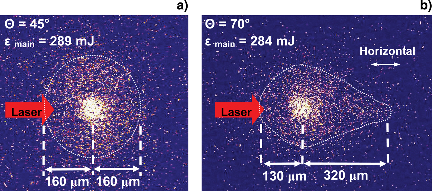
Fig. 1. (Color online) Typical K α images taken at the laser incidence angle of (a) 45° and (b) 70°. ɛmain is the main laser energy, θ is the laser incidence angle. The laser is incident from the left.
Several features can be seen from the images. A large K α halo structure surrounding the central spot is observed for both cases. This halo, which has been investigated in our previous work (Lin et al., Reference Lin, Li, Liu, Liu, Du, Wang, Lu, Chen, Zhang, Liu, Wang, Liu, Liu, Wang, Ma, Wei and Zhang2010), is mainly excited by the fast electrons laterally transporting in the self-generated E and B fields in the preplasma and depositing energy far away from the central focal spot. The most striking feature in Figure 1 is that the pattern of the halo is dependent on the laser incidence angle, θ. When θ is 45°, the halo is almost symmetrically distributed surrounding the central spot, with a radius of about 160 µm. In contrast, for the 70° case, the halo becomes asymmetric in the horizontal direction. The size of the right side of the halo reaches about 320 µm, which is about two times larger than the left side and that of the 45° case.
Figure 2 shows the energy spectra of fast electrons emitted into vacuum close to the direction parallel to the target surface, when θ is 45° and 70°, respectively. The electron spectra are fitted by the exponential distribution function (Li et al., Reference Li, Zhang, Chen, Mu, Liang, Wei, Dong, Chen, Teng, Chun-Yu, Jiang, Zheng and Tang2001), to estimate the fast electron temperature T hot. For the 45° case, T hot is 276 keV, which is close to the value by Beg's (Reference Beg, Bell, Dangor, Danson, Fews, Glinsky, Hammel, Lee, Norreys and Tatarakis1997) scaling. For the 70° case, the electron spectrum shows a two-temperature structure, with a lower T hot of 277 keV, and a higher T hot of 1.6 MeV.

Fig. 2. (Color online) Electron energy spectra detected by the magnetic spectrometer at about 10° with respect to the front target surface, when the incidence angle is 45° (open circle) and 70° (solid circle), respectively.
In previous work (Lin et al., Reference Lin, Li, Liu, Liu, Du, Wang, Lu, Chen, Zhang, Liu, Wang, Liu, Liu, Wang, Ma, Wei and Zhang2010), we identified the origin of the K α halo structure experimentally, by using a “step-like” target. When the prepulse arrives at the target surface, a preplasma is generated. The following ASE continually heats the expanding preplasma. Due to the non-collinear gradients of electron temperature and density ∇T e × ∇n e (Stamper et al., Reference Stamper, Papadopo., Sudan, Dean, Mclean and Dawson1971), a toroidal thermoelectric B field can be generated in the preplasma. The B field concentrates on the boundary of the preplasma and expands with the plasma bubble (Stamper et al., Reference Stamper, Mclean and Ripin1978; Li et al., Reference Li, Frenje, Petrasso, Seguin, Amendt, Landen, Town, Betti, Knauer, Meyerhofer and Soures2009). In addition, an E field can be established due to the space charge separation (Wallace, Reference Wallace1985; Mora & Pellat, Reference Mora and Pellat1979). During the interaction of the fs main pulse with the preplasma, fast electrons are produced near the critical density surface via collisionless absorption mechanisms (Gibbon & Forster, Reference Gibbon and Forster1996). After a complex lateral drift in the E and B fields, a group of these fast electrons deposit their energy far away from the focal spot and excite the K α halo emission structure (Lin et al., Reference Lin, Li, Liu, Liu, Du, Wang, Lu, Chen, Zhang, Liu, Wang, Liu, Liu, Wang, Ma, Wei and Zhang2010).
Three possibilities may cause the asymmetry of the K α halo when the laser incidence angle is large. The first is the laterally transported fast electron current confined and guided by the surface E and B fields as a current along the initial target surface, which may excite a prolonged K α emission region on the right side of the focal spot (the side of the reflected laser). However, this surface current of fast electrons is significant only when the plasma density profile is steep enough (Li et al., Reference Li, Yuan, Xu, Zheng, Sheng, Chen, Ma, Liang, Yu, Zhang, Liu, Wang, Wei, Zhao, Jin and Zhang2006b; Chen et al., Reference Chen, Sheng, Zheng, Ma, Bari, Li and Zhang2006b; Ma et al., Reference Ma, Sheng, Li, Zhang, Yuan, Xu, Zheng, Chang, Chen and Zheng2006). The second is the prolonged geometrical laser focal spot at large incidence angle. However, this geometrical extension is far smaller than the size of the asymmetrical halo. The third possibility is the deformation of the preplasma due to the grazing incidence of the laser pulse, which can push the plasma toward the laser propagation direction due to the ponderomotive force. This may leads to an asymmetric spatial distribution of the self-generated B field, which can significantly influence the trajectories of the fast electrons laterally drifting in the plasma above the initial target surface.
The effect of the ponderomotive force on the deformation of preplasma can be roughly estimated. The velocity of the plasma element, pushed by the laser ponderomotive force, can be estimated as (Wilks et al., Reference Wilks, Kruer, Tabak and Langdon1992):
![u=c\left[{\displaystyle{{n_{cr} } \over {2n_e }}\displaystyle{{Zm_e } \over {m_i }}\displaystyle{{I{\rm \lambda} _{\rm \mu} ^2 } \over {1.37 \times 10^{18} }}} \right]^{1/2},](https://static.cambridge.org/binary/version/id/urn:cambridge.org:id:binary:20151021095242833-0839:S0263034611000668_eqn1.gif?pub-status=live)
where c is velocity of light; n cr is plasma critical density; n e is plasma density; Z is ion charge; m e and m i are electron mass and ion mass, respectively; I is laser intensity in W/cm2, and λ μ is laser wavelength in μm. Considering the average contribution of the 10 ps pedestal rising edge before the main peak, taking preplasma density n e ~ 1019 cm−3, and the average Iλμ2 ~ 6.4 × 10¹⁶ W/cm2, Eq. (1) gives u ~ 0.024c = 7.2 µm/ps. Therefore, the grazing incident laser pulse can push the preplasma boundary horizontally by about 70 µm in 10 ps before the main peak arrives.
To illustrate this deformation effect of preplasma on the lateral fast electron transport, we perform a two-dimensional relativistic simulation of the fast electron trajectories in specified E and B fields schematically. According to previous results (Stamper et al., Reference Stamper, Mclean and Ripin1978; Li et al., Reference Li, Frenje, Petrasso, Seguin, Amendt, Landen, Town, Betti, Knauer, Meyerhofer and Soures2009), the B field spatial distribution B θ(r,z) is parametrized by
for

B θ (r, z) = 0, for
where r and z are the coordinates of the two-dimensional space, z = 0 surface is set to be the initial target surface; B max is the maximum strength of the B field; a 0, b 0 are the semi-major and semi-minor axis of the ellipsoid shell where the B field is maximum; a 1, b 1 are the semi-major and semi-minor axis of the ellipsoid shell assumed to be the outer boundary of the B field region. The toroidal B field is in the minus theta direction. The electron trajectories on the right side of the central spot (r > 0) are simulated with incidence angle of 45° and 70°. For 45° case, a 0 and b 0 are set to be equal to 50 µm, a 1 and b 1 are set to be 75 µm. Thus the B field is concentrated around a spherical shell, to simulate the symmetric preplasma bubble for the 45° case. For 70° case, a 0 and b 0 are set to be 100 and 50 µm, a 1 and b 1 are set to be 150 and 75 µm, respectively. Thus the B field is concentrated around an ellipsoid shell, which originates from the asymmetrical distribution of the gradients of the electron temperature and density of the deformed preplasma. Figures 3a and 3b show the constructed B field distribution on the right side of the focal spot for 45° and 70°, respectively. The B max is set to be 0.5 MG (Stamper et al., Reference Stamper, Papadopo., Sudan, Dean, Mclean and Dawson1971, Reference Stamper, Mclean and Ripin1978; Li et al., Reference Li, Frenje, Petrasso, Seguin, Amendt, Landen, Town, Betti, Knauer, Meyerhofer and Soures2009) both for the two cases. For simplification, the E field is set to be a fixed strength of E z ~ 1 × 10⁹ V/m in the z direction (Wallace, Reference Wallace1985; Li et al., Reference Li, Seguin, Frenje, Rygg, Petrasso, Town, Amendt, Hatchett, Landen, Mackinnon, Patel, Smalyuk, Sangster and Knauer2006a). The fast electrons with different initial kinetic energy, are launched near the assumed critical surface (r ~ 0 and z ~ 15 µm) with the emission direction of the specular laser light (Sentoku et al., Reference Sentoku, Ruhl, Mima, Kodama, Tanaka and Kishimoto1999; Sheng et al., Reference Sheng, Sentoku, Mima, Zhang, Yu and Meyer-Ter-Vehn2000; Chen et al., Reference Chen, Sheng and Zhang2006a).

Fig. 3. (Color online) (a) B field distribution according to Eq. (1), when B max is 0.5 MG, a 0 and b 0 are 50 µm, a 1 and b 1 are 75 µm. (b) B field distribution when B max, a 0, b 0, a 1, and b 1 are 0.5 MG, 100 µm, 50 µm, 150 µm, and 75 µm, respectively. (c) and (d) show the corresponding fast electron trajectories calculated with the B field distribution shown in (a) and (b), respectively. The initial kinetic energy of the fast electrons is changed from 15 keV to 1.6 MeV.
Figures 3c and 3d show the fast electron trajectories on the right side of the central spot calculated for the 45° and 70° cases, respectively. For the 70° case, due to the larger extension of the B field in the r direction and the larger initial electron launch angle with respect to the normal axis, the fast electrons can drift a longer distance laterally in the E and B fields, and deposit their energy further away from the central spot than the 45° case. This can explain the prolonged K α halo structure on the right side of the central spot shown in Figure 1b. Furthermore, for the 70° case, high energy (MeV level) fast electrons can emit into vacuum at an angle closer to the target surface than the 45° case. This agrees with the phenomenon that the electron energy spectrum contains much more MeV fast electrons in the high energy tail for the 70° case shown in Figure 2.
Note that the preplasma produced at the planar target surface in our experiment expands freely toward the vacuum. The orientation of the preplasma bubble is much different from the preplasma filling in a cone targets (Baton et al., Reference Baton, Koenig, Fuchs, Benuzzi-Mounaix, Guillou, Loupias, Vinci, Gremillet, Rousseaux, Drouin, Lefebvre, Dorchies, Fourment, Santos, Batani, Morace, Redaelli, Nakatsutsumi, Kodama, Nishida, Ozaki, Norimatsu, Aglitskiy, Atzeni and Schiavi2008; Van Woerkom et al., Reference Van Woerkom, Akli, Bartal, Beg, Chawla, Chen, Chowdhury, Freeman, Hey, Key, King, Link, Ma, Mackinnon, Macphee, Offermann, Ovchinnikov, Patel, Schumacher, Stephens and Tsui2008). Such difference can lead to different B and E profiles, resulting in different fast electron transport behaviors.
The main difference between this experiment and our previous one (Li et al., Reference Li, Yuan, Xu, Zheng, Sheng, Chen, Ma, Liang, Yu, Zhang, Liu, Wang, Wei, Zhao, Jin and Zhang2006b) is that different fast electron groups are investigated. In the previous experiment, the main diagnostic is to measure fast electron angular distributions using imaging plate, which detects the fast electrons escaping from plasma into vacuum, not the electrons transporting and depositing energy in the target. While in this experiment, the main diagnostic is Cu-Kα imaging, which is signature of the fast electron transport and energy deposition in the target.
SUMMARY
We have experimentally studied the effect of laser incidence angle on lateral fast electron transport with a preplasma presented. It is shown that when the incidence angle is large (70°), the K α halo surrounding the laser focus is largely extended to laser propagation direction. Simultaneously, a group of fast electrons with energies of MeV is observed close to the target surface. Simulation results show that the asymmetrical self-generated magnetic field arising from the deformation of the preplasma due to the ponderomotive force is probably responsible for the directional lateral electron transport for large incidence angles.
ACKNOWLEDGMENTS
This work is supported by the National Nature Science Foundation of China (Grants No. 10925421, 10735050, 10974250, 10935002), National Basic Research Program of China (973 Program) (Grant No.2007CB815101) and the National High-Tech ICF program.


