Published online by Cambridge University Press: 07 June 2005
Imploding indirect-drive double shell targets may provide an alternative, non-cryogenic path to ignition at the National Ignition Facility (NIF). Experiments are being pursued at OMEGA to understand the hydrodynamics of these implosions and the possibility of scaling it to the NIF design. We have used 40 beams from the OMEGA laser to directly drive the capsules, and we have used the remaining 20 beams to backlight the imploding shells from two different directions at multiple times. We will review the recent experiments to measure the hydrodynamics of the targets using two-view X-ray radiography of the capsules. We will present data on measured yields from the targets. We will present a measured time history of the hydrodynamics of the implosion. Experiments were pursued using direct drive in which the M-band effect (experienced in the indirect drive experiments) could be eliminated or controlled. It was learned in the direct drive experiments that the best performing capsules were those that had a thin outer layer of gold. This effectively causes M-band pre-heat effects giving implosion hydrodynamics and performance closer to the indirect drive case. We will review the methods used to radiograph the targets and the techniques used to extract useful information to compare with calculations. The effect of imperfections in the target construction will be shown to be minimal during the initial stage of implosion. The yields from the targets were observed to be uniformly low compared to indirect-drive.
Achieving ignition using lasers has been a major goal of the inertial confinement community since the beginning of laser use. As documented in recent literature, a remarkable progress has been achieved in this field (Canaud et al., 2004; Mulser & Schneider, 2004; Deutsch, 2004; Honrubia et al., 2004). The main line approach to achieve ignition has been based on the use of a thin copper-doped Be capsules with a cryogenic DT layer on the inside. However, the difficulty and cost of building a cryogenic system to be used at the National Ignition Facility (NIF) has led to the proposal of alternative capsule design (Lindl, 1995; Harris & Varnum, 1996; Haan et al., 1995). One of those alternatives is the double shell design. The outer shell would act as an ablator layer that shields the inner layers from the laser or hohlraum conditions, being thick enough such that the ablation reduces the thickness to a mass roughly equal to that of the inner layer. The imploding outer shell impacts on a higher Z inner shell that is filled with high-density room-temperature DD or DT fuel for ignition. The outer shell absorbs the laser or hohlraum radiation efficiently and isolates the absorption process from the inner shell. The inelastic collision of the outer shell with the inner shell magnifies and transfers the energy density to the inner shell with a slight velocity increase of about 1.3× (Delamater et al., 2001). The inner shell acts to contain the fuel, adds inertia to delay the disassembly of the ignited fuel, and reduces the radioactive losses from the hot dense DD or DT plasma. In addition, the double shell design has two interesting features. In contrast to single shell designs, the implosion velocity of the inner shell has to be lower, and the type ignition is a volume ignition rather than a point ignition that requires careful shock timings.
For a long time (Campbell et al., 1986; Boehly et al., 1997; Wallace et al., 1999) double shells have been ignored as they were believed to be too hydrodynamically unstable to reach ignition, and produce high gain at low laser energies. There is a renewed interest in them due to new calculations (Varnum et al., 2000; Amendt et al., 2002, 2003; Delamater et al., 2001, 2003; Wilson et al., 2003; Milovich et al., 2003; Garbett et al., 2003) and new experiments (Varnum et al., 2000). While a NIF capsule is large, smaller analog capsules have been designed and used on the different lasers. The designated “standard” capsule, for the Nova and the Omega lasers, is shown in Figure 1.

A schematic diagram of the “standard” capsule.
These “standard” capsules, when shot, continued to not meet the predicted one-dimensional (1D) calculations of yield, and variations to these capsules have been made to investigate the failure modes. The degradation of the yield has been attributed to Au M-band asymmetries in the drive inside a hohlraum with multiple laser spots on the hohraum walls. The degradation was found on cylindrical as well as tetrahedral hohlraums. The asymmetry in the M-band emission will cause asymmetric X-ray preheat in the inner capsules, thus affecting the symmetry of the implosion and reducing yield. A study of the effect of the M-band effect in indirect drive was continued at Omega where it was found that imaging capsules, those variations where the thick glass inner shell was replaced by a thin bladder to contain the fuel, and the rest of the mass replaced by a low Z CH layer, performed close to the predicted 1D results (Fig. 2, Delamater et al., 2001). This situation led us to investigate the reasons for examining the different effects that might reduce performance, such as M-band asymmetry, construction of the double shell, and the effect of finite foam cell size.

A summary of the different yields for indirect drive capsule. The black open data points are from Kilkenny et al. (1988), the colored data are the more recent results at omega (Delamater et al., 2001; Varnum et al., 2000).
Direct drive offered another way to drive the double shell capsules. Delamater et al. (2003) used the direct laser irradiation at Omega to drive variations of the capsules. In these experiments, the imaging capsule still performed close to the 1D pre-shot predicted yield. Building upon these results, we expected that with direct drive, in the absence of M-band preheat, the foam structure might seed turbulent mix which feeds through to the capsule center and destroys the yield (Garbett et al., 2003). We also expected that the Au-flashed targets might provide enough preheat expansion of the inner shell to provide a plasma buffer zone to impede the feed through turbulent mix.
Thus, we are trying to investigate four effects. First, we varied the M-band by comparing three types of targets coated by either 500 Å of gold, or 1000 Å of aluminium or no coating, in all cases the M-band radiation was symmetric by construction. Second, we tried to vary the cell size by changing from the CH foam with few μm cell sizes to carbon resourcinol foams with nm size cells. Third, we investigated the effect of smoothing the beam by smoothing by spectral dispersion (SSD). Fourth, we varied the laser energy by using 40-beam irradiation rather than 60-beam irradiation. The two types of target we used are variations of the imaging targets (Fig. 3), where the type A held most of the variations.

Diagrams of the two types of direct drive capsules used to vary the M-Band radiation on the inner capsule.
The results of the measurements are shown in Figures 4 and 5. In Figure 4 we show the measured ratio of the neutron yield to the pre-shot 1D prediction without any mix included (YOC). In general the YOC increased with laser energy, with SSD being turned on, and with reduced cell size. The results also prove conclusively that the presence of a gold layer did also increase the YOC over that with Al or with no coating. However, the results also indicate that none of the effects individually contributed significantly to improve the target performance.

The measured ratio of the neutron yield to the 1D unmixed pre-shot calculations. Res refers to that target with resorcinol foam.

The measured yield of fusion neutrons. Res refers to that target with resorcinol.
One of the interesting observations is the improved YOC with the increase in target yield (Fig. 5). The yield also improved with SSD being on for Al coated targets, M-band radiation being on, and with reduced cell size. Furthermore, we found that the core emission was more symmetric and larger, with M-band radiation present, than with an aluminum coating. The reduction in YOC and yield with low laser energy is also correlated with the use of 40 beam irradiation. Unfortunately, the energy balance was predicted to be 2%; however the actual delivered beam balance was 11%.
The data shows that the effect of a gold flash layer seems to be extremely important to the overall capsule dynamics and implosion performance with direct drive for our targets. However, there is another effect, due to mix and beam illumination non-uniformity with direct drive, which we had not accounted for and which may degrade the yield, and that effect is not as important with indirect drive, for which these target types work with YOC in the range 50–100%.
While neutronics and emission imaging were valuable in measuring the performance of the double shell implosions, understanding the mechanisms of failure also required measuring the hydrodynamics of the implosions. X-ray radiography of the implosion was used to verifying that the system behaves in general as designed. The radiography could also be used to distinguish the cause of many effects, thus measure the effect of irradiance non-uniformities in the implosion mass distribution, image the effect of defects in construction and assembly on the final core size and distribution, measure the effect of preheat on the inner shell performance, and ultimately visualize and measure the effect of foam structure on the instabilities, if any.
X-ray radiography of an imploding double shell is a difficult task that requires significant X-ray power to record an image with about 60 ps temporal resolution and 10 μm spatial resolution (Kyrala et al., 2003; Workman & Kyrala, 2001). Building on our relative success in driving the direct drive double shell implosions with 40 beams of the OMEGA laser, we modified our procedure to increase the uniformity of the drive, and increase the available laser energy. Since Omega was not designed for uniform illumination using 40 beams, we initially used a subset of the laser beams, each pointing at the center of the target (center focus and pointing), and each with a prescribed energy, to create a 0.7% RMS uniform beam with an average energy of 14.3 kJ, lower than what the laser is capable of delivering at full energy. However, by using offset pointing at the target we were able to use all the laser energy in the 40 beams (18 kJ). Thus 20 beams, from a separate arm of OMEGA, were available to perform radiography at various times. The pointing method, also used by Gail Glendinning at the Lawrence Livermore National Laboratory, points the laser beams at different axial position along the target, see Figure 6.

Diagram of the Offset Pointing technique.
By varying the positions and the separations we found that we could adjust the symmetry over a wide margin. In principle, other than making life difficult for the operators, and for symmetry, there is no reason to point the beams at one place on the target. We chose four symmetric positions for this initial choice, but more positions could improve the calculated symmetry. For the present setup, the calculated irradiance symmetry, rather than the absorbed energy symmetry, varied from 3% at the original diameter of 950 μm to 2% and 1.4% as the capsule imploded to 800 and 700 microns diameter. We did not find improving the calculated symmetry further to be valuable since there is on the average 3.6% RMS distribution in the delivered laser energy anyway. The laser beams used a 1-ns long pulse, leading to an average irradiance of 2.7 × 10¹⁵ W/cm2.
Two Fe backlighters were used on each target. The backlighters were timed to observe the implosions at different times. The backlighter used for later stages of the implosion was running at 12× magnification and used 6 laser beams, while the backlighter used for the early part of the implosion used 14 laser beams and a magnification of 6×. The backlighters were also placed to observe the target either in the plane of the seam in the target [6×] or normal to the seam [12×]. All the backlighter beams missed the imploding double shell target at all times. The configuration used is shown in Figure 7.

Layout of the experiment.
The target used was modified from the other targets to enhance the radiography of the zero order hydrodynamics. This affected some of the dimension of the target, which did sacrifice some of the neutron yield, but allowed us to enhance the imaging of the shells. A 6 μm layer of 4% sulfur doped epoxy was used to enhance the contrast of the inner surface of the outer shell which was thinned to increase the M-Band through put to the inner shell. The inner shell used 5 μm of PAMS with a 3.6 μm of PVA to enclose a 50 ATM fill of deuterium gas. These shells were covered with a 47-μm shell of 2% germanium doped gas discharge polymer (GDP).
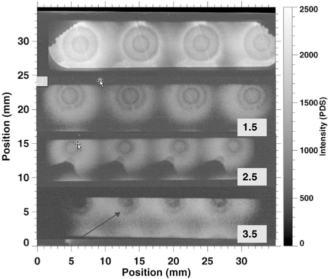
A cutout of one of the targets is shown in Figure 8, where the seam in the target is shown. The targets were radiographic at different times. Calculated radiograms of the targets were produced, and a line-out of the transmission of the He-like iron line from the backlighters were constructed (Fig. 9). The data shows structure at the edge of the shells. There are two minima in the transmissions. The outer dip in the figure occurs at the sulfur layer. The second dip occurs around the outside of the inner shell. An image of one of the implosions at 1.5 ns is shown in Figure 10. The image was collected from the detector that was positioned in the plane of the seam. The data clearly shows the seam at early and late times. The seam in the image is that line extending from 10 degrees to 170 degrees in the images. The seam persists at least until collision time. Furthermore, the seam imprint increases in time and becomes a larger fraction of the extent of the target. The effect of the seam is also noticeable in the implosion of the inner shell at later times. We also noticed that while at early times, the outer shell is imploding symmetrically, thus validating our irradiance calculations, there is an asymmetry in the implosion of the inner shell at late times. Within the very limited data at late times, the rebounding outer shell may have acquired some asymmetry.

(a) Capsule detail. The top figure shows the outside shell with the details of the joint. The CH plastic coating was used on some targets but did not have a measurable effect. (b) Capsule detail showing the inner capsule construction..
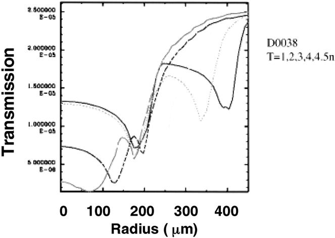
Post-processed transmission of the helium like iron line at different times.
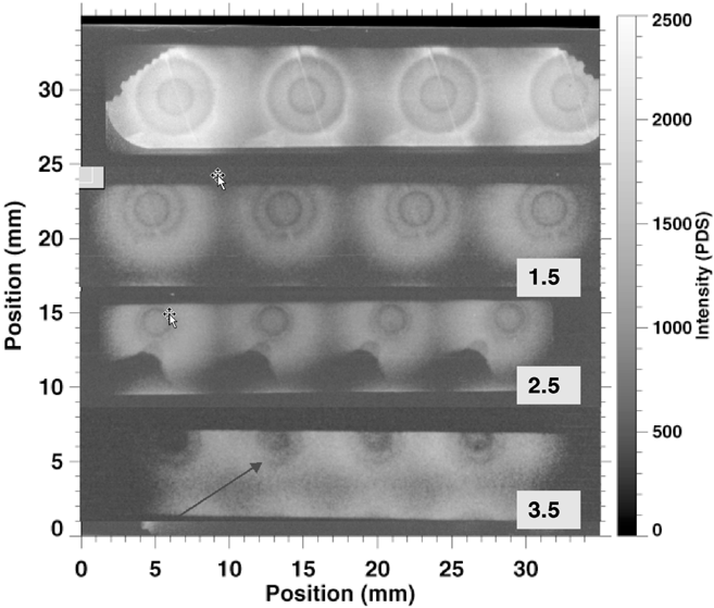
Composite of the measurements at different times. The m atμposition is measured in the film plane. The outer shell diameter is 920 zero time.
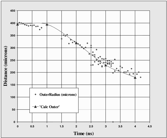
The measured history of the dip in the transmission is shown in the graph in Figure 11. The data is compared to the few calculated points that are joined by a continuous line for ease of visualization. The data agrees with the calculation for these features, and thus validate the calculations for the implosion hydrodynamics of the outer shell. Unfortunately, we did not see, with the present setup, a significant effect on the gold M-band of the expansion of the inner shell. In future experiments we will try to enhance the contrast in the inner shell.
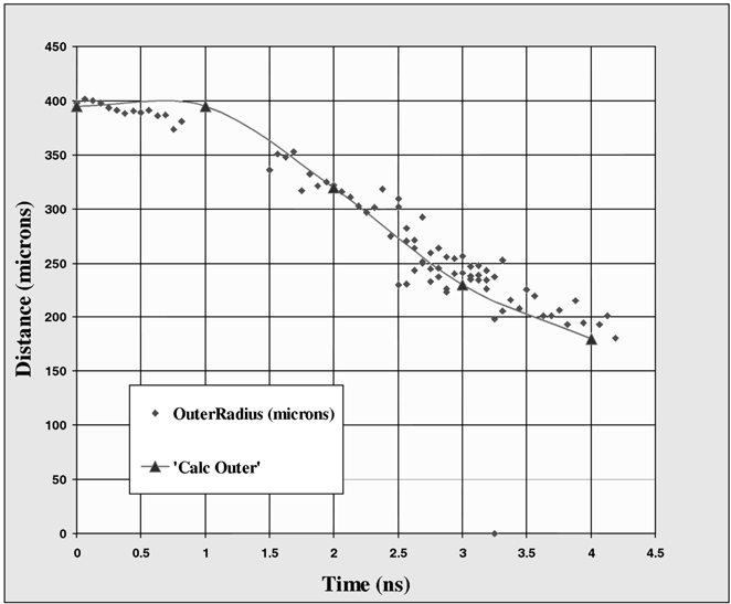
The time history of the sulfur doped layer. This is the trajectory of the dip in the transmission, compared with the measurement from the post-processed transmission calculation. A continuous line through the calculation is to guide the eye only.
The present measurements shed more light on double shell implosions. They show that although the double shells implosion capsules may approach in many cases the 1D calculations without any assumed mix, however their neutron yield is very low for the present low energy used. We also show that the behavior of the capsules depend on the amount of M-band radiation that is absorbed in the inner capsule, and those, that do not absorb enough radiation do not perform well relative to the 1D calculations. We also showed that the target construction plays a significant role in the performance, but that the calculations agree well with the implosion hydrodynamics of the outer shell.
We would like to acknowledge the helpful comment of Gail Glendinning at the Lawrence Livermore National Laboratory (LLNL), the target fabrication team at LLNL that have been attempting to build for us these difficult targets, and the Operations team in P-24 that helped execute the experiment and digitize the data, as well as the OMEGA operations crew for helping in laser pointing and the operation of some of the diagnostics. This work was performed under the auspices of the U.S. Department of Energy by Los Alamos National Laboratory under Contract No. W-7405-Eng-36.

A schematic diagram of the “standard” capsule.

A summary of the different yields for indirect drive capsule. The black open data points are from Kilkenny et al. (1988), the colored data are the more recent results at omega (Delamater et al., 2001; Varnum et al., 2000).

Diagrams of the two types of direct drive capsules used to vary the M-Band radiation on the inner capsule.

The measured ratio of the neutron yield to the 1D unmixed pre-shot calculations. Res refers to that target with resorcinol foam.

The measured yield of fusion neutrons. Res refers to that target with resorcinol.

Diagram of the Offset Pointing technique.

Layout of the experiment.

(a) Capsule detail. The top figure shows the outside shell with the details of the joint. The CH plastic coating was used on some targets but did not have a measurable effect. (b) Capsule detail showing the inner capsule construction..
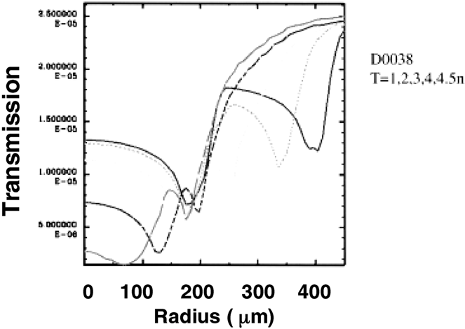
Post-processed transmission of the helium like iron line at different times.
Composite of the measurements at different times. The m atμposition is measured in the film plane. The outer shell diameter is 920 zero time.
The time history of the sulfur doped layer. This is the trajectory of the dip in the transmission, compared with the measurement from the post-processed transmission calculation. A continuous line through the calculation is to guide the eye only.