


Introduction
Substrate integrated waveguide (SIW) has attracted significant research interests in the field of microwave circuits due to its promising advantages such as high Q-factor, low profile, low loss, low cost, and high-power handling capability [Reference Deslandes and Wu1]. It has been successfully used in the high-performance bandpass filter (BPF) designs in the past few years [Reference Szydlowski, Leszczynska, Lamecki and Mrozowski2–Reference Liu, Zhou, Zhang, Zhang and Lv6]. However, those SIW cavity BPFs suffer from the existence of unwanted spurious responses in the upper stopband due to the higher-order resonant modes, which may degrade the filter performance in rejecting the undesired interference or noise. To solve this problem, numerous approaches have been proposed in recent years to realize wide stopband SIW filters [Reference Yun, Nam, Kim, Lee, Choi, Kim, Ha and Lee7–Reference Chu, Guo, Zhang, Xu, Hong and Wu22].
Among those methods, one simple way is to cascade the SIW BPF with a low-pass filter or a Defected Ground Structure (DGS) which behaves as a band-stop filter [Reference Yun, Nam, Kim, Lee, Choi, Kim, Ha and Lee7, Reference Kurudere and Ertürk8]. However, those additional structures may contribute to a larger circuit size and a higher insertion loss. On the other hand, SIW resonators with the slot on the metal surface have the ability to suppress the higher-order resonant modes [Reference Salehi and Mehrshahi9–Reference Shen, Sun, Yin, Mao and Wei11]. With properly designed slots, only the higher-order modes energy radiates while the fundamental resonant mode keeps its quality factor nearly unchanged. Another solution for the wide stopband SIW BPF design is to employ modified SIW resonators with higher spurious frequencies [Reference Huang and Chen12, Reference Moro, Moscato, Bozzi and Perregrini13]. In [Reference Huang and Chen12], inspired by the stepped impedance resonator, non-uniformly folded SIW resonators were proposed. By controlling the impedance ratio (0.33) and the length of the resonator, the first harmonic resonance frequency was pushed to a higher frequency (2.05f 0). The filter also has the merit of compact size due to the multilayer structure. In [Reference Moro, Moscato, Bozzi and Perregrini13], a modified substrate integrated folded waveguide was proposed. The excitation of the third and fourth resonant modes was prevented. The upper stopband has achieved a rejection level of 45 dB up to 2.2f 0. Recently, many efforts have been devoted to the design of the coupling structure to eliminate the higher spurious modes [Reference Shen14–Reference Jia, Feng, Xiang and Wu20]. In [Reference Lee, Lee, Lee, Uhm and Lee15, Reference Zhu, Hong, Chen and Wu17], the orthogonally feeding/coupling structure for an SIW cavity can generate transmission zeros to suppress the first two higher spurious modes (TE102 and TE201 mode). The first spurious response appears at about 2f 0 which is related to TE202 mode. In [Reference Azad and Mohan18], a short-circuited coplanar line was introduced to realize electric coupling. If the electric and magnetic couplings cancel each other for the TE102 mode, the coupling of this mode can be eliminated. A similar method has also been used in [Reference Jia, Feng, Xiang and Wu20] where the vertical coupling structure was adopted to generate electric and magnetic coupling between adjacent resonators. However, TE202 mode and other higher modes still exist. In [Reference Chu, Guo, Zhang, Xu and Wu21], in-line ports with offset from the center were proposed to suppress the TE102 and TE201 mode. The authors also developed orthogonal port with offset in the wide stopband filter design [Reference Chu, Guo, Zhang, Xu, Hong and Wu22]. The introduction of the port's offset is an improvement of [Reference Zhu, Hong, Chen and Wu17].
In our previous study, a multilayer SIW filter with wide stopband was proposed by rotating the ports and coupling slots [Reference Cheng, Li, Lu and Huang23]. However, the ports are located at different layers which may be an inconvenience in practical use. To overcome this disadvantage, coupling through the horizontal aperture is introduced in this study. Thus, both the ports can be placed at the top layer. The characteristics of the rectangular cavity resonator are analyzed. It is found that a square cavity is more suitable for the wide stopband filter design due to the fact that it has less higher-order modes than a rectangular one. Then, the method to suppress the couplings between the higher harmonics are discussed and proved by the extracted coupling coefficients. Unlike the design in [Reference Jia, Feng, Xiang and Wu20] that employs both electric and magnetic coupling, our design method is simpler because only the magnetic coupling is used. Moreover, not only the coupling between TE102/TE201 mode, but also the coupling between other higher modes are suppressed in this work. To verify the design concept, a fourth-order square cavity resonator SIW filter is achieved to work at 8.02 GHz with a wide stopband up to 2.73f 0. The proposed filter also shows the merit of a compact size because the multilayer structure is adopted.
Characteristics of the rectangular SIW cavity resonator
Figure 1 depicts the simplified structure of a dielectric-filled rectangular cavity resonator where w, l, and h are the width length, and height of the cavity, ɛr and μr are relative permittivity and relative permeability of the substrate, respectively. For such a cavity resonator, the height of the cavity is much smaller than the working wavelength. Thus, only TEm0q mode can be excited. The resonant frequencies of the TEm0q mode in the cavity are determined by [Reference Pozar24]

where c is the light velocity in vacuum, m and q are mode indices in the x- and z-axis directions, respectively. The fundamental resonant mode in a rectangular SIW cavity is TE101 mode. The frequency ratio of higher-order resonant mode to the fundamental one is given by


Fig. 1. Structure of a rectangular cavity resonator.
In equation (2), let m = q, we can get

It indicates that if a square cavity resonator and a rectangular one have the same fundamental frequency f TE101, they would also have the same higher resonant mode frequencies for TE202 and TE303 mode. Figure 2 shows the normalized frequency distribution for a square cavity resonator and a rectangular one. The highest resonant mode in Fig. 2 is chosen to be TE303 mode whose resonant frequency is three times the fundamental one. It is due to the fact that the upper stopband of the wide stopband SIW filters in the former literatures is limited to 3f 0. For a square cavity resonator (w/l = 1), it has 11 resonant modes in Fig. 2. Except for TE101, TE202, and TE303 mode, there are four couples of degenerate modes. The degenerate modes have the same resonant frequencies. For the rectangular cavity resonator (w/l = 2), each couple of degenerate modes in the square one splits into two different frequencies. So the rectangular cavity resonator has more unwanted higher mode resonant frequencies than the square one. Furthermore, a square cavity has a smaller cavity size and higher quality factor than the rectangular cavity with the same fundamental resonant frequency. Thus, the square cavity resonator is more suitable for the wide stopband filter design.

Fig. 2. Normalized frequency distribution for a square cavity resonator (w/l = 1) and a rectangular one (w/l = 2).
Analysis of the coupling structure
Magnetic field distribution of the square cavity resonator
All the resonators in our filter design are magnetically coupled. So the magnetic field distribution of the square cavity resonator is firstly analyzed. Figure 3 shows the magnetic field distribution and resonant frequencies of the first 11 resonant modes of a square cavity resonator. Rectangle A represents the input/output coupling slot. The nodes of the standing wave for TE201, TE202, TE203, and TE401 modes appear at the center of rectangle A. On each side of the node, the magnetic fields for those modes have the same amplitude and are 180° out-of-phase. Thus, none of those modes could be excited. In addition, there are two nodes of standing wave for TE301, TE302, and TE303 modes at the location of rectangle A. The coupling to those modes depends on the length of rectangle A. If rectangle A has an appropriate length, the magnetic fields would have the same amplitude and are 180° out-of-phase on each side of the node. Those modes would be weakly coupled to the input/output port. Rectangle B represents the coupling slot on the common metal layer of two vertical adjacent square cavity resonators. It is perpendicular to the magnetic field lines of TE102, TE202, TE103, TE203, and TE104 modes. So the couplings among those modes are suppressed. Meanwhile, this slot is parallel to the magnetic field lines of the other modes. As a result, the couplings of those modes are stronger. Rectangle C is the location of the post-wall iris. Its center is at the nodes of the standing wave of TE102, TE202, TE302, and TE104 modes. The couplings of those modes are suppressed. Similar to the situation of rectangle A, the couplings between TE103, TE203, and TE303 modes depends on the length of rectangle A. Those modes may be weakly coupled if a proper length is achieved. By combing those external and internal coupling structures in the filter design, the couplings of the higher resonant modes in the cavity are suppressed. Only TE101 mode can be effectively coupled.

Fig. 3. Magnetic field distribution of the first 11 resonant modes in a square cavity resonator.
Input/output coupling
The feeding structure at port 1 in Fig. 4 is employed in our filter design. At port 1, the microstrip feeding line is magnetically coupled to the cavity resonator through the slot. Port 2 is weakly coupled for extracting the external Q for the feeding structure. This model is simulated by the commercial software ANSYS HFSS 15. With the simulated transmission response, the external Q can be calculated by [Reference Hong and Lancaster25]

where f 0 is the center frequency of the transmission response, Δf 3dB is the 3 dB bandwidth of the passband. By changing the length of the slot ls, we can get the design curves for external Q as shown in Fig. 5. Figure 6 shows the wide-band transmission response of the feeding structure and the magnetic field distribution at resonant frequencies. As shown, only TE101, TE102, TE103, TE302, TE104, and TE303 modes are excited. Because the resonant frequencies of TE104 and TE303 modes are very close to each other while the coupling for TE303 mode is stronger than TE104 mode, it is difficult to see the peak for the TE104 mode. The resonant frequency of TE104 mode is estimated by the TE303 mode. In Fig. 6, f TE303 = 25.11 GHz while the frequency ratio of f TE303 and f TE104 is 1.029. So we can get f TE104 = 24.4 GHz.

Fig. 4. Structure for extracting Qe of different modes.

Fig. 5. Extracted Qe against the length of the coupling slot.

Fig. 6. Transmission response of the two-port coupled single cavity resonator and the magnetic field distribution at resonant frequencies (ls = 3 mm).
Coupling through slots
The vertically adjacent resonators are coupled through the slot on the common metal layer as shown in Fig. 7. The distance between the slot and the side is about one-fourth of the side length. The Eigen-mode simulation in HFSS is used to extract the coupling coefficients. The coupling coefficient is calculated by [Reference Hong and Lancaster25]

where f 01 and f 02 are the resonant frequencies of the corresponding modes. Figures 8(a) and 8(b) show the extracted coupling coefficients versus the slot length l 3 for weakly and strongly coupled modes, respectively. It can be found that the coupling coefficients are smaller than 0.008 for the weakly coupled modes no matter how large l 3 is. Those weakly coupled modes agree well with the former analysis. In Fig. 8(b), when l 3 changes from 1 to 8 mm, the coupling coefficient for TE101 mode has a wide range from 0.001 to 0.05 which may cover a wide range of the filter's corresponding bandwidth. In Fig. 8(a), the curves do not show the exponential feature as the curves in Fig. 8(b). The effect of weak electric coupling cannot be neglected when the magnetic coupling is also very weak. They would cancel each other. When the length of the slot increases, the increment of the electric and magnetic coupling is quite different. Thus, the curves in Fig. 8(a) have different shapes compared with those curves in Fig. 8(b).

Fig. 7. Resonators coupled through slots for extracting the coupling coefficients of different modes.

Fig. 8. Extracted coupling coefficients against the length of the coupling slot, (a) weakly coupled modes, (b) strongly coupled modes.
Coupling through the horizontal aperture
The coupling between two horizontally adjacent resonators is realized by the post-wall formed aperture as shown in Fig. 9. The extracted coupling coefficients versus the aperture width d 2 for weakly and strongly coupled modes are shown in Figs 10(a) and 10(b), respectively. The coupling coefficients for TE102, TE202, TE302, and TE104 modes are smaller than 0.014 which are much lower than those of the strongly coupled modes. It agrees well with the prediction. In addition, TE103 and TE303 modes are also weakly coupled modes whose coupling coefficients are smaller than 0.008. Although TE203 mode is categorized to be strongly coupled mode, it is the smallest one in this category while the coupling coefficients for other strongly coupled modes are all larger than 0.02. The coupling coefficient for TE101 mode ranges from 0.022 to 0.054 which may expand by further removing some vias for a wider filter bandwidth or reduce by adding more vias for a narrower filter bandwidth.

Fig. 9. Resonators coupled through the horizontal aperture for extracting the coupling coefficients of different modes.

Fig. 10. Extracted coupling coefficients against the width of the post-wall iris, (a) weakly coupled modes, (b) strongly coupled modes.
Design and measurement of the proposed filter
Figure 11 shows the final configuration of the proposed multilayer SIW filter. It consists of four square SIW cavity resonators. Resonators 1 and 2, as well as resonators 3 and 4 are vertically coupled through the rectangular slots in the middle metal layer. Resonators 2 and 3 are horizontally coupled according to the magnetic post-wall iris. This filter is designed to operate at the center frequency of 8 GHz with a relative bandwidth of 6%. The Chebyshev low-pass prototype with 0.0436 dB ripple is chosen here. The coupling matrix and external Q which satisfy those specifications can be calculated by equations (3.26) and (5.24) in [Reference Hong and Lancaster25]


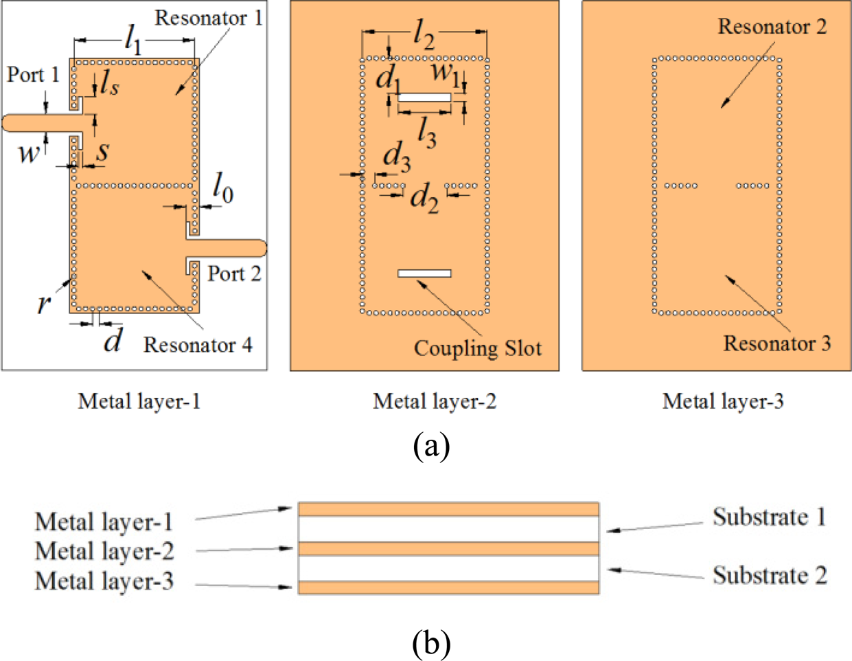
Fig. 11. Structure of the proposed multilayer SIW filter, (a) layout of each metal layer, (b) side view of the filter (l 0 = 1.7, l 1 = 15.6, l 2 = 16.16, l 3 = 6.84, ls = 2.26, w = 2.3, w 1 = 1, s = 0.5, d = 0.9, d 1 = 4.6, d 2 = 5.7, d 3 = 1.63, r = 0.3, unit: mm).
For convenience, the unnormalized coupling coefficient instead of the normalized coupling coefficients is used here because the unnormalized coupling coefficient can be read directly in the figures. The general guidelines for designing the proposed filter are as follows:
(1) The F4B substrate (dielectric constant = 2.6, loss tangent = 0.001, substrate thickness = 0.8 mm, copper thickness = 0.018 mm) is chosen for the filter design. The initial dimensions of the square SIW cavity resonator can be decided by the center frequency of the filter according to equation (1). We can get the side length of the resonator which is 16.4 mm. The accurate dimensions can be obtained by the full-wave EM simulator HFSS.
(2) According to the required external Q of the filter (Qe = 20.02), the length of the coupling slot ls is about 2.5 mm in Fig. 5. Similarly, the required coupling coefficient M 12 = 0.0425 and M 23 = 0.0326, it can be found in Figs 8(b) and 10(b) that the slot length l 3 is about 7.5 mm and the width of the post-wall iris d 2 is about 5.75 mm, respectively.
(3) Because the introduction of coupling structure and the vias which forms the metal wall would change the resonant frequencies of the resonators and coupling, all the design parameters are tuned to satisfy the filter's specifications.
The final dimensions for the SIW filter after tuning is listed in the caption of Fig. 11. Figure 12 shows the photographs of the fabricated filter. The upper and lower substrates are stacked together by screws. The overall size of the filter is 17.36 mm × 34.12 mm × 1.672 mm. Figure 13(a) shows the narrowband response of the filter. The simulated results show an insertion loss of 2.01 dB at the center frequency 8 GHz and a relative bandwidth of 6%. The measured insertion loss is 2.49 dB at the center frequency 8.02 GHz and the measured relative bandwidth is 6.23%. The measured return loss is better than 12 dB in the whole passband. Figure 13(b) is the simulated and measured wideband response of the filter. As shown, the rejection level of the measured spurious response is better than 20 dB up to 21.92 GHz which is 2.73 times the filter's center frequency. Table 1 compares our design with other reported wide stopband SIW filters. It can be seen that the designs in [Reference Moro, Moscato, Bozzi and Perregrini13, Reference Zhu, Hong, Chen and Wu17, Reference Chu, Guo, Zhang, Xu, Hong and Wu22] have deep stopband suppression better than 45 dB with a suppression bandwidth around 2f 0. If a compact size is required, the method in [Reference Moro, Moscato, Bozzi and Perregrini13, Reference Shen14, Reference Cheng, Li, Lu and Huang23] is a good choice. Our design has a wider relative bandwidth than most other designs. A wider bandwidth may lead to a stronger coupling of the higher harmonics. But our design shows a wider stopband than most other designs. Compared with [Reference Chu, Guo, Zhang, Xu, Hong and Wu22] whose ports are at different layers, our design has both ports at the same layer which is more convenient for practical use. Moreover, taking advantage of the multilayer technology, the fabricated filter has a smaller size than most other designs.

Fig. 12. Photograph of the fabricated filter, (a) before assembled, (b) after assembled.

Fig. 13. Synthesized, simulated and measured results of the proposed filters (dash dot line: synthesis, dash line: simulation, solid line: measurement), (a) narrowband response, (b) wideband response.
Table 1. Comparison of presented wide stopband SIW filter with other similar designs

Rej. (dB)/S.B.: rejection (dB)/stopband.
Conclusion
In this paper, wide stopband multilayer SIW BPF using square cavity resonators has been proposed. By properly designing the coupling structure, the couplings between the higher-order modes are suppressed. The multilayer SIW structure is effective to reduce the size of the filter by half. The proposed SIW filter shows the merits of good out-of-band rejection and compact structure size which is attractive in a modern communication system or radar system for suppressing the undesired interference in the upper stopband.
Acknowledgements
This work was supported in part by the National Natural Science Foundation of China (Grant No. 61801317) and in part by Sichuan University Postdoctoral Interdisciplinary Innovation Start-up fund project.
 Cong Tang was born in Shangqiu, Henan Province, China. He received the B.S. degree in electronic engineering from PLA Information Engineering University, Zhengzhou, China in 2010, and the Ph.D. degree at the UESTC (University of Electronic Science and Technology of China), Chengdu, China in 2018. From 2020, he joined Southwest China Institute of Electronic Technology. His research interests include millimeter-wave and microwave devices, circuits, and systems.
 Fei Cheng received the B.S. degree from Xidian University, Xi'an, China, in 2009, and the Ph.D. degree from the University of Electronics Science and Technology of China, Chengdu, China, in 2015. From 2013 to 2015, he was a visiting Ph.D. student at the University of Birmingham, UK. From 2015 to 2017, he was with Chengdu Jiuzou Dfine Technology Co. Ltd. as a microwave engineer. Since July 2017, he joined Sichuan University as an assistant professor. His main research interests are microwave components such as filter, antenna, and rectifier.
 Chao Gu received the B.S. and M.S. degrees from Xidian University, Xi'an, China, in 2009 and 2012, respectively, and the Ph.D. degree from the University of Kent, Canterbury, UK, in 2017. He is currently with the Centre for Wireless Innovation, ECIT Institute, School of Electronics, Electrical Engineering and Computer Science, Queen's University Belfast, Belfast, UK. His research interests include phased array antennas, reconfigurable antennas, and frequency-selective surfaces.


