


Introduction
Fabry–Perot cavity (FPC) antenna has been intensively investigated due to its merits of high gain, simple structure, and low profile. It usually consists of a patch antenna acting as the radiating source, a ground plane, and a metallic or dielectric superstrate [Reference Trentini1–Reference Nguyen-Trong, Tran, Nguyen and Abbosh5]. The superstrate is generally a periodic structure with uniform or non-uniform unit cells. Since these unit cells have the capability of partially reflecting energy, the superstrate is referred as a partially reflective surface (PRS). The electromagnetic waves radiating from the source antenna experience multiple reflections and transmissions between the superstrate and the ground plane. According to the ray theory, when the transmitted rays are all in phase, the radiated electric field can be enhanced, thus increasing its directivity [Reference Trentini1]. Recently, the beam-steering capability is required in many applications, such as cellular base stations, remote sensing, satellite communications, and cognitive radio [Reference Qin, Guo and Ding6–Reference Yao, Zhang and Zhang8]. Conventional FPC antennas can scan their beam with frequency, of which is the intrinsic property of leaky-wave antennas. Unfortunately, they are not suitable in many wireless communication applications which need a stable beam-steering performance to operate over a fixed frequency. Recently, many efforts have been made to design new FPC antennas that can offer beam scanning at a fixed operating frequency [Reference Ghasemi, Burokur, Dhouibi and Lustrac9, Reference Ratni, Merzouk, Lustrac, Villers, Piau and Burokur10]. The design in [Reference Ghasemi, Burokur, Dhouibi and Lustrac9] utilizes a phase-varying metasurface to control the reflection phase and thus the pointing angle at 9.5 GHz. In [Reference Ratni, Merzouk, Lustrac, Villers, Piau and Burokur10], the beam of the proposed antenna can scan up to 40° by varying the PRS inductance of the designed phase-modulated metasurfaces. The beam-steering capability of the antenna in [Reference Afzal and Esselle11] is achieved by rotating a pair of passive metasurfaces to transform the phase of the antenna near field. The beam steering of this antenna can cover a conical region having an apex angle of ±51°. Though the beam steering ranges are satisfactory, their beams cannot achieve electronic tunability. Only by changing their dimensions or by mechanically rotating the metasurface, another beam steering angle can be realized, which will limit their usages in many applications.
To realize electronic beam steering for FPC antenna, non-uniformity that can generate variable phase distributions is needed to be introduced on the superstrate, which in turn steers the radiated beam. The proposed FPC antenna in [Reference Ourir, Burokur and Lustrac12] can achieve a ±7° electronic beam steering by tuning the biasing voltages of 144 varactor diodes on the superstrate. Different biasing voltages can generate different capacitances between the diodes, leading to a phase inconsistency across different sections of the superstrate. Therefore, its beam can be tilted. By tuning the states of the reconfigurable unit cells employed on the ground, the beam of the leaky-wave antenna in [Reference Guzman-Quiros, Gomez-Tornero, Weily and Guo13, Reference Guzman-Quiros, Gomez-Tornero, Weily and Guo14] can continuously be steered in a forward direction in the range from 9 to 30° at a fixed frequency of 5.6 GHz. In [Reference Guzman-Quiros, Weily, Gomez-Tornero and Guo15], a 2D beam-steering FPC antenna is proposed using a similar structure. By independently controlling the varactors on the unit cells, this design can work on three scanning modes and generate a pencil beam at eight azimuthal directions. However, the impedance matching for the nine states is not all good. Most of the measured reflection coefficients are above −10 dB. In [Reference Ji, Guo, Qin, Gong and Mittra16], our group presents a beam-steering PRS antenna by employing reconfigurable unit cells on the superstrate in combination with a phased array source. The superstrate is divided into two parts with 72 PIN diodes employed on. By switching the states of the PIN diodes on the two parts, a ±5° beam-steering angle can be achieved by using the superstrate only. Generally, the beam-scanning property of the conventional FPC antenna is analyzed by the calculation of leakage rate α and phase constant β. Our previously reported antennas have explored a new way for FPC antennas to analyze and realize electronic beam steering based on the phased array theory; however, the beam-steering angle is still limited for most of the applications [Reference Ji, Guo, Qin, Gong and Mittra16].
This paper proposes an electronic 1D beam-steering FPC antenna with enhanced radiation performance in three discrete directions. A new reconfigurable superstrate is designed to realize beam steering. It is divided into two equal sections and each section has 3 × 6 identical reconfigurable unit cells. The unit cell consists of a rotated H-shaped metal patch in the center with one PIN diode inserted, and a pair of small coupled rectangular patches on both sides of the H-shaped patch. By turning the states of the PIN diodes on and off, the transmission phase of the unit cell on different sections can be changed to produce a phase inconsistency. The analysis method used is different from the conventional reconfigurable FPC antennas that need to calculate the phase constant of the operating mode for achieving a beam steering at a fixed frequency band. The analysis of the proposed antenna is based on the phased array antenna. The two sections can be seen as two elements of a phased array [Reference Ji, Guo, Qin, Gong and Mittra16]. According to the phased array theory, when there is a phase difference between the two sections, the beam will be tilted toward the section with a lagging phase. In this work, the proposed reconfigurable unit cell can generate a 48.6° phase difference, which can help the beam-steering angle enhanced from ±5° (our previous work in [Reference Ji, Guo, Qin, Gong and Mittra16]) to ±17°. Moreover, this design only utilizes 36 PIN diodes, half of the number of the active elements in [Reference Ji, Guo, Qin, Gong and Mittra16] and even one fourth of those in [Reference Ourir, Burokur and Lustrac12]. The maximum realized gains for all working states are over 11 dBi and the measured gain variation for all states is only 0.2 dBi.
Antenna design
Figure 1(a) plots the schematic representation of the proposed reconfigurable unit cell. It is printed on a 20 mm × 20 mm FR4 substrate and is comprised of a rotated H-shaped patch with two symmetric rectangular patches distributed on both sides. One PIN diode is inserted in the center of the H-shaped patch. The dimensions of the unit cell are listed below: the unit period P = 20 mm, the length of H-shaped patch l 1 = 18 mm, the width of H-shaped patch g 1 = 1.5 mm, g 2 = 3 mm, the length of rectangular patches l 2 = 10 mm, the width of rectangular patches w 2 = 8 mm.

Fig. 1. Schematic representation of the proposed unit cell and its simulated results of reflection/transmission coefficients.
The performance of the PRS cell has been calculated in a two-port waveguide environment by using a periodic boundary condition. PIN diodes of BAR64-02V [17] are used in this unit cell. The diode is modeled as a 2.1 Ω resistor for ON-state, and a parallel circuit which is comprised of a 0.17 pF capacitor and a 3 kΩ resistor for OFF-state.
According to ray theory in [Reference Trentini1], the realized gain of FPC antenna is determined by the reflection magnitude (|S 11|) of the PRS cell. Moreover, the beam-steering angle is dependent on the transmission phase difference (φ 21) of the PRS cell between two states on the basis of phased array theory (|S 11| and φ 21 can be obtained from the unit-cell simulation). Thus, the beam-steering angle becomes larger when the unit has a larger transmission phase difference. Figure 1(b) shows the reflection magnitudes and the transmission phases of the proposed unit cell. It is seen that the phase difference between OFF and ON states is 48.6° at 5.5 GHz. The reflection magnitudes of the proposed unit cell for OFF and ON states are −6.5 and −8.3 dB, respectively. The reflection difference between OFF and ON states is only 1.8 dB, which will result in a small gain variation.
To illustrate the advantages of the proposed unit cell, our previously designed unit cell in [Reference Ji, Guo, Qin, Gong and Mittra16] is also given as a reference in Fig. 2(a). It is a patch-type unit cell with a square microstrip patch located in the center. A slot is inserted in the middle of the patch for incorporating two PIN diodes at the edge. When the PIN diodes are switched OFF, the two halves of the patch disconnect from each other, which results in a surface with a high reflectivity and a small transmission phase. When the PIN diodes are switched ON, a larger phase value is obtained compared with that of OFF-state (see Fig. 2(b)). The phase difference caused by the PIN diodes between two states is 27.5° at the operating frequency of 5.5 GHz, which is about 20° smaller than that of the proposed unit cell. Moreover, the reflection magnitudes for OFF and ON states are −1.8 and −6.6 dB, respectively. The reflection difference is 4.8 dB as opposed to 1.8 dB of the proposed unit cell. Therefore, its beam-steering range will be smaller than the proposed antenna with a much larger gain variation range. By employing 6 × 6 such patch-type cells on the superstrate, this antenna can achieve a ±5° beam scanning with a maximum gain of 14.3 dBi and a gain variation about 2.5 dBi [Reference Ji, Guo, Qin, Gong and Mittra16].

Fig. 2. (a) Schematic representation of the unit cell in [Reference Ji, Guo, Qin, Gong and Mittra16] and (b) its relevant simulated results.
As a performance comparison between the patch-type unit cell and the proposed unit cell, the designed FPC antenna in this paper also utilizes 6 × 6 unit cells. Figure 3 gives the schematic representation of the whole FPC antenna. A coaxial-fed square patch antenna of length 13.2 mm is used as a radiating element. The dimensions of the proposed antenna are 150 mm × 150 mm. Its cavity height L r is chosen as 31.5 mm, which is calculated according to the boresight radiation resonance condition of FPC antennas as follows [Reference Trentini1]
 $$L_r = \left( {\displaystyle{\varphi \over \pi} - 1} \right)\displaystyle{\lambda \over 4} + N\displaystyle{\lambda \over 2},N = 0,1,2...$$
where φ is the reflection phase of the superstrate. Its detailed reconfigurable superstrate is shown in Fig. 4. It is equally divided into two sections shown as Part I and Part II in the figure. Each section has 3 × 6 proposed unit cells. The PIN diodes on the superstrate are all oriented in the same direction. For the DC biasing, the unit cells in each column are connected in series by using a 0.2 mm thin metallic biasing striplines (marked as sky blue lines) and an 18 nH surface-mounted RF choke inductor (marked as red rectangular), thus all the six columns are connected in parallel by using the same inductive biasing lines. Two capacitors are inserted in each row between the two parts to maintain the RF connection while providing DC signal isolation.

Fig. 3. Schematic representation of the FPC antenna.

Fig. 4. The reconfigurable superstrate.
Due to the above arrangement of the unit cells, the reconfigurable superstrate has four states in total: State-1 refers to all diodes turned OFF; State-2 refers to all diodes ON; State-3 refers to Part I OFF with Part II ON; State-4 is opposite to State-3. For State-1 and State-2, there is no phase difference between these two parts, thus the proposed antenna can radiate a conventional boresight beam. For State-3, Part II (ON-state) has a 48.6° lagging phase than that of Part I (OFF-state, see results in Fig. 2(b)). Hence the beam will be tilted toward Part II (–y direction in Fig. 4). Similarly, State-4 results in a beam steered to +y direction. Since structures in Part I and Part II are identical and in parallel, only one biasing voltage is needed for this design.
Parametric discussion
In order to illustrate the effects of some key parameters on the antenna performance, a parametric study of three unit-cell dimensions, namely the length and width of the coupled rectangular patches l 2 and w 2, and the length of the H-shaped patch l 1, has been carried out to provide insights on how to design other beam-steering angles.
Figure 5(a) shows the effects of l 2 on the phase difference of the unit and beam-steering angle of the proposed FPC antenna. It is seen that the variation of the unit phase difference increases when l 2 rises to 10 mm, then goes down when l 2 rises to 12 mm. The phase difference variation range is from 33.7° (l 2 = 12 mm) to 48.6° (l 2 = 10 mm). Accordingly, the beam-steering angle is changed from 12° (with a maximum realized gain of 13.1 dBi) to the designed angle of 17° (with a maximum realized gain of 10.7 dBi).

Fig. 5. The effects of some key parameters on the antenna performance.
Figure 5(b) plots the effects of w 2. As clearly shown in this figure, the variation of w 2 has a more significant influence on the unit phase difference. When w 2 increases from 4 to 8 mm, the phase difference is monotonously enhanced from 12.8° to 48.6°. As a consequence, the beam-steering angle is gradually increased from 9° to 17°. Since the reflection coefficient of the unit cell only has a small change with the variation of w 2, the realized gain of the FPC antenna is around 10.7 dBi for all w 2 values.
The effects of l 1 are given in Fig. 5(c). When l 1 increases from 16 to 20 mm, the unit phase difference is decreased from 55° to 42.6°. The beam-steering angle has a similar trend. However, the variation range is rather small (14–17.5°). Due to the structure of the proposed unit cell, the smaller the value of l 1 is, the longer the biasing line between the two adjacent unit cells is. Redundant biasing lines will introduce more losses, leading to a reduced realized gain. In order to make a compromise between beam-steering angle and realized gain, l 1 = 18 mm, l 2 = 10 mm, and w 2 = 8 mm are chosen in this design.
The effects of the size of the superstrate and the cell number have been also investigated in this paper. We simulated the situations when 4 × 4, 6 × 6, 8 × 8, and 10 × 10 cells are employed on the superstrate and their results are given in Table 1. From this table, it is seen that when employing more unit cells on the superstrate, a higher boresight gain is generated owing to the increase of the lateral dimension. Moreover, a larger beam-steering angle can be achieved. As a consequence, 6 × 6 configuration is chosen in this paper to make a compromise between the beam-steering angle and antenna gain.
Table 1. Simulated cell number effects on the radiation performance

Antenna results
A beam-steering FPC antenna prototype has been fabricated and measured. Its photograph is given in Fig. 6. Figure 7 plots a comparison between the simulated and measured input reflection coefficients for the four states. It is seen that a good agreement is achieved. For State-1 and State-2, the 10 dB impedance bandwidth is from 5.48 to 5.65 GHz. While for State-3 and State-4, the bandwidth range is 5.44–5.65 GHz. Therefore, an overlapped impedance bandwidth from 5.48 to 5.65 GHz is achieved for all the operating states.
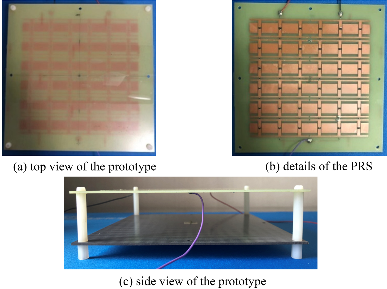
Fig. 6. Photograph of the fabricated FPC antenna. (a) Top view of the prototype; (b) details of the PRS; (c) side view of the prototype.

Fig. 7. Input reflection coefficients of the proposed antenna. (a) State-1 and State-2; (b) State-3 and State-4.
Since the gains of State-1 are much lower than the other three states, its pattern results are omitted here for brevity. The simulated and measured radiation patterns are given in Fig. 8. It is observed that in the H-plane (yoz plane), a broadside radiation is obtained at State-2 with a maximum gain of 11.3 dBi. For State-3 and State-4, the beam directions are tilted toward −17 and 17° from the broadside. The measured maximum gains are all 11 dBi. The gain variation from the broadside direction to the tilted direction is only 0.2 dBi. In the E-plane (xoz plane), the boresight gains for State-3 and State-4 are lower than State-2 as the beams are scanned off the boresight direction.

Fig. 8. Realized gain patterns of the proposed antenna. (a) H-plane at 5.4 GHz; (b) H-plane at 5.5 GHz; (c) H-plane at 5.6 GHz; (d) E-plane at 5.5 GHz.
It is well known that when the beam-steering angle is large, its realized gain will be reduced. Compared with our previous work in [Reference Ji, Guo, Qin, Gong and Mittra16] (±5° beam steering with a gain of 14.5 dBi), the realized gains in this paper are reduced since the beam-steering range becomes larger. Therefore, it is a tradeoff between high gains and beam-steering range. It depends on the application whether a high gain with small beam-steering range or a medium gain with a large beam-steering range is needed. Moreover, the gain variation of the proposed antenna is smaller than that in [Reference Ji, Guo, Qin, Gong and Mittra16] due to the reduction of the reflection difference mentioned in section “Antenna design”.
Conclusion
A novel reconfigurable FPC antenna with a wide-angle 1D beam-steering capability has been presented in this work. By controlling the states of reconfigurable unit cells on the superstrate, the proposed antenna can achieve a ±17° beam tilt with respect to the broadside direction, across an overlapped 10 dB impedance bandwidth from 5.48 to 5.65 GHz. The measured realized gains are over 11 dBi for all states with a gain variation not over 0.2 dBi. Compared with other reported beam-steering designs, the beam-steering range of the proposed FPC antenna is wider. Moreover, it has the advantages of a rather small gain variation, a simpler biasing network, and a stable beam-tilt performance.
Acknowledgements
This work was supported by the National Science Foundation of China under Grant 61701411.
 Lu-Yang Ji was born in Shaanxi Province, China, in 1989. She received the B.S. degree in electronic engineering and the Ph.D. degree in electromagnetics from Xidian University in 2010 and 2016, respectively. From 2013 to 2015, she had worked as a visiting Ph.D. student in reconfigurable antennas at CSIRO DPAS Flagship, Marsfield, Australia. She now works as an assistant professor at Northwestern Polytechnical University. Her research interests are in the areas of reconfigurable antennas and wideband antennas.
 Shuai Fu received his B.S. degree in electronic engineering and the M.S degree in optical engineering from Xidian University in 2010 and 2014, respectively. He now works as an engineer at Northwest Regional Air Traffic Management Bureau of CAAC. His research interests are in the areas of meteorological radars and phased array antennas.
 Lin-Xi Zhang received his B.S. degree in electronic engineering in 1986 from Nanjing University of Science and Technology and the M.S degree in communication and electronic system in 1991 from Beijing Institute of Technology. He was working as a deputy director in Radio Laboratory of Unmanned Aerial Vehicle Research Institute in Northwest Polytechnic University awarded. He now works as a professor at Northwestern Polytechnical University. His research interests are in the areas of RCS reduction of the unmanned systems and antenna measurements.
 Jian-Ying Li received his Ph.D. degree in electromagnetics from Xidian University in 1992. From 2001 to 2010, he was working as a research scientist at the National University of Singapore. He now works as a professor at Northwestern Polytechnical University. His research interests are in the areas of electrically small antenna, wideband antenna arrays, and conformal antenna arrays.


