1. INTRODUCTION
Ideally, a large number of globally and evenly distributed monitor stations are needed by Global Navigation Satellite Systems (GNSS) to continuously track and observe satellites for orbit determination. However, it is difficult for the BeiDou System (BDS) to construct monitoring stations globally, and all of the monitoring stations are currently located on the Chinese mainland. When Medium Earth Orbit (MEO) satellites depart from the regional monitor network, tracking and observation are interrupted, which leads to a decrease in the accuracy of satellite orbits and clocks, as well as the Positioning, Navigation and Timing (PNT) service performance of BDS (Montenbruck et al., 2012; Guo et al., Reference Guo, Hu, Tang, Huang, Liu and Cheng2010; Zhou et al., Reference Zhou, Hu and Wu2010).
BDS-3 has entered the constellation construction phase with the launch of two BDS-3 MEO satellites into orbit on 5 November 2017 and is expected to be completed by 2020. The BDS-3 constellation will consist of three Geosynchronous Orbit (GEO), three Inclined Geosynchronous Orbit (IGSO) and 24 MEO satellites. The three GEO satellites are located at 80°E, 110·5°E and 140°E, respectively, the three IGSO satellites have an inclination of 55°, and the 24 MEO satellites are evenly distributed in three orbital planes, with a Right Ascension of Ascending Node (RAAN) interval of 120° (Yang et al., Reference Yang, Xu, Li and Yang2018). With the launch of the MEO satellites, the service areas of BDS-3 will be expanded to the whole world. Then, the disadvantages of only having regional tracking and monitoring stations will become more severe.
A significant improvement of BDS-3 is the Inter-Satellite Link (ISL). The idea of an ISL was first proposed by Ananda et al. (Reference Ananda, Bemstein, Cunlllgham, Feess and Stroud1990) to implement autonomous navigation and to reduce the dependence on the ground segment of the navigation system and several simulation analyses demonstrated that ISL can also be used to improve orbit determination effectively together with regional monitoring stations (Wolf, Reference Wolf2000; Liu et al., Reference Liu, Geng and Zhao2011; Xu et al., Reference Xu, Wang and Zhan2012; Wang et al., Reference Wang, Xie and Zhuang2017). In 1997, a Global Positioning System (GPS) BLOCK IIR satellite equipped with an Ultra-High Frequency (UHF) band ISL antenna was launched. Then, an autonomous navigation experiment was successfully conducted (Fisher and Ghassemi, Reference Fisher and Ghassemi1999), which revealed that the 75-day User Range Error (URE) was better than 3 m (Rajan, Reference Rajan2002). Further study found that UHF-band ISL has a poor anti-interference capability and large measurement noise, and the observations were seriously affected by multipath effects (Rajan et al., Reference Rajan, Brodie and Rawicz2003a; Reference Rajan, Orr and Wang2003b), hence GPS III satellites are equipped with upgraded antennae, and each satellite in the constellation will have the ability to make ISL measurements and communicate with other satellites. (Maine et al., Reference Maine, Anderson and Langer2003; Luba et al., Reference Luba, Boyd, Gower and Crum2005; Wen et al., Reference Wen, Zhu, Gong, Wang and He2019). Given the successful experience of GPS, Globalnaya Navigazionnaya Sputnikovaya Sistema (GLONASS) and Galileo have also proposed their own ISL development plans (Revnivych, 2012; Kulik, Reference Kulik2001; Fernández Reference Fernández2011).
To test the key technologies of BDS-3, five experimental BDS-3 satellites (BDS-3-E) equipped with Ka-band ISL antennae have been launched since 2015, including two IGSO satellites and three MEO satellites. The results show that centralised autonomous orbit determination based on four BDS-3-E satellites and an anchor station is better than 15 cm for IGSO and 10 cm for MEO in a radial direction, respectively (Tang et al., Reference Tang, Hu, Zhou, Liu, Pan and Chen2018). When the accuracy of the prior orbit is 10 m, the position accuracy of the centralised autonomous orbit determination is better than 2 m using only ISL observations (Ren et al., Reference Ren, Yang, Zhu and Xu2017). For BDS-3-E satellites, the RMS of Overlapping Orbit Differences (OODs) for the ISL enhanced orbit determination based on regional ground stations is better than 0·1 m in the radial direction, and is better than 0·5 m in Three-Dimensional (3D) position (Chen et al., Reference Chen, Hu, Tang, Zhou, Guo and Pan2016a), and the orbit accuracy can be improved by about 37–76% (Yang et al., Reference Yang, Yang, Li, Zhou and Tang2017).
This paper will present the initial results of ISL enhanced orbit determination for eight BDS-3 MEO satellites based on ten Chinese domestic stations and 13 international GNSS Monitoring and Assessment System (iGMAS) overseas stations. The paper is organised as follows: the ISL measurement calculation is introduced in Section 2. Then, the methods and strategy of the orbit determination are described, and the characteristics of the ISL measurement are analysed in Section 3. The results of the experiment are given in Section 4. Finally, conclusions and discussion are provided in Section 5.
2. ISL MEASUREMENT CALCULATION
The BDS ISL is constructed based on a Concurrent Spatial Time Division (CSTD) system (Yang et al., Reference Yang, Yang, Li, Zhou and Tang2017). In the operation process, the ground segment of BDS generates a series of link-building commands for the mutually visible satellite pairs and injects them upward into the satellite processors. The elapsed time of each inter-satellite link is 3 s, while the former 1·5 s is for forward ranging from Satellite A to B, and the latter is for backward ranging from Satellite B to A. The ISLs can be divided into two types: in-plane links and out-of-plane links. For in-plane links, the relative position between two satellites remains unchanged, which means that one satellite is invisible to the adjacent two satellites because of the large nadir angle. Besides the invisible two satellites mentioned above, the satellite on the opposite side of the Earth is also invisible, and the remaining four satellites are continuously visible. For out-of-plane links, each satellite can link with ten different satellites, but the relative positions of the satellites are always changing, and the time span of the ISL visibility is discontinuous (Wang et al., Reference Wang, Xie and Zhuang2017).
It is assumed that Satellite B receives the ranging measurement ρAB(t1) from Satellite A at its local time t1, and Satellite A receives the ranging measurement ρBA(t2) from Satellite B at its local time t2. The two dual-one-way ranging measurements at the middle time t0 can be calculated based on the following formula:
 $$\rho _{AB} \lpar {\rm t}_0 \rpar = \rho _{AB} \lpar {\rm t}_1 \rpar +d\rho _{AB} =\vert {\vec {R}_B \lpar {\rm t}_0 \rpar -\vec {R}_A \lpar {\rm t}_0 \rpar } \vert +c\cdot \lsqb T_B \lpar {\rm t}_0 \rpar -T_A \lpar {\rm t}_0 \rpar \rsqb +c\cdot \lsqb \delta _A^{trans} +\delta_B^{rcv} \rsqb +\xi $$
 $$\rho _{BA} \lpar {\rm t}_0 \rpar = \rho _{BA} \lpar {\rm t}_2 \rpar +d\rho _{BA} =\vert {\vec {R}_B \lpar {\rm t}_0 \rpar -\vec {R}_A \lpar {\rm t}_0 \rpar } \vert +c\cdot \lsqb T_A \lpar {\rm t}_0 \rpar -T_B \lpar {\rm t}_0 \rpar \rsqb +c\cdot \lsqb \delta _B^{trans} +\delta_A^{rcv} \rsqb +\xi $$
where dρAB and dρBA are the distance corrections,  $\vec {R}_{A} $ and
  $\vec {R}_{B} $ are the cartesian coordinate vectors of Satellite A and Satellite B, T A and T B are the clock offsets, δTrans and δRcv are the transmitting and receiving hardware delays, c is the speed of light and ξ includes the satellite antenna offset, relativistic effect, ionosphere delay gravitational time delay and other unknown errors. dρAB and dρBA can be expressed as the following formula:
 $$\eqalign{d\rho _{AB} & = \vert {\vec {R}_B \lpar {\rm t}_0 \rpar -\vec {R}_A \lpar {\rm t}_0 \rpar } \vert -\vert {\vec {R}_B \lpar {\rm t}_1 \rpar -\vec {R}_A \lpar {\rm t}_1 -\Delta {\rm t}_1 \rpar } \vert +c\cdot \lsqb T_B \lpar {\rm t}_0 \rpar -T_A \lpar {\rm t}_0 \rpar \rsqb \cr & \quad -c\cdot \lsqb T_B \lpar {\rm t}_1 \rpar -T_A \lpar {\rm t}_1 -\Delta {\rm t}_1 \rpar \rsqb } $$
 $$\eqalign{d\rho _{BA} & =\vert {\vec {R}_A \lpar {\rm t}_0 \rpar -\vec {R}_B \lpar {\rm t}_0 \rpar } \vert -\vert {\vec {R}_A \lpar {\rm t}_2 \rpar -\vec {R}_B \lpar {\rm t}_2 -\Delta {\rm t}_2 \rpar } \vert +c\cdot \lsqb T_A \lpar {\rm t}_0 \rpar -T_B \lpar {\rm t}_0 \rpar \rsqb \cr & \quad -c\cdot \lsqb T_A \lpar {\rm t}_2 \rpar -T_B \lpar {\rm t}_2 -\Delta {\rm t}_2 \rpar \rsqb } $$
Though the accuracy of the a priori orbit and clock is limited, satellite velocity accuracy better than 0·1 mm/s and the satellite clock drift accuracy better than 1E-13s/s can be achieved because the difference between t0 and t1 or t2 is less than 1·5 s. Thus, the distance correction accuracy can be better than 1 cm (Tang et al., Reference Tang, Hu, Zhou, Liu, Pan and Chen2018). The addition of ρAB(t0) and ρBA(t0) is the pseudorange measurement which is free of clock offset and can be used for orbit determination. The subtraction of ρAB(t0) and ρBA(t0) is the relative clock offset which is independent of the satellite distance.
 $$\tilde {\rho }_{AB} \lpar {\rm t}_0 \rpar = \displaystyle{{\rho _{AB} \lpar {\rm t}_0 \rpar +\rho _{BA} \lpar {\rm t}_0 \rpar }\over{2}}=\vert {\vec {R}_A \lpar {\rm t}_0 \rpar -\vec {R}_B \lpar {\rm t}_0 \rpar } \vert +c\cdot \delta_{{\rm A}}^{del} +c\cdot \delta _B^{del} +\xi $$
 $$\delta \tilde {T}_{AB} \lpar {\rm t}_0 \rpar = \displaystyle{{\rho _{AB} \lpar {\rm t}_0 \rpar -\rho _{BA} \lpar {\rm t}_0 \rpar }\over{2\cdot c}}=T_B \lpar {\rm t}_0 \rpar -T_A \lpar {\rm t}_0 \rpar +\displaystyle{{1}\over{2}}\cdot \lpar \delta _A^{trans} -\delta _A^{rcv} +\delta _B^{rcv} -\delta _B^{trans} \rpar +\xi $$
where  $\delta_{{\rm A}}^{del}$ and
  $\delta _{B}^{del}$ are hardware delays of the ISL device with expressions as follows:
 $$\delta_{{\rm A}}^{del} = \displaystyle{{\delta _A^{trans} +\delta_A^{rcv}}\over{2}} $$
 $$\delta _B^{del} = \displaystyle{{\delta _B^{trans} +\delta _B^{rcv}}\over{2}} $$
Figure 1. ISL measurement calculation.
3. ISL ENHANCED ORBIT DETERMINATION EXPERIMENT
The experiment was carried out from Day Of Year (DOY) 133 to 146 of 2018 (13 to 26 May 2018), which was 14 days in total. During the experiment, there were 15 BDS-2 satellites, 13 BDS-3-E satellites and eight BDS-3 satellites in operation, of which C01, C02, C04 and C17 manoeuvred and are excluded from orbit determination. The ISL devices of the BDS-3-E satellites were under maintenance, therefore only the ISL measurements of BDS-3 satellites were considered. Few International GNSS Service (IGS) stations are equipped with receivers that can receive signals of BDS-3 satellites and many of them are single frequency. Fortunately, iGMAS has built several overseas stations, and all of them can receive BDS-3 B1I and B3I signals (Chen et al., Reference Chen, Xu, Yang, Cai and Chen2016b), which can be used for the orbit determination experiment. 23 ground stations were used in the experiment, including ten Chinese domestic stations and 13 iGMAS overseas stations (see Figure 2).
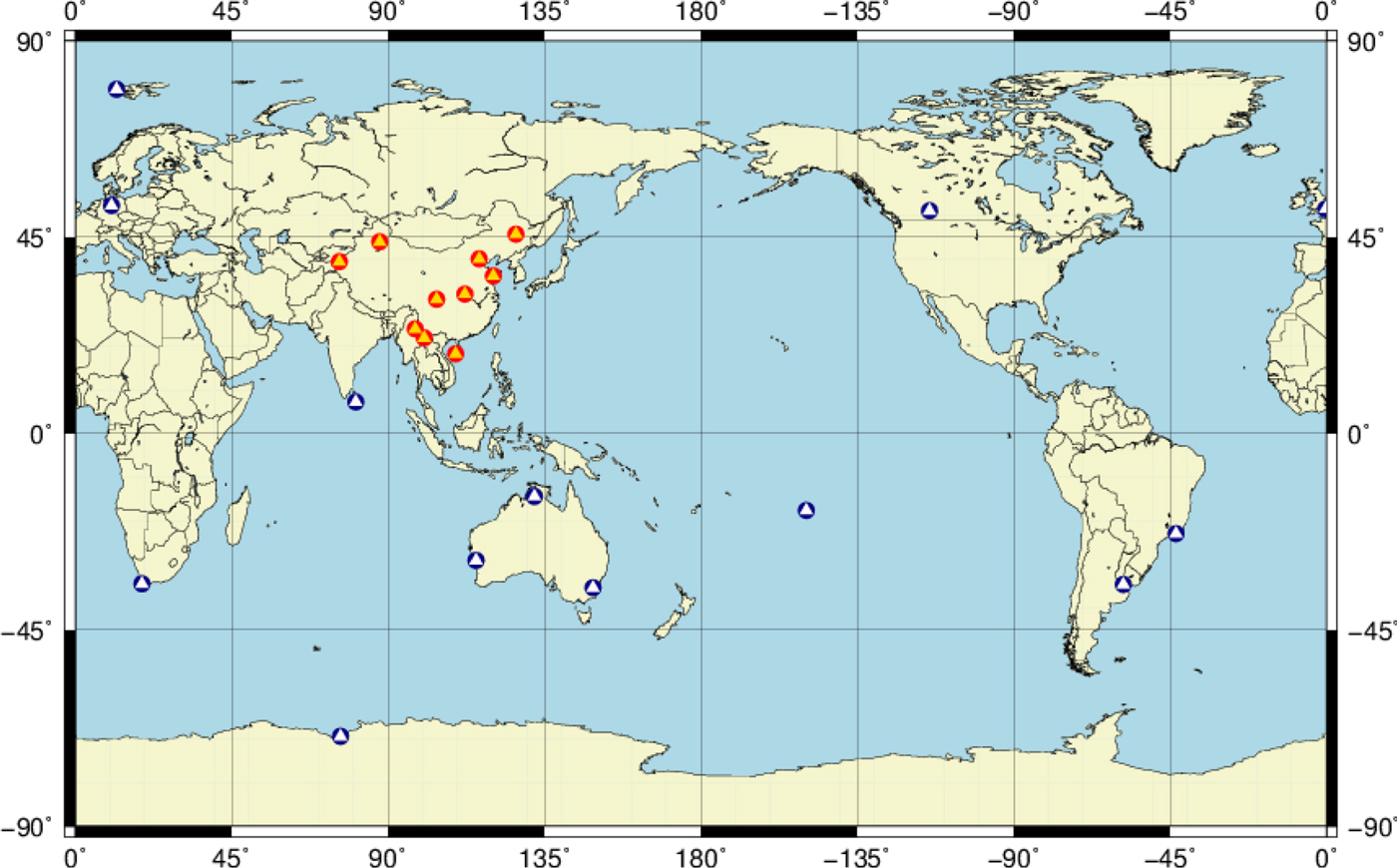
Figure 2. Chinese domestic stations (red) and iGMAS overseas stations (blue) used in the experiment.
Table 1. Orbit determination strategy.
3.1. Model and strategy of orbit determination
The experiments were divided into four schemes:
(1) Regional Stations (RS). The dynamic orbits of 22 BeiDou satellites were determined, including 11 BDS-2 satellites, three BDS-3-E satellites and eight BDS-3 satellites. The coordinates of all stations were fixed to ITRF2008.
(2) RS and ISL. The BDS-3 ISL measurement was included compared to the RS solution.
(3) Global Stations (GS). The 13 overseas iGMAS stations were included and compared to the RS solution. Considering that most iGMAS stations cannot receive the signals of BeiDou GEO and IGSO satellites, the dynamic orbits of GPS satellites were determined in order to improve the quality of the solution. One Inter-System Bias (ISB) parameter per iGMAS station was estimated. The coordinates of iGMAS stations were fixed to ITRF2008, and the coordinates of domestic stations were estimated.
(4) GS and ISL. The BDS-3 ISL measurement was included and compared to the GS solution. The GPS satellites included were the same as for the GS solution.
The orbit determination was conducted using the least squares principle with a three-day arc in the statistical orbit determination form (Tapley et al., Reference Tapley, Schutz and Born1973). The input measurements of the ground station were undifferenced ionospheric-free code and phase combination of B1I and B3I with an interval of 30 s and the measurements of ISL were Ka-band ISL measurements with an interval of 3 s. There are several differences between the calculation of ground station measurements and ISL measurements: (1) The tropospheric delays of the ground station measurements were corrected by the Saastamoinen (Reference Saastamoinen1972) model and the Global Mapping Function (GMF) function, while no correction was needed for the ISL measurements. (2) The first-order ionospheric delays of the ground measurements were eliminated by ionospheric-free combination, and the high-order effects were ignored. There were no ionosphere delays for ISLs between satellites and no correction was needed. (3) The influences of the tide were considered for the ground measurements, while the tide effect did not exist in the ISL measurements.
3.2. ISL measurement characteristics
To ensure accuracy, only two dual-one-way ranging measurements within 3 s were matched to calculate the ISL measurement according to Section 2. If only one-way ranging measurement was available, the measurement was invalid. The statuses of the ISL measurements from DOY 144 to 146 in 2018 are shown in Figure 3. The yellow points represent the forward ranging from Satellite A to Satellite B, and the red points represent the reverse ranging from Satellite B to Satellite A. In general, the relative positions of the satellites in the same plane are almost unchanged, and thus the in-plane links between them are continuous (see C28 and C29). Moreover, the relative positions of satellites in different planes vary with time and parts of the out-of-plane links are discontinuous (see C21 and C30). It should be noted that there are interruptions of ISL data for approximately 5 h every day, from 0 h to 5 h, and sometimes only one-way ranging is available. This kind of data interruption may be caused by system debugging due to communication link interruption and blocking, which shows that the ISL is currently not stable enough.
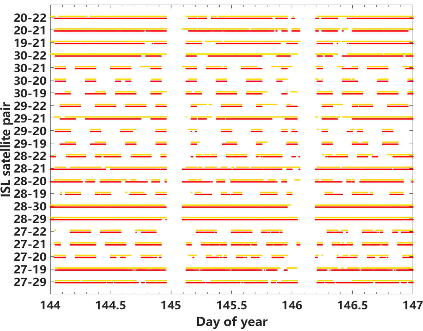
Figure 3. Status of ISLs during DOY 144 – 146, 2018.
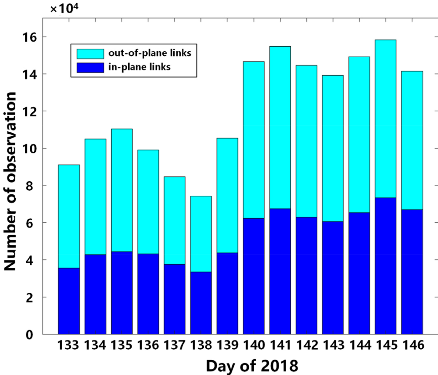
Two dual-one-way ranging measurements can form one pseudorange measurement. For the eight BDS-3 satellites, more than 150,000 ISL pseudorange measurements were formed every day. Figure 4 shows the amount of ISL pseudorange measurements during the experiment. The blue portions represent the in-plane links, and the cyan portions represent the out-of-plane links. It is clear that the out-of-plane links data are more numerous than those of in-plane links. For DOY 140, the amount of pseudorange measurement data increased from 80,000 to approximately 150,000. This is because the ISL devices of C29 and C30 have been in operation since then.

Figure 4. Number of pseudorange measurements.
According to Equation (6),  $\delta \tilde{T}_{AB} \lpar {\rm t}_{0} \rpar $ does not include satellite distance and is only affected by satellite clock offsets, equipment transmission delays, reception delays and measurement noise. The variation of the clock offset is slow, and the transmission and reception delays of the ISL device can be considered as a constant value for a several-days arc. Therefore, the clock offset detrended by the polynomial model can reflect the characteristics of the ISL measurements.
The one-hour detrended clock offset does not include the clock offset variation, hardware delay and various slow-varying errors, and can be used for the analysis of the measurement noise. The results show that the noise levels of satellites produced by the China Academy of Space Technology (CAST) and China Academy of Science (CAS) are not the same because the Ka-band antennae used by them are different. The noise for C19, C20, C21 and C22 produced by CAST is about 1 cm, and it is 3 cm for C27, C28, C29 and C30 produced by CAS. The noise RMS of out-of-plane links between satellites of different manufacturers is about 2 cm, indicating that the ISL device of BDS-3 satellites has an ideal measurement noise level.
The 24-hour detrended clock offset does not include clock offset variation and systematic errors and contains unmoulded slow-varying errors and measurement noise, which can be used to analyse the accuracy of measurements. The detrended ISL clock offsets of DOY 140 are shown in Figure 5, and the different colours represent different ISLs. It can be seen that the clock residuals contain not only measurement noise but also slow-varying errors. The different characteristics of in-plane links and out-of-plane links can also be observed in the figure. The residuals of in-plane links are about ±0·15 m because the variation of errors related to positional relationships is smaller. The residuals of out-of-plane links are about ±0·2 m, which is larger than those of the in-plane links. The RMS of the residuals is about 6 cm. As is known, the precision of the phase measurement is approximately several millimetres, and it is several decimetres for code measurement. Therefore, the weight ratio of phase, code and ISL measurements is set to 10,000:1:100.
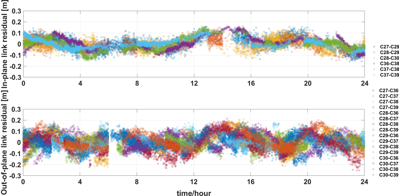
Figure 5. ISL measurement error of in-plane link (top) and out-of-plane link (bottom).
4. RESULTS AND VALIDATION
4.1. Observation residuals
The observation residuals include multipath effect, measurement noise, and the correction residuals of various model errors, which can be used to validate the internal accuracy of the determined orbit. The rejection threshold of gross error is three times sigma. The RMS results of each type of observation residuals are listed in Table 2.
Table 2. RMS of observation residuals (unit: cm).

Since the receivers of the Chinese domestic stations are the same type, the observation residuals are quite small, and the RMS is approximately 60 ~ 80 cm for code residuals, approximately 1 cm for phase residuals and 4 cm for ISL residuals. The ISL observations have little effect on the ground-based observation residuals. By adding the observations of iGMAS stations, the RMS of residuals is approximately 110 ~ 120 cm for code residuals, which is obviously larger than those of Chinese domestic stations-only solutions. This may be caused by different types of GNSS receivers fitted at different iGMAS stations.
Figure 6 shows the ISL observation residuals of the RS and ISL solution during DOY 146 and 148. The result of the GS and ISL solution is similar to that of the RS and ISL solution, which is not shown. It can be seen that the residuals of in-plane links and out-of-plane links are about ±0·2 m and are of the same magnitude. It is worth noting that a jump can be readily seen for all the residuals related to C30 around DOY 146·7, and the maximum value is close to 0·35 m. This is because the solar panel attitude of C30 had been adjusted.
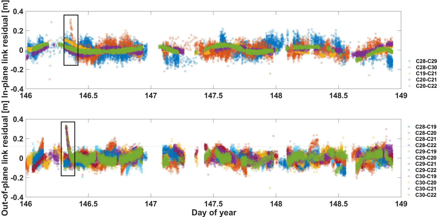
Figure 6. ISL observation residuals of in-plane link (top) and out-of-plane link (bottom).
4.2. Overlap orbit comparison
OOD is often used to evaluate the internal accuracy and stability of the orbit determination. Two-day overlap orbits can be obtained by orbit comparisons of any two groups of the three-day arc orbit solutions with a time-lag of one day to conduct the internal validation, as shown in Figure 7.

Figure 7. Overlapping comparisons.
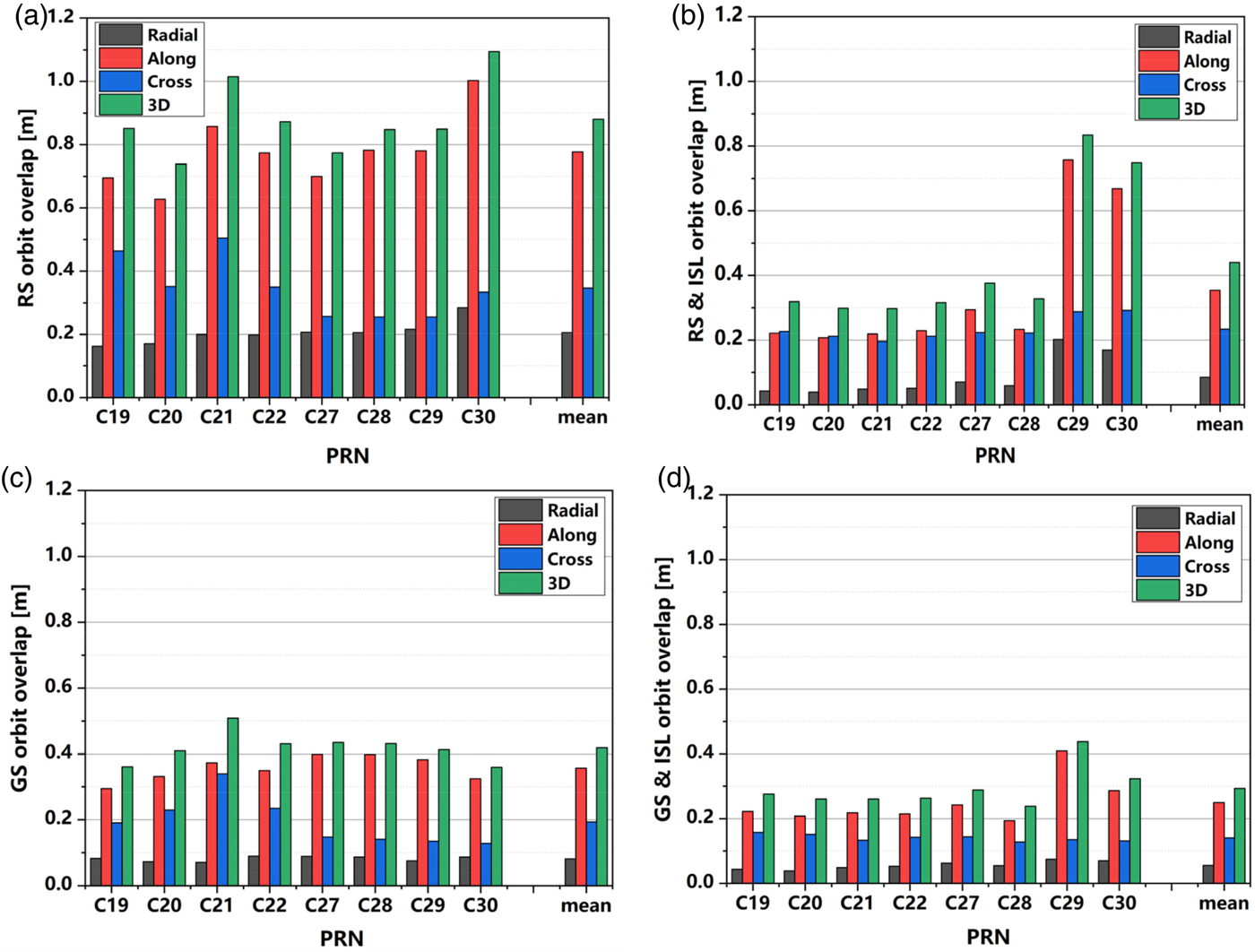
The experiment lasted 14 days, each observation arc was three days, and there were 12 arcs and 11 overlapping orbit arcs. The RMS of OODs in the Radial direction (R), Along-track direction (A), Cross-track direction (C), as well as the 3D position are listed in Table 3, and the OOD comparisons of BDS-3 satellites for the RS, RS and ISL, GS, and GS and ISL solutions are shown in Figure 8.

Figure 8. Overlap orbit comparison of BDS-3 satellites of the RS (a), RS and ISL (b), GS (c), and GS and ISL (d) solution.
Table 3. RMS of OODs (unit: m).
The results show the following:
(1) ISL observations can significantly improve the orbit accuracy of BDS-3 satellites for both the RS and GS solution. By adding ISL measurements, the 3D position RMS of BDS-3 satellites OODs for the RS solution decreased from 0·88 m to 0·44 m, which is a 50% improvement, and in the radial direction RMS decreased from 0·21 m to smaller than 0·1 m. The 3D position RMS for the GS solution decreased from 0·42 m to 0·29 m, which is a 31% improvement and the radial direction RMS decreased from 0·08 m to better than 0·06 m. As seen from Figure 8(b) and 8(d), the accuracy of C29 and C30 is worse than those of the others, as the ISL devices of C29 and C30 had not been put into operation until DOY 140. Obviously, the influence of ISL on the orbit accuracy was affected by its working status.
(2) For the regional station orbit determination, the addition of iGMAS station observations is equivalent to that of ISL observations for the orbit determination. For the RS solution, the 3D position RMS of BDS-3 satellites OODs was 0·88 m. By adding iGMAS station observations or ISL observations, the 3D position RMSs were decreased to 0·42 m and 0·44 m, respectively. The difference lies in that the addition of iGMAS station observations improves the orbit accuracy of all satellites, whereas the ISL observations only improve the orbit accuracy of BDS-3 satellites, and barely have an effect on others.
(3) When ground observations are used for the orbit determination alone, the orbit accuracy of BDS-3 satellites are better than those of BDS-3-E and BDS-2 MEO satellites. For the RS solution, the 3D position RMS of OODs are 0·88 m, 1·27 m and 3·07 m for BDS-3, BDS-3-E, and BDS-2 MEO, respectively. For the GS solution, the 3D position RMS of OODs are 0·42 m, 0·72 m and 0·96 m for BDS-3, BDS-3-E, and BDS-2 MEO, respectively. This is due to a series of technical upgrades of the BDS-3 satellite, such as the use of high-performance onboard Passive Hydrogen Maser (PHM) clocks and upgraded Rubidium clocks.
(4) The orbit accuracy of the GS and ISL solution is the highest. The RMS of OODs in radial direction, along-track direction and cross-track direction are 0·05 m, 0·25 m and 0·14 m, respectively, and the 3D position RMS is 0·29 m.
4.3. Orbit prediction accuracy
The predicted orbit at the fourth day of “arc1” (day 4) is compared with the observed orbit at the third day of “arc2” (day 4) to evaluate the accuracy of the prediction. The accuracies of prediction in the radial, along-track, and cross-track directions and the 3D position are shown in Table 4(d) and Figure 9.
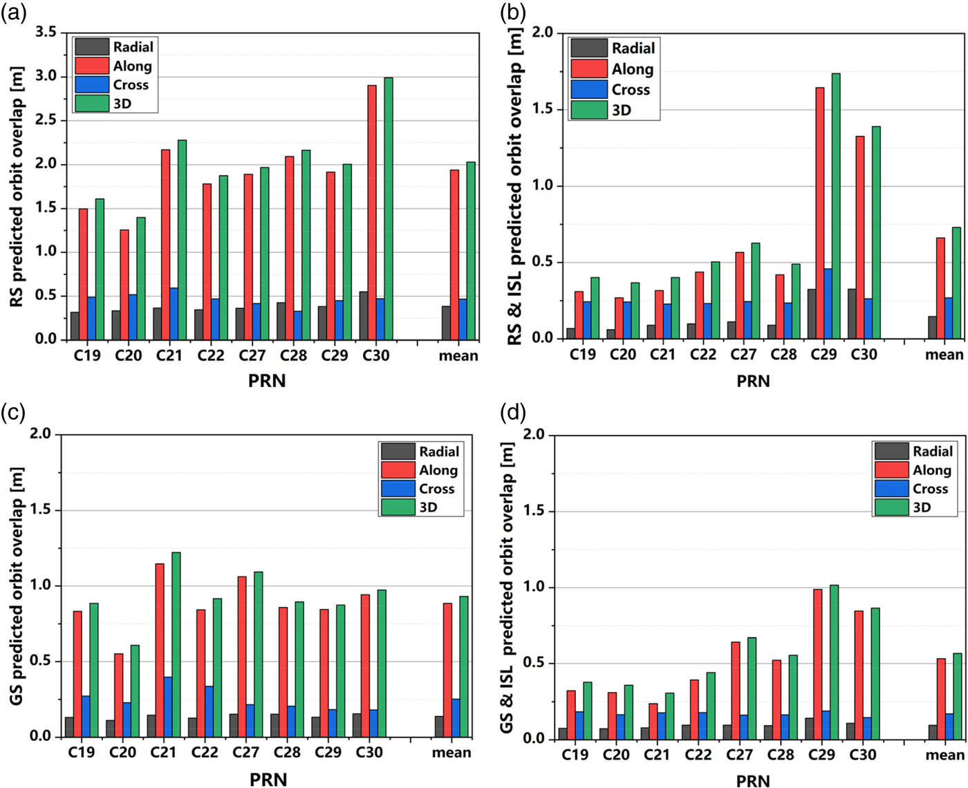
Figure 9. The 24-hour prediction accuracy of BDS-3 satellites of the RS (a), RS and ISL (b), GS (c), and GS and ISL solution (d).
Table 4. Accuracy of 24-hour orbit prediction (unit: m).
The results show that:
(1) ISL measurement can greatly improve the orbit prediction accuracy of BDS-3 satellites for both the RS and the GS solutions. By adding the ISL observation, the 24-hour prediction position accuracy of BDS-3 satellites can be improved from 2·03 m to 0·73 m for the RS solution, which is a 64% improvement and position accuracy is approximately 0·56 m for the GS solution, which is a 40% improvement.
(2) Compared to the RS solution, the ISL observation is more effective than an iGMAS station observation in orbit prediction for BDS-3 satellites. For the RS solution, the position RMS of BDS-3 satellites 24-hour predicted orbit is 2·03 m. By adding the iGMAS observation, the position RMS is decreased to 0·93 m, which is a 54% improvement. By adding the ISL observation, the position RMS is decreased to 0·73 m, which is a 64% improvement, because of the higher accuracy in the along-track direction.
(3) For the GS and ISL solution, the RMS of BDS-3 24-hour predicted orbit in the radial, along-track and cross-track directions are 0·09 m, 0·53 m and 0·11 m, respectively, and the position RMS is 0·56 m.
4.4. Orbit-only URE
The orbit-only User Ranging Error (URE) is mainly used to evaluate the influence of orbit error to users. The calculation methods for satellites at different altitudes are different. For BDS MEO satellites, URE is calculated using Equation (13) (Yang et al., Reference Yang, Yang, Li, Zhou and Tang2017).
 $$URE=\sqrt{\lpar 0{\cdot}99\Delta R\rpar ^2+\lpar 0{\cdot}14\Delta A\rpar ^2+\lpar 0{\cdot}14\Delta C\rpar ^2} $$
where Δ R, Δ A and Δ C are the orbit errors in the radial, along-track and cross-track directions, respectively.
In this section, the overlapping orbit-only URE of different solutions are analysed. The overlapping orbit-only UREs of C19 and C28 are shown in Figures 10(a) and 10(b), respectively. The blue points represent the orbit-only URE of the RS solution, the red ones represent the RS and ISL solution, the yellow ones represent the GS solution and the purple ones represent the GS and ISL solution. The green curve represents the elevation of the satellite relative to ten regional ground stations. The first two-day arc is the determined orbit and the third day arc is the predicted orbit.
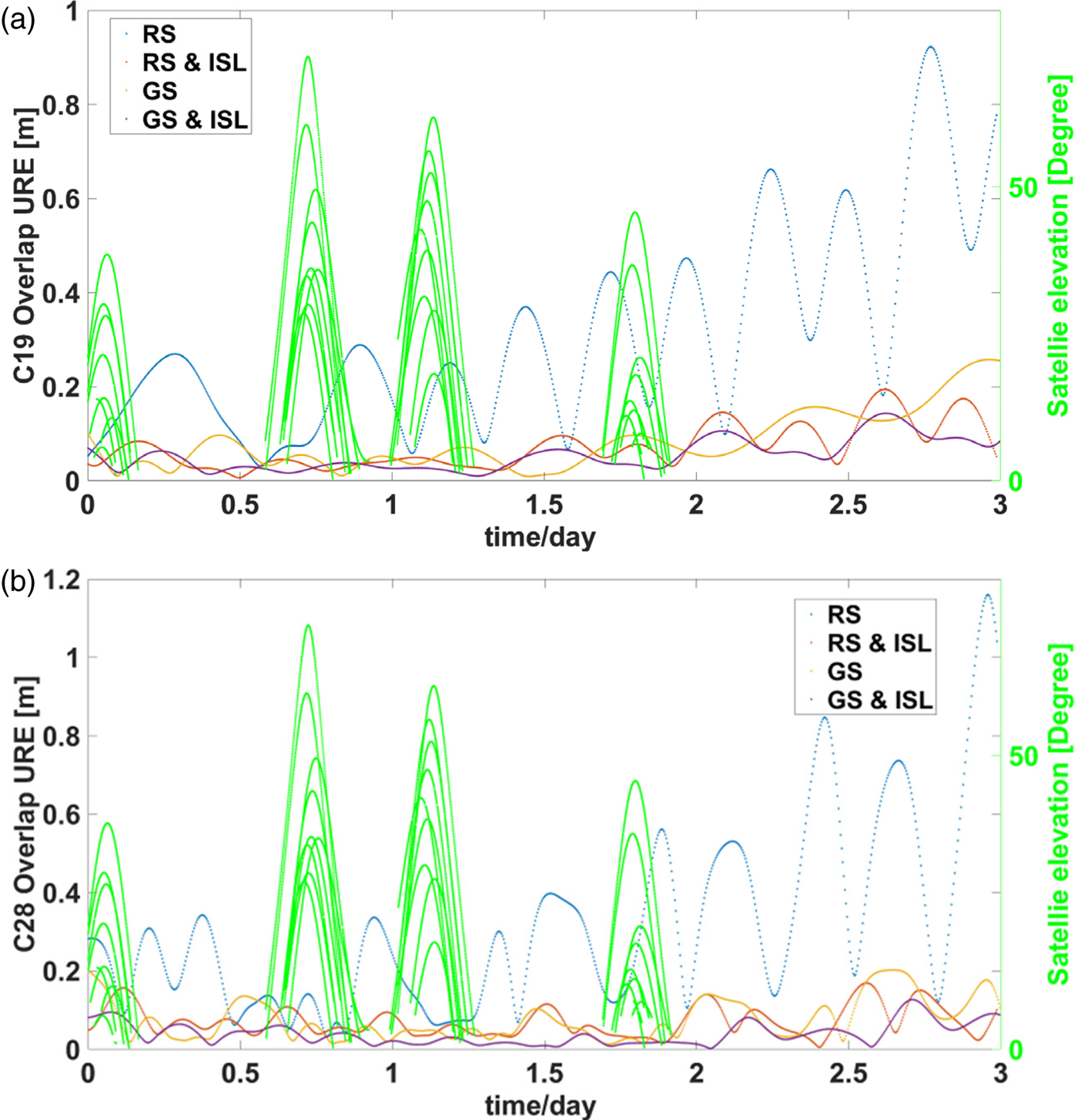
Figure 10. Overlapping orbit-only URE of C19 (a) and C28 (b).
As seen in Figure 10, fluctuations can be readily seen for overlapping orbit-only URE of the RS solution. When an MEO satellite goes out of range of the regional stations on the mainland of China, the orbit accuracy decreases quickly because of missing observation data, and the accuracy of the predicted orbit is poor. By adding the ISL observation, significant difference between the orbit in and out of range of the regional stations can no longer be seen, and the decrease of the orbit prediction accuracy is much slower. The reason is that the ISL can extend the visible arc of the MEO satellites, the problem of rapidly increasing error of the orbit beyond the range of the regional stations is effectively solved, and the accuracy of orbit prediction is significantly improved as well.
5. CONCLUSION
Based on the eight current BDS-3 satellites, the noise level and ranging accuracy of ISL measurements, as well as observation residuals, OOD, orbit prediction accuracy and overlapping orbit-only URE of ISL enhanced orbit determination were analysed. The following conclusions can be drawn. The ISL measurement noise of BDS-3 satellites is about 1~ 3 cm, and the ranging accuracy is about 6 cm. The 3D position RMS of OODs for the RS solution is close to 1 m, which is obviously better than that of BDS-2 MEO and BDS-3-E satellites. By adding ISL observations, the 3D position RMS is equivalent to the GS solution. The ISL observation can also improve the accuracy of the predicted orbit, which is even better than the GS solution. The reason is that the ISL extends the visible arc of the MEO satellites, and the accuracy of orbit prediction is improved.
However, it is worth noting that since BDS-3 is currently in the phase of system construction, there were only eight BDS-3 satellites in operation during the experiment, and the status of ISL is not yet stable enough. In addition, Satellite Laser Ranging (SLR) observation data of BDS-3 satellites was unavailable when the paper was prepared, so it was not possible to conduct an external orbit validation and more research needs to be done in the future.