


1. Introduction
The soft robot is made of flexible materials, which can change its shape and size arbitrarily within a large range. Due to the softness of the materials, soft robots have excellent environmental adaptability and flexibility. Soft robots can imitate the locomotion modes of animals in nature, adapt to environments that humans cannot reach, thus expanding the field of human exploration. By imitating the locomotions of creatures in nature, they can realize the special locomotions of robots in complex environments [Reference Guo, Elgeneidy and Xiang1–Reference Seok, Onal and Cho10].
In recent studies, various soft robots have been developed. Soft and continuum robots have the useful capability of adopting intricate postures and conforming to complex shapes [Reference Umedachi, Vikas and Trimmer11]. Xie et al. [Reference Xie, Domel and An12] produced an octopus robot with a unique tapered geometry actuator. The robot has a conical actuator with suction cups, so it has a better grip, but it needs more force to separate from the plane and surface. Xu et al. [Reference Xu, Liu, Li, Feng, Zheng and Gao13] investigated a four-legged soft robot that can climb over obstacles. Inspired by the crawling behavior of crabs and their structural characteristics, they developed a soft robot that can deliver items over obstacles. Yang et al. [Reference Yang, Tan, Lu and Shen14] proposed a starfish-inspired soft robot with excellent locomotive performance and great environmental adaptability. The microstructures of tube feet can strengthen the driving performance of the robot, reducing the motion resistance from the ground, and enhance the obstacle-climbing ability. Huang et al. [Reference Huang, Xu, Xiao, Hu, Huang and Zhou15] presented a new bionic omnidirectional bending actuator (BOBA) inspired by leeches, caterpillars, and other mollusks. In the field of soft robots, modular soft robots are more popular. The modular nature of these robots enables distributed sensing and computation elements. Onal et al. [Reference Onal and Rus16] described a modular approach to creating soft robotic systems.
The soft crawling robot is one of the main research directions of soft robots [Reference Chen, Hu, Zou, Zhang, Wang and Jin17]. Inspired by nature, scientists have studied and designed many soft crawling robots in the last decade [Reference Wehner, Truby, Fitzgerald, Mosadegh, Whitesides, Lewis and Wood18]. Lu et al. [Reference Lu, Wang and Hu19] developed an annelid-like soft robot based on an improved dielectric elastomer (DE) minimum energy structure actuator to have these annelidan features. The robot can achieve a maximum velocity of 11.5 mm/s and a maximum velocity/mass ratio of 86.25 mm/(minxg). Yu et al. [Reference Yu, Yang, Yu, Cheng and Jiao20] designed a crawling robot actuated by pneumatic foldable actuators (PFAs) based on Miuraori, according to the parallel foldable structure and different control patterns, which can perform different motions. The speed of the robot is about 5 mm/s and it can turn at a speed of about 15 °/s. Jiang et al. [Reference Jiang, Zhang, Wang, Cheng, Zhang and Ding21] proposed a bionic earthworm crawling robot. When inflate and deflate in a designed sequence for each chamber, the maximum crawling speed of the soft robot can reach 150 mm/min, meanwhile, it can stably crawl on smooth planes with different angles (maximum 45 degrees) owning to the suction cup structures. Qin et al. [Reference Qin, Wan and Sun22] proposed a bionic soft robot composed of four modules. Its maximum velocity is 131.6 mm/s (0.25 body length per second) in serpentine locomotion and 65.2 mm/s (0.12 body length per second) in sidewinding locomotion.
In nature, both postural maintenance and rhythm generation are keys to generating adaptive behavior in all animals. This is particularly evident in soft animals such as inchworms, snakes and so on [Reference Umedachi and Trimmer23]. Inchworms have compliant bodies, which allow them to transform their shape and morphology [Reference Niu, Feng, Xie, Jiang, Sheng, Yu and Zeng24, Reference Umedachi, Vikas and Trimmer25]. Zhang et al. [Reference Zhang, Yang, Yan, Zhou, Zou and Gu26] presented a class of inchworm-inspired multimodal soft crawling-climbing robots (SCCRs). Guo et al. [Reference Guo, Zhang, Wang, Li, Hong and Li27] presented an inchworm-inspired soft robot composed of the soft body, the front foot as well as the back foot. Snakes can store elastic potential energy through their soft muscles and skin to help them move in different environments. And the scales on the skin of a snake are an integral part of the snake’s locomotive capabilities [Reference Chang and Vela28]. Transeth et al. [Reference Transeth, Pettersen and LiljebÄck29] gave a survey of the various mathematical models and motion patterns presented for snake robots to help researchers study the locomotion of snake robots. Serrano et al. [Reference Serrano, Chang, Zhang and Vela30] presented a robotic snake design that incorporates rigid scales in the casing of each module. So inchworms and snakes are ideal objects for soft crawling robots.
In the paper, in order to better reflect the inchworm and snake locomotion, a novel modular soft robot configuration is proposed, which is composed of a head module, a tail module and three body modules. A method of discretizing the body of the robot into a series of connecting rods is proposed to analyze the force of the robot in motion. A new motion mode is proposed, which is the motion of imitation snake and inchworm. This robot uses the head and tail module to change the friction for motion, which can realize turning and crawling motion.
2. Design and modeling
In this section, the modular soft robot is presented. The nonlinear deformation characteristics of the body module are analyzed, and the manufacturing parameters of the body module are determined.
2.1 Design of the modular soft robot
The modular soft robot is composed of one head module, three body modules and one tail module (Fig. 1(a)). For each module, an inextensible limiting layer and two silicone bladders with a row of air chambers are prepared by casting first. Then, two silicone bladders are bonded with the inextensible limiting layer. The side of the middle part of the air chamber is perforated and connected with the pipe. A detachable 3D printing connecting element is installed on the front and rear of the module respectively, and the module is connected with the module through the 3D printing connecting element. The modular soft robot has multiple body modules. Experiments show that when the number of body modules is less than three, the motion effect of the robot is poor. Therefore, three body modules are used in this robot.
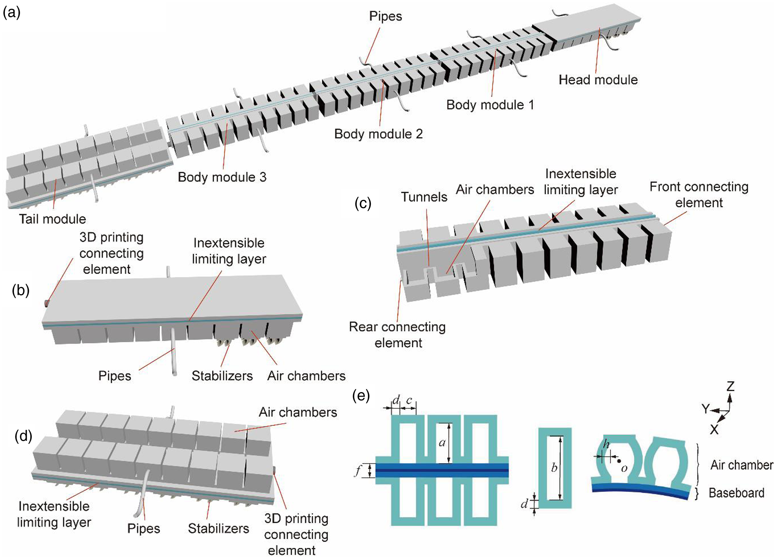
Figure 1. The modular soft robot. (a) The overall structure of the modular soft robot. (b) The head module. (c) The body module. (d) The tail module. (e) Schematic diagram of the air chamber size.
Each module is made of silicone rubber. The head module and the tail module are used to maintain the motion direction and stability of the robot (Fig. 1(b) and (d)). The head module consists of two parallel rows of air chambers, the inextensible limiting layer and the bristles (Fig. 1(b)). There are nine air chambers in each row, and the pipe is connected with the middle air chamber. The bristles are located at the bottom of the head module. The bristles are positioned similar to the setas of an earthworm [Reference Liu, Ozkan, Goldman and Hammond31] or the scales of a snake [Reference Huq, Khan, Shafie, Billah and Ahmmad32, Reference Huq33]. The bristles work as anchors during the locomotion. Its purpose is to assist the robot to produce large unidirectional friction on the ground in the process of locomotion. The bristles are made of TPU material through 3D printing and have certain flexibility(Fig. 3(d) and (e)). During inflation, the front end of the head module is lifted, and the rear end contacts the ground. In order to make the friction coefficient of the head module different from the ground during inflation and deflation, the bristles of the head module are installed at the front end of the bottom. By controlling the inflation strategy of two rows of air chambers in the head module, the robot can move in a crawl or turn.
The structure of each body module is similar to that of PneuNet [Reference de Payrebrune and O’Reilly34]. Each body module is divided into three parts. They are ten interconnected air chambers in parallel, the inextensible limiting layer in the middle and the connecting elements in the front and rear respectively [Reference Wu, Jiangbei and Yanqiong35]. Each body module is connected by a tunnel at the bottom of the air chamber (Fig. 1(c)). Each body module has two pipes, each of which is inserted into the middle air chamber of the bladder.
During inflation, the air passing through the pipe reaches the middle air chamber of the bladder, and then reaches each air chamber through the tunnel. With the increase of air chamber pressure, each air chamber expands to drive the body module to bend.
The tail module has two parallel rows of air chambers, the inextensible limiting layer and the bristles (Fig. 1(d)). Its bristles are also located at the bottom. Different from the head module, the tail module has more bristles. The reason is that the tail module can be lifted as a whole when inflated, and only both ends of the tail module are in contact with the ground, so more bristles can be installed. Bristles provide a smaller tangential friction coefficient in the forward direction and a larger tangential friction coefficient in the backward direction.
2.2 Manufacturing parameters of the air chambers
In this paper, the air chamber is taken as the research object to analyze the deformation characteristics of the bladder. By referring to the Yeoh model [Reference Jianlong, Guangjuan and Zhengwei36], the elastic properties of silicone rubber can be described in terms of a strain energy function.
 \begin{align}W = f({I_1},{I_2},{I_3})\end{align}
where W is the strain energy density, and I
1, I
2 and I
3 are three invariants of the deformation tensor. In order to simplify the model, Yeoh [Reference Jianlong, Guangjuan and Zhengwei36] suggested neglecting
 $\partial W/\partial {I_2}$
and equating it to zero. Silicone rubber is almost incompressible. For incompressible materials, I
3
= 1. The binomial parameter form [Reference Yeoh37] of the strain energy function is,
$\partial W/\partial {I_2}$
and equating it to zero. Silicone rubber is almost incompressible. For incompressible materials, I
3
= 1. The binomial parameter form [Reference Yeoh37] of the strain energy function is,
 \begin{align}W = {C_1}({I_1} - 3) + {C_2}{({I_1} - 3)^2}\end{align}
where C 1, C 2 are material coefficients, which are determined by tensile tests (BYES, 5000 N, 700 mm, China). According to the standard ASTMD412 and then curve fitting, which results in C 1 = 0.112 and C 2 = 0.019.
 \begin{align}\tau = ({\tau _x},{\tau _y},{\tau _z}) = \left(0,hg\left(\frac{{2x}}{a}\right)g\left(\frac{{2z}}{b}\right),0\right)\end{align}
 \begin{align}E = \int {Wdv} = \int_{\frac{c}{2}}^{\frac{c}{2} + d} {\int_{ - \frac{b}{2}}^{\frac{b}{2}} {\int_{ - \frac{a}{2}}^{\frac{a}{2}} {{C_1}({I_1} - 3) + {C_2}{{({I_1} - 3)}^2}dxdydz} } } \end{align}
 \begin{align}{I_1} = tr\left[\left({I_n} + \frac{{\partial (u)}}{{\partial (x,y,z)}}\right){\left({I_n} + \frac{{\partial (u)}}{{\partial (x,y,z)}}\right)^T}\right]\end{align}
where h is the maximum deformation of the air chamber expansion wall. o is located at the center of a single air chamber as the coordinate origin, and Y direction is the expansion direction of the air chamber wall. In the process of inflation, any point on the air chamber wall moves in the Y direction while the X and Z coordinates remain unchanged (Fig. 1(e)). The displacement of any point on the left air chamber wall is τ, as shown in Eq. (3). By integrating the left air chamber wall, the corresponding strain energy function is obtained, as shown in Eqs. (4) and (5).
ν is the volume of a single left air chamber wall, I n is an identity matrix and g(x) is called the profile function. a,b,c and d are manufacturing parameters of the air chamber(Fig. 1(e)).
 \begin{align}E = 4{C_1}{B_0}{B_1}\left(\frac{a}{b} + \frac{b}{a}\right){h^2}d + 16{C_2}{B_2}{B_3}\left(\frac{{{a^2}}}{{{b^2}}} + \frac{{{b^2}}}{{{a^2}}} + 2\right)\frac{{{h^4}d}}{{ab}}\end{align}
where
 \begin{align}{B_0} & = \int_0^1 {{{[g'(x)]}^2}dx} \;,\;{B_1} = \int_0^1 {{{[g(x)]}^2}dx} \;,\nonumber\\[5pt] {B_2} & = \int_0^1 {{{[g'(x)]}^4}dx} \;,\;{B_3} = \int_0^1 {{{[g(x)]}^4}dx} \end{align}
B
0, B
1, B
2, B
3 in Eq. (7) are constants only determined by the profile function g(x). Generally, g(x) should comply with the actual deformation of the left air chamber wall as following conditions,
 $g(0) = 1,g( - 1) = g(1) = 0,g'(0) = 0$
.
$g(0) = 1,g( - 1) = g(1) = 0,g'(0) = 0$
.
To simplify the function, we construct the function
 $g(x) = 1 - {x^2}$
. Then, the constants are calculated according to g(x), which results in
$g(x) = 1 - {x^2}$
. Then, the constants are calculated according to g(x), which results in
 ${B_0}{B_1} = \dfrac{{32}}{{45}}$
,
${B_0}{B_1} = \dfrac{{32}}{{45}}$
,
 ${B_2}{B_3} = \dfrac{{2048}}{{1575}}$
. By using the principle of virtual work, the expansion pressure P is connected with the maximum deformation h, and Eq. (8) is obtained. The left side is the virtual change of the total strain energy of the left air chamber wall with the expansion height, and the right side is the virtual work of the left air chamber wall under the expansion pressure.
${B_2}{B_3} = \dfrac{{2048}}{{1575}}$
. By using the principle of virtual work, the expansion pressure P is connected with the maximum deformation h, and Eq. (8) is obtained. The left side is the virtual change of the total strain energy of the left air chamber wall with the expansion height, and the right side is the virtual work of the left air chamber wall under the expansion pressure.
 \begin{align}\frac{{dE(h)}}{{dh}}\delta h = P\frac{{dV(h)}}{{dh}}\delta h\end{align}
 \begin{align}V(h) = hab\int_0^1 {{{[g(x)]}^2}dx} \end{align}
Among Eq. (9), V(h) is the increased volume inside the air chamber after inflating. Among Eqs. (6)–(9), the relationship between the pressure P inside the air chamber and the maximum deformation h of the air chamber expansion wall can be obtained.
 \begin{align}P = 2.965\left(\frac{{{a^2}}}{{{b^2}}} + \frac{{{b^2}}}{{{a^2}}} + 2\right)\frac{{{h^3}d}}{{{a^2}{b^2}}}\end{align}
According to Eq. (10), the pressure P is proportional to the cubic of the deformation h of the air chamber expansion wall. With the increase of the pressure in the air chamber, the expansion speed of the air chamber slows down (Fig. 2). The manufacturing parameters of the air chamber are shown in Table I. Parameters a, b and d are obtained from Eq. (10) and the functional relationship of a, b, d and P is shown in Fig. 2. By determining parameters a, b and d, the pressure P can reach the maximum value. Inextensible layer thickness f and air chambers width c have little influence on the deformation of the air chamber during inflation. Therefore, the parameters c and f are determined by comprehensively considering the overall size of the modular soft robot during manufacturing process.

Figure 2. The relationship between the inflation pressure P and the manufacturing parameters and maximum deformation.
When the pressure P increases, the deformation of the air chamber increases. The bending angle of the body module will also increase. However, in the inflation experiment, when the pressure P exceeds 120 kPa, the structure of the body module will be damaged. Considering the characteristics of silicone rubber and the safety of the body module, the air pressure of the body module is set at 90 kPa. The structure of the head module is similar to that of the tail module and different from that of the body module. The air pressures of the head module and the tail module are also different from that of the body module. In the inflation experiment, the head module and the tail module can bear more inflation pressure than the body module. Considering the safety of the modules, the air pressure of the head module and the tail module is set at 100 kPa.
3. Locomotion analysis
3.1 The locomotion principle
The modular soft robot refers to the motion of inchworm [Reference Plaut38] and snake [Reference Cicconofri and Desimone39]. When the inchworm moves, its body arches and generates driving force through body deformation. At the same time, the foot of the inchworm contacts the ground, resulting in different friction between the front and rear ends of the inchworm [Reference Yamamoto, Sakama and Kamimura40]. When the friction force at the front end is large, the inchworm’s body shrinks forward. When the rear-end friction is large, the inchworm body extends forward.
Table I. The manufacturing parameters of the air chamber.

For snakes, their bodies form a series of sinusoidal curves in locomotion [Reference Wang, Lin, Chong, Whitman, Travers, Goldman and Choset41]. When the snake moves, the snake will rely on the friction between the abdominal scale and the ground to generate a driving force, so that the snake can move freely in the sand, grass and other places [Reference Tian, Matsuno and Ma42–Reference Xiao, Bing and Huang44]. By comparing the locomotions of inchworms and snakes, it is found that they are actuated by the body. The feet/scales generate friction by contacting the ground. They move their bodies forward by overcoming the friction. According to this principle, the structure of a modular soft robot is designed. When the robot moves, we simplify the robot into a head module, tail module and body modules (Fig. 3(a)).

Figure 3. Structure and force analysis of modular soft robot. (a) The structure division of the modular soft robot, which is composed of one head module, one tail module and three body modules. (b) The force and torque in the continuous flexible model. (c) The bristle is mounted on the tail module. (d) Physical diagram of bristle.
We simplified the body modules between the head module and tail module into a series of continuous flexible models (model 1, model 2 and model 3) for mechanical analysis. By treating the body modules as a series of continuous flexible models with a length of l, the force of the robot in locomotion is analyzed. Then, a novel bristle is proposed to help the modular soft robot obtain the unidirectional friction in locomotion (Fig. 3(d)). The force condition for robot locomotion is analyzed (Fig. 3(b)). Assume that i = 0 is the starting point of the curve, corresponding to point A. Φ is the angle of the body module at point B relative to the traveling direction. T i indicates the bending torque, κ i indicates the curvature, f ti indicates the force per unit length acting on the ground in the tangential direction, and f ni indicates the force per unit length acting on the ground in the normal direction. Eqs. (11)–(12) indicate the relationship between the bending torque T i, curvature κ i, and forces(f ti, f ni ) that are applied to the ground. The expression of curvature κ i is shown in Eq. (13) [Reference Hirose and Yamada45].
 \begin{align}{f_{ti}} = \frac{{d{T_i}}}{{di}}{\kappa _i}\end{align}
 \begin{align}{f_{ni}} = \frac{{{d^2}{T_i}}}{{d{i^2}}}\end{align}
 \begin{align}{\kappa _i} = - \frac{{2\pi \varphi }}{{3l}}\cos \left(\frac{{2\pi }}{{3l}}i\right)\end{align}
The tangential force and normal force are the internal forces produced by the modular soft robot in the locomotion. There are two kinematic conditions for the modular soft robot to move forward. (a) It is necessary to have enough propulsion force to overcome the sliding friction along the curve. (b) The modular soft robot must have the ability to prevent normal sliding. Therefore, it is necessary to consider the tangential friction f mt and the normal friction f mn caused by the contact between the modular soft robot and the ground. In the process of locomotion, if the modular soft robot needs to slide forward, the resistance in the tangential direction is sliding friction force f mt, the tangential force needs to satisfy the following Eq. (14) [Reference Transeth, Pettersen and LiljebÄck29].
 \begin{align}{f_t} \ge {f_{m\,\,t}}\end{align}
In order to move forward with enough driving force, the modular soft robot should have a smaller tangential sliding friction force and a larger tangential force f t . Tangential force f t is limited by the driving force of the modular soft robot. The tangential sliding friction meets the following Eq. (15) [Reference Transeth, Pettersen and LiljebÄck29].
 \begin{align}{f_{mt}} = {\mu _{mt}}mg\end{align}
where μ mt is the tangential sliding friction coefficient.
Once the structure of the modular soft robot is designed, the weight will be determined. Therefore, the smaller the tangential sliding friction coefficient is, the smaller the corresponding tangential sliding friction force will be. In the normal direction, it is necessary to prevent the modular soft robot from producing lateral displacement, and the normal force before the modular soft robot has normal sliding is static friction force, so the normal force f n should be less than the maximum static friction force f mnmax of modular soft robot in normal direction as shown in Eq. (16) [Reference Transeth, Pettersen and LiljebÄck29].
 \begin{align}{f_n} = {f_{m\,\,n}} \le {f_{m\,n\,\max }}\end{align}
In order to avoid side sliding, the normal friction coefficient μ mn should be increased as much as possible to increase the normal maximum static friction f mn . In order to simplify the model of the modular soft robot, the bristles on the head and tail modules are used to provide the tangential and normal friction forces.
When the module is not equipped with bristles, the tangential friction coefficient is μ t1 and the normal friction coefficient is μ n1 . When the module is equipped with bristles, the forward tangential friction coefficient is μ t2 , the backward tangential friction coefficient is μ t3 , and the normal friction coefficient is μ n2 (Fig. 4). The results are shown in Table II. It can be found that the bristle provides a large normal friction coefficient. In order to prevent the modular soft robot from lateral displacement. The bristle provides a smaller tangential friction coefficient in the forward direction and a larger tangential friction coefficient in the backward direction. When the modular soft robot moves, the head module and the tail module bend up and down in turn. When body modules are inflated and bent, the tail module bends, and the head module suffers a large tangential friction force, and the modular soft robot moves forward. When body modules deflate, the head module bends and the tail module suffers a large tangential friction force, and the modular soft robot moves forward.

Figure 4. Friction coefficient test on the module of the modular soft robot. (a) The tangential friction coefficient test of the module without bristles. (b) The normal friction coefficient test of the module without bristles. (c) The tangential friction coefficient test of the forward direction of the module with bristles. (d) The tangential friction coefficient test in the backward direction of the module with bristles. (e) The normal friction coefficient test of the module with bristles.
Table II. Friction coefficient of module under different conditions.

It is found from Table II that when the module is not equipped with bristles, the normal friction coefficient μ n1 is less than the normal friction coefficient μ n2 of the module equipped with bristles. In locomotion, the modular soft robot equipped with bristles has a larger normal friction coefficient. After installing the bristles, the modular soft robot can maintain a straight line without deflection.
3.2 The locomotion mode
A novel locomotion mode is proposed. The locomotion of the modular soft robot is similar to that of inchworms and snakes. The head module plays the role of the inchworm’s head and snake’s head to determine the direction of the locomotion. The body modules act as the body of the inchworm and the snake to provide the driving force. The tail module plays the role of inchworms’ tail and snake’s tail so that the modular soft robot can maintain the proper motion direction without deflection. The forward linear locomotion of modular soft robots is divided into five stages (Fig. 5).

Figure 5. Motion strategy of the modular soft robot. (a) The locomotion strategy of the modular soft robot. (b) Bending strategy of body modules with different cycles. (c) Bending strategy of modular soft robot when turning.
Stage A: Locomotion begins. Stage B: Three body modules are inflated in turn. The direction of body module inflation is determined by the inflation sequence (Fig. 5(b)). The tail module is inflated and bent, and the head module is not inflated. At this time, the head module provides a large tangential friction force, and the modular soft robot moves forward. Stage C: Three body modules keep the inflation pressure unchanged. The head module is inflated and bent, and the tail module is deflated and stretched. Stage D: Keep the head module and the tail module unchanged. Three body modules are deflated and stretched. At this time, the tail module provides greater tangential friction force, and the modular soft robot continues to move forward. Stage E: The head module is deflated and extended. Body modules and the tail module remain unchanged. At this time, the modular soft robot completes a cycle of locomotion, and the forward distance is S.
It should be noted that the bending of the body module changes periodically in different periods. In the singular cycle, the bending directions of the three body modules (from right to left in Fig. 5(b)) are: left, right and left. Similarly, in the even cycle, the bending directions of the three body modules (from right to left in Fig. 5(b)) are: right, left, right.
In addition to crawling locomotion, the modular soft robot can also turn. The inflation sequence of turning locomotion is different from that of straight locomotion. When the modular soft robot turns to the right, body modules (from right to left in Fig. 5(c)) bend to the left, left and right respectively. Similarly, when the modular soft robot turns to the left, body modules bend to the right, right, left.
4. Experiment
4.1 Control system
The control system of the modular soft robot consists of a pneumatic path and an electronic path. The control system diagram is shown in appendix. It mainly includes five modules, power supply (DC 12V), air pump (90 L/min), pressure reducing valve (IR2010-02), micro solenoid valve (CY0520F) and microcontroller (Arduino Mega 2560). K1,2.10 are micro solenoid valves (CY0520F). We use 10 two-position three-way solenoid valves to control the inflation and deflation of five modules. The inflation and deflation of each module are independent.
The control system is open-loop design. Open-loop control uses fewer devices and no sensors. The overall design of the modular soft robot is more concise. For the modular soft robot, open-loop control can provide stable locomotion control.
4.2 Connecting elements test
For the modular soft robot, reconfigurability is one of its characteristics. If the environment is harsh, the structure of the modular soft robot may be damaged by environmental factors during movement. For traditional soft robots, structural failure means that the robot can not continue to work [Reference Zhang, Zhu and Lin46, Reference Wang, Min and Fei47]. Therefore, the modular design concept is introduced into the modular soft robot. The modular soft robot is divided into several modules. When any module is destroyed in motion. The spare module can be used to replace the damaged module (Fig. 6(c)).

Figure 6. Connection between modules. (a) Connection elements of the body module and the tail module. (b) The strong magnet (c) Assembly process diagram of the modular soft robot.
Body modules are connected by 3D printing connecting elements. The head module is connected with body module 1, and body module 3 is connected with the tail module. This connection is made with a strong magnet (Fig. 6(a)). The size of the strong magnet is 10 mm × 5 mm × 3 mm (Fig. 6(b)). The tensile force can reach 4.2 N. The attraction distance is less than 13.5 mm. The mass of a module is about 70 g, so it can complete the connection function in locomotion.
The test of the connection effect between the body module and the tail module is shown in Fig. 7. When the body module is close to the tail module, it will be automatically connected with the tail module. The body module is pulled to move. When the tail module does not fall off, the moving speed of the module is more than 50 mm/s. The pull force provided by the connecting element can meet the normal locomotion of the modular soft robot. When module A is damaged in locomotion. Module B can be used to replace damaged module A. After the replacement, the modular soft robot can continue to move (Fig. 6(c)).

Figure 7. The test of the connection between the body module and the tail module (a) Body module and the tail module. (b) The body module approaches the tail module. (c) The body module is automatically connected when it is close to the tail module. (d) The body module is pulled to move.
4.3 Locomotion control
The velocity of the modular soft robot is determined by the driving force provided by the bending deformation and the friction force between the modular soft robot and the ground. In locomotion, the body module does not change the friction force of the modular soft robot. Therefore, the larger the driving pressure, the larger the bending deformation of the body module, and the larger the driving force. The driving pressure of it is set to 90 kpa to ensure the reliability of the modular soft robot in locomotion. After the driving pressure is set, the driving force of the modular soft robot in locomotion is also determined.
The friction between the modular soft robot and the ground is mainly determined by the head module and the tail module. When the air pressure of the head module and the tail module changes, the contact area between the head module and the tail module and the ground changes. The contact area between the bristles installed on head and tail modules and the ground also changes. The deformation diagram of the modular soft robot is shown in Fig. 8(a). The head module and the tail module are at different air pressures when the air pressure of the body module is 90 kpa. At this time, the friction coefficient between the head module and the tail module changes with the contact area between the bristle and the ground.

Figure 8. The deformation diagram of the modular soft robot. (a) The air pressure of the body module is 90 kpa, the head module and the tail module are at different air pressures. (b) The relationship between the air pressure P(kPa), the moving time t(s) and the forward distance S(mm).
During different stages of locomotion (Stage A, Stage B, Stage C, Stage D and Stage E), the air pressure of the head module and the tail module will change. Therefore, the friction coefficient between the modular soft robot and the ground is also different in different stages. Using this change of friction between the head module and the tail module, the crawling locomotion of modular soft robot is realized.
Through the experiment, we can get the relationship between the air pressure P(kPa) of the head module and the tail module, the moving time t(s) of the modular soft robot and the forward distance S(mm) of the modular soft robot (Fig. 8(b)). It can be found that the higher the inflation pressure P(kPa) of the head module and the tail module, the smaller the contact area between the head and tail module and the ground. The friction between the modular soft robot and the ground decreases. At this time, in the same period of time t(s), the forward distance increases.
4.4 Crawling and turning experiment
In order to test the moving ability of the modular soft robot on a rough surface, the modular soft robot is placed on a rough blanket for the crawling experiment. In the crawling experiment, the inflation pressure of the body module is 90 kPa, and that of the head module and tail module is 100 kPa. After five cycles of locomotion, the average speed is 15.53 mm/s (0.03 body length per second) (Fig. 9).

Figure 9. The crawling experiments of the modular soft robot.
For the modular soft robot, it can turn. The modular soft robot is placed on a rough blanket for turning experiments. In the turning experiment, the inflation pressure of the body module is 90 kPa, and that of the head module and the tail module is 100 kPa. The soft robot turns right (Fig. 10). The soft robot turns 52.3° to the right in 41.1 s and the average turning speed is 1.273 °/s.

Figure 10. The turning experiments of the modular soft robot.
5. Conclusion
This paper presents a novel modular soft robot. It consists of one head module, one tail module and three body modules. Each body module is composed of three parts which are interconnected air chambers in parallel, an inextensible limiting layer in the middle and connecting elements in the front and rear. The head module and the tail module are made of interconnected air chambers, an inextensible limiting layer and bristles. The strain energy function of the air chambers is established, and the nonlinear deformation characteristic of it is analyzed. Considering the characteristics of silicone rubber and the safety of the body module, the air pressure of the body module is set at 90 kpa. The air pressure of the head module and the tail module is set at 100 kpa.
By dividing the body of the robot into a series of continuous flexible models the forces of the robot in locomotion are analyzed. Then, a novel bristle is proposed to help the modular soft robot obtain the unidirectional friction in locomotion. A novel locomotion mode is proposed. The head module and the tail module are used to provide friction force. Three body modules are used to provide the driving force.
The control system of the modular soft robot is established. Based on an inflation and deflation control method, the modular soft robot can crawl and turn by controlling the air pressure of different modules. The crawling speed of the modular soft robot can reach 15.53 mm/s (0.03 body length per second) and its turning speed can reach 1.273 °/s. The relationship between the inflation pressure of the head module and the tail module, the moving time and the forward distance of the modular soft robot is established by experiments.
6. Further work
Because of its soft structure, the modular soft robot can be used in the complex and changeable environments. This kind of robot is also useful in search, rescue and environmental detection missions that are inaccessible to humans or rigid robots. In order to improve the locomotion accuracy of the modular soft robot, we will add more sensors to it. For the modular soft robot, it is also very important to reorganize the module configuration and detect the locomotion effect under multiple configurations. Future work will focus on the integration and configuration exploration of this kind of soft robot, and apply it to different environments. For the modular soft robot, the long air pipes will affect the search and rescue work of the robot. Therefore, it is considered to use a micro air pump and integrate the air pump into the modular soft robot.
Acknowledegement
This work was supported by Institute of Medical Robotics of Shanghai Jiao Tong University under Grant No. IMR2019KY01, National Natural Science Foundation of China under Grant No. 51875335, Project No. 2021Szvup078, TMSK-2021-110.
Authors’ contributions
Zhaoyu Liu designed and manufactured a modular soft robot. Completed the modeling and experimental part.
Yuxuan Wang contributed significantly to analysis and manuscript preparation.
Jiangbei Wang performed the data analyses.
Yanqiong Fei helped perform the analysis with constructive discussions.
Conflict of interest
The authors declare that they have no conflict of interest.
Appendix
The control system of the modular soft robot consists of a pneumatic path and an electronic path in shown in Fig. 11.

Figure 11. The control system of the modular soft robot.


