


1. INTRODUCTION
Since the beginning of the twenty-first century, deep space exploration has become a hot issue again. Uncertainty and a hostile deep space environment put high demands on the accuracy and reliability of position for Deep Space Explorers (DSEs) (William, Reference William2005). At present, navigation for DSEs is mostly performed by ground-based tracking and control systems. However, the long distance between DSEs and Earth brings large time delays and greatly degrades the consequent positioning accuracy. In order to improve the reliability and enhance the independent viability of DSEs, research on autonomous navigation systems for DSEs is necessary (Zheng et al., Reference Zheng, Wang and Tang2015).
As the number of spacecraft in simultaneous operation continues to grow, an enormous interplanetary communication network among different spacecraft and ground-based systems will be formed. Utilising this network to provide navigation services for DSEs is feasible. Since 2010, the National Aeronautics and Space Administration (NASA) integrated network for Space Communications and Navigation (SCaN) has been in its definition phase. It is intended to integrate NASA's three existing network elements, that is, the Space Network, the Near Earth Network and the Deep Space Network into a single network. It is also responsible for providing communications and navigation services to space flight missions throughout the solar system (Jennings et al., Reference Jennings, Borgen, Nguyen, Segui, Stoenescu, Wang, Woo, Barritt, Chevalier and Eddy2009; Tai et al., Reference Tai, Wright and Prior2012). More recently, in 2015, NASA proposed the Multi-Autonomous Positioning System (MAPS), which has already been implemented and routinely used for Martian communications, through the use of the Mars Reconnaissance Orbiter and Mars Odyssey spacecraft. The growth of MAPS will continue through the Mars Atmosphere and Volatile Evolution (MAVEN) project and future commercial Mars telecom orbiters (Anzalone et al., Reference Anzalone, Becker, Crump and Heater2015). Both the integrated network for SCaN and MAPS rely extensively on ground-based operations for estimation and control of spacecraft trajectories. In order to reduce the dependence of navigation systems on ground-based operations and achieve more autonomy, a navigation reference that does not depend on artificial beacons is desirable.
In this paper, we propose an interplanetary autonomous navigation network which is independent of the ground system. It is named the Internet of Spacecraft (IoS) and it is composed of host spacecraft and client spacecraft. The former perform as the absolute reference that depends on some autonomous navigation methods and the latter is served by other spacecraft members of the IoS through inter-satellite links. In addition, this network is not a simple extension of the constellation. Its configuration is flexible such that any client spacecraft that has installed inter-satellite ranging equipment can be added into this network and client spacecraft can also be treated as host spacecraft after their positions have been determined.
The remainder of this paper is organised as follows. Section 2 describes the concept and the developed application mode of the proposed IoS network. Section 3 designs a specific application scheme that supports a flight from the Earth to Mars and Section 4 provides the conclusions.
2. THE GENERAL FRAMEWORK OF IoS
The IoS is an interplanetary autonomous navigation network which can cover the whole Solar System. The spacecraft of the IoS can be divided into two parts, namely host spacecraft and client spacecraft. The host spacecraft are settled near to some planets such as the Earth, Mars and so on. They form the absolute reference of the IoS and their positions are determined by autonomous navigation methods. The client spacecraft are launched for space missions on which inter-satellite ranging equipment is installed to communicate with others and their positions are determined by inter-satellite links. There are three navigation and communication modes for client spacecraft, which can be programmed for different flight phases. These three modes are described as follows.
Mode 1 : client spacecraft determine their own positions by communicating with the host spacecraft.
Mode 2 : client spacecraft obtain navigation information from the host spacecraft as well as their own equipment.
Mode 3 : client spacecraft only communicate with other client spacecraft to get navigation information.
This network is not a simple extension of the navigation constellation. It possesses several characteristics and advantages. Firstly, the reference of IoS is independent of ground-based tracking and control systems. Their positions and velocities can be obtained by x-ray pulsar-based navigation (Sheikh and Pines, Reference Sheikh and Pines2006; Sheikh et al., Reference Sheikh, Pines and Ray2006; Wang et al., Reference Wang, Zheng, Sun and Li2013), inter-satellite links or other autonomous navigation methods (Xiong et al., Reference Xiong, Wei and Liu2013). Secondly, both configuration of this network and numbers of the client spacecraft are flexible. We do not need to design the configuration of the whole network, and spacecraft installed with compatible inter-satellite ranging equipment can be added in this network and obtain an autonomous navigation service by communication with others. Finally, arbitrary IoS spacecraft can provide navigation information for the others. After determining their own positions, IoS spacecraft can transmit their position information. Thus, these client spacecraft can also be treated as host spacecraft.
Figure 1 shows a concept sketch of the IoS that can provide navigation information for the whole Solar System. As time goes by, the number of DSEs or interplanetary spacecraft will continuously increase. While they implement their own tasks, they can also be treated as newly joined spacecraft of the IoS at the same time, thus there would be more and more spacecraft in the IoS. As a result, this network would be upgraded, and its coverage could be expanded to further places. Finally, a highly reliable, efficient and low-cost interplanetary autonomous navigation network is expected to be formed.
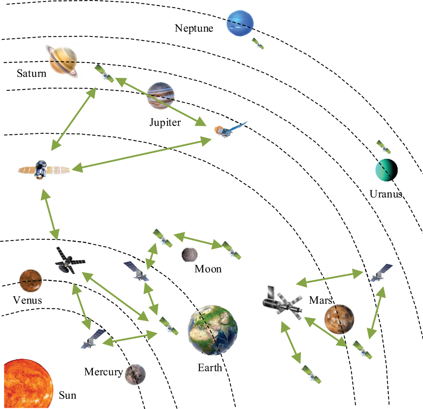
Figure 1. A concept sketch of the IoS that covers the whole Solar System.
3. A DETAILED DESIGN FOR IoS THAT SUPPORTS THE FLIGHT FROM EARTH TO MARS
Currently, Mars exploration is a hot space exploration topic (Bell et al., Reference Bell, Cesarone, Ely and Edwards2000; Grotzinger et al., Reference Grotzinger, Crisp, Vasavada, Anderson, Baker, Barry, Blake, Conrad, Edgett, Ferdowski, Gellert, Gilbert, Golombek, Gomez-Elvir, Hassler, Jandura, Litvak, Mahaffy, Maki, Meyer, Malin, Mitrofanov, Simmonds, Vaniman, Welch and Wiens2012; Martin-Mur et al., Reference Martin-Mur, Kruizinga and Wong2013), and a specific application scheme for IoS supporting a flight from the Earth to Mars is designed in this section.
3.1. Design of the IoS reference
As introduced in Section 2, the host spacecraft are the absolute reference for the whole network. To design the IoS reference, the client spacecraft's space region should be first ascertained. Then, we need to design the orbit of the reference spacecraft to realise geometrical coverage of the client spacecraft. Next, the physical coverage should be guaranteed, that is, the signal intensity should be strong enough to be received. Finally, high-accuracy autonomous navigation methods should be applied to the host spacecraft. Therefore, we design the reference of IoS through these several aspects, that is including design of the orbit, design of the physical coverage and the autonomous navigation method applied for the reference.
3.1.1. Design of the orbit
The client spacecraft's space region, geometrical configuration and orbital stability are taken into account in designing the orbit.
Firstly, we consider that the target users are Mars probes. Their mission phases can usually be divided into a launching phase, cruising phase, and the orbit around Mars (Miele and Wang, Reference Miele and Wang1999). As shown in Figure 2, the launching phase is located in the Earth's sphere of influence. Then the spacecraft takes a long journey along an interplanetary orbit around the Sun, which is the cruising phase. After that, the spacecraft inserts into orbit around Mars. All of these phases should be covered by the IoS.
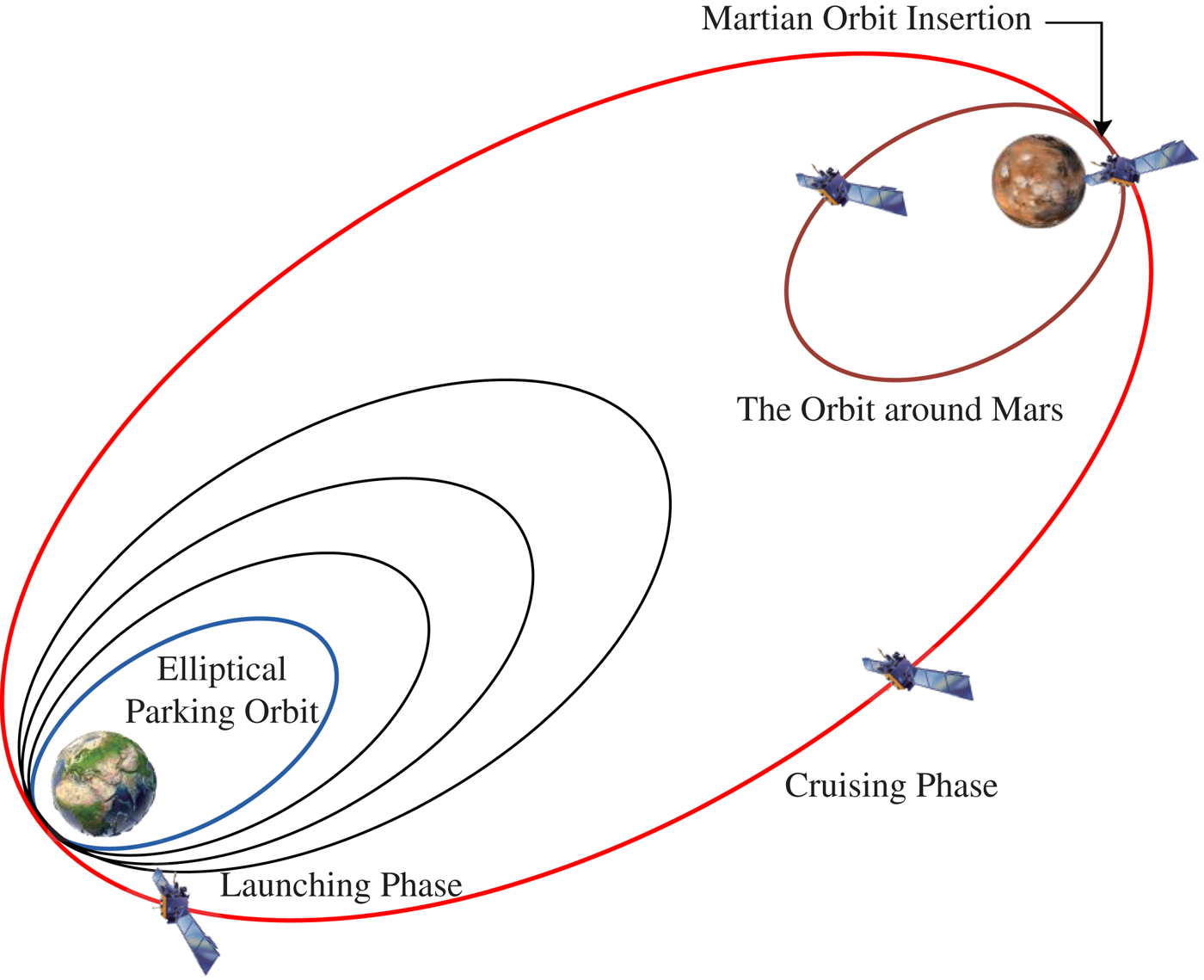
Figure 2. Schematic of flight phases in Mars exploration.
The host spacecraft should be placed near a planet and it is influenced by the gravitational force of the Sun, thus the dynamical model of the host spacecraft can be regarded as a Circular Restricted Three Body Problem (CRTBP). The communication and navigation constellation can be arranged around the libration points of the CRTBP to support autonomous navigation for DSEs (Bhasin and Hayden, Reference Bhasin and Hayden2004; Kulkarni et al., Reference Kulkarni, Dharne and Mortari2005). So, the Sun-Earth libration points and the Sun-Mars libration points are chosen for the host spacecraft.
Figure 3 shows the relative location of Sun-Earth libration points and Sun-Mars libration points, which are respectively denoted as EL 1 ~ EL 5 and ML 1 ~ ML 5 (Meng et al., Reference Meng, Zhang and Chen2015). Considering the long distances from EL 3, EL 4 and EL 5 to Earth and from ML 3, ML 4 and ML 5 to Mars, the signal propagation loss will be enormous. In addition, the transfer trajectories of Mars probes are mostly direct trajectories (Luo, Reference Luo2013), and with consideration of energy, the electromagnetic beam angle should be limited, thus the host spacecraft should be put at only one side of the Earth or Mars.

Figure 3. Libration Points of Sun-Earth and Sun-Mars systems.
Finally, we select a cluster of orbits around the libration points to arrange the host spacecraft. As the normal amplitude of the Halo orbit is large enough, spacecraft on this kind of orbit will not be covered by celestial bodies. Therefore, if the host spacecraft is located in the Halo orbit, it will possess higher dispersity and smaller linearity. Moreover, the stability of this orbit is better. Therefore, the Halo orbits around EL 2 (or EL 1) and ML 2 (or ML 1) are chosen for a host spacecraft. Figure 4 shows the specific space configuration scheme of a host spacecraft by taking the L 2 libration points as an example.

Figure 4. The configuration of the host spacecraft around EL 2 and ML 2.
3.1.2. Design of the reference's physical coverage
Because of the broad geometrical coverage and far operating distance of the IoS, the problem of signal propagation is very serious. It is necessary to analyse the intensity of the navigation signal to ensure physical coverage.
Generally speaking, navigation signals propagate in the form of electromagnetic waves, and the formula of signal propagation loss is
 $$Los=32.44+20\, \hbox{lg}\, d\lpar \hbox{km}\rpar +20\, \hbox{lg}\, f\lpar \hbox{MHz}\rpar $$
where f is the operating frequency and d is the propagation distance. When f or d is doubled, the signal propagation loss will increase by 6 dB. So, the maximum signal loss can be analysed to reflect the effective navigation distance of the reference.
The Global Positioning System (GPS) is the most used global navigation system and GPS satellites can be analysed to help confirm the corresponding parameters of the host spacecraft. Table 1 shows some parameters of the GPS satellites (Meng and Chen, Reference Meng and Chen2014). Technical improvements should allow the parameters to be improved over time and the navigation distance would consequently be lengthened.
Table 1. Parameters of GPS satellites.

The intensity of the emission signal is related to the beam angle. The formula of the signal gain relative to the beam angle α is 10 × lg G T(α), where
 $$G_T \lpar \alpha\rpar = \displaystyle{{2}\over {1-\cos \alpha}} $$
Due to the long operating distance of the host spacecraft, its beam angle does not need to be so large as that of GPS, and a 6° angle is enough to cover a range of 78,500 kilometres from the geocentre and 54,900 kilometres from Mars' centre. According to Equation (2), the signal intensity can be strengthened to 25·6 dB, which is an improvement of 11 dB compared to GPS. In addition, in order to enhance the anti-interference ability, the transmitting power of GPS-III satellites will improve by one hundred times over older satellites (Sun et al., Reference Sun, Wang and Feng2004), and the input power of the satellite antenna will consequently improve by 20 dB. Moreover, the Signal to Noise Ratio (SNR) of the receiver may reach 25 dB/Hz by applying the weak signal acquisition technique (Grant and Dodds, Reference Grant and Dodds2009; Karunanayake et al., Reference Karunanayake, Cannon and Lachapelle2004).
On the basis of the above analysis, the propagation path loss can increase by 46 dB over that of GPS, and the navigation distance is about 200 times further than GPS, that is, 4 × 10⁶ km, which is much longer than the distance from EL 2 and ML 2 to the Earth and Mars respectively.
We utilise simulated data to analyse whether the effective navigation distance can cover the cruising phase. Table 2 shows the initial state of a transfer trajectory from the Earth to Mars in the heliocentric inertial coordinate system (Luo, Reference Luo2013). Combining the planetary ephemeris DE405, this trajectory is simulated, and it is shown in Figure 5.
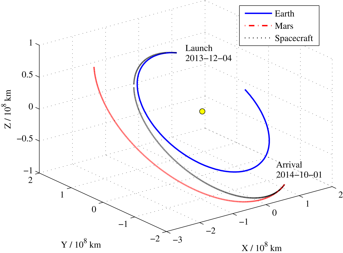
Figure 5. The transfer trajectory from the Earth to Mars in the heliocentric inertial coordinate system.
Table 2. Initial states of an Earth-Mars transfer orbit in the heliocentric inertial coordinate.

Figure 6 shows the distance from this transfer trajectory to EL 2 and ML 2. As shown in Figure 6, the configuration scheme mentioned in Section 3.1.1 can provide navigation information for the start and end of the cruising phase, which is significant so that a Mars probe can obtain an accurate insertion state.
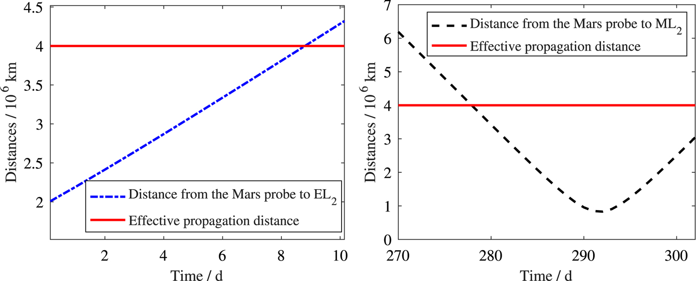
Figure 6. Distances from the Mars Probe to EL 2 and ML 2.
3.1.3. The autonomous navigation method applied for the host spacecraft
Realising high-accuracy autonomous navigation of the host spacecraft is the foundation to guarantee the positioning precision of the IoS. Hill (Reference Hill2007) proposed an autonomous navigation method in libration point orbits that only uses inter-satellite links. However, the convergence speed of this method for the Sun-Earth and Sun-Mars system is rather slow. X-ray pulsar navigation is a newly developed autonomous navigation method, which can provide high-accuracy absolute information for DSEs (Wang et al., Reference Wang, Zheng and Sun2014; Wang and Zheng, Reference Wang and Zheng2016). Thus, we apply x-ray pulsar-based relative navigation and inter-satellite links in this paper to realise autonomous navigation for host spacecraft. Their measurements are respectively the difference between the pulse time of arrivals and the distance of two spacecraft. Its specific principle can be found in Emadzadeh and Speyer (Reference Emadzadeh and Speyer2011). Table 3 shows the parameters of the chosen pulsars (Sheikh and Pines, Reference Sheikh and Pines2006; Sheikh et al., Reference Sheikh, Pines and Ray2006), and the x-ray background radiation flux is taken as 0·005 ph/cm2/s (Dennis, Reference Dennis2005). Table 4 shows the initial state of the Halo orbits around EL 2 and ML 2 in the synodic reference frame (Parker et al., Reference Parker, Anderson, Born, Fujimoto, Leonard and McGranaghan2006), where [L] and [T] are respectively the normalised units of length and time. The z-axis amplitude of the Halo orbit is 2 × 10⁵ km, and host spacecraft are distributed every equal phase. The initial state errors are respectively taken as 10 km and 10 m/s, the error of inter-satellite links is 1 m, and the observation period is 3,600 s.
Table 3. Parameters of chosen pulsars.

Table 4. Initial states of the Halo orbit around EL 2 and ML 2.

We apply an Unscented Kalman Filter (UKF) to investigate the performance of this navigation method. Figure 7 shows the position estimated errors and 3σ outlines of the host spacecraft around EL 2 and ML 2, and it can be seen that the positional accuracy can reach the order of 50 m.
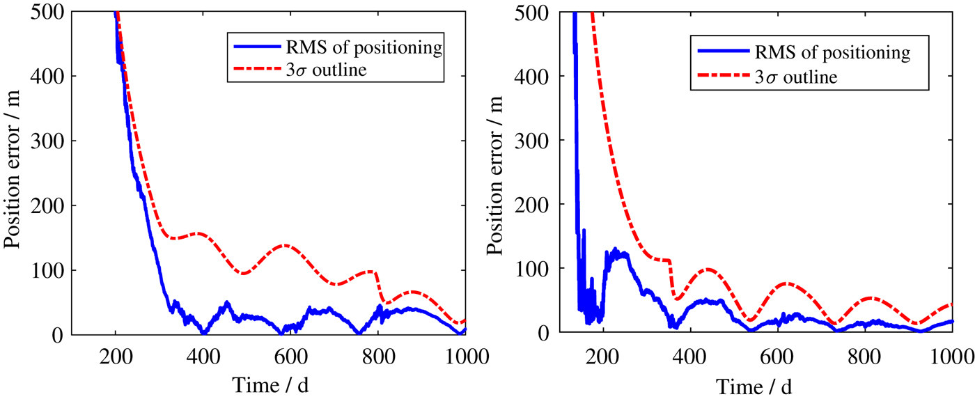
Figure 7. The position estimation error of host spacecraft around EL 2 and ML 2.
3.2. Navigation modes of client spacecraft
After the host spacecraft have determined their own positions, they can provide a navigation service for the client spacecraft, which only need to carry the inter-satellite ranging equipment. Note that when one client spacecraft has been positioned, its position can be transmitted to others in the form of a directional “request-response” mode.
With the increase of the rate of space missions, the IoS will be continuously expanded and improved. The subsequent spacecraft can program the communication links according to their own requirements and choose one or several nearby spacecraft from the IoS to realise their own autonomous navigation.
Combining the designed scheme of the reference of the IoS in Section 3.1, navigation modes of the client spacecraft are analysed. Figure 8 shows different navigation modes of the Mars probe at different phases, which have been mentioned in Section 2. A, B and C are host spacecraft at the Halo orbit around EL 2. D, E and F are the reference around ML 2 and the spacecraft G is the Mars probe whose communication links have been programmed, H is another client spacecraft that is within the communication scope of G, and I is a Mars Orbiter that can provide navigation information to others.
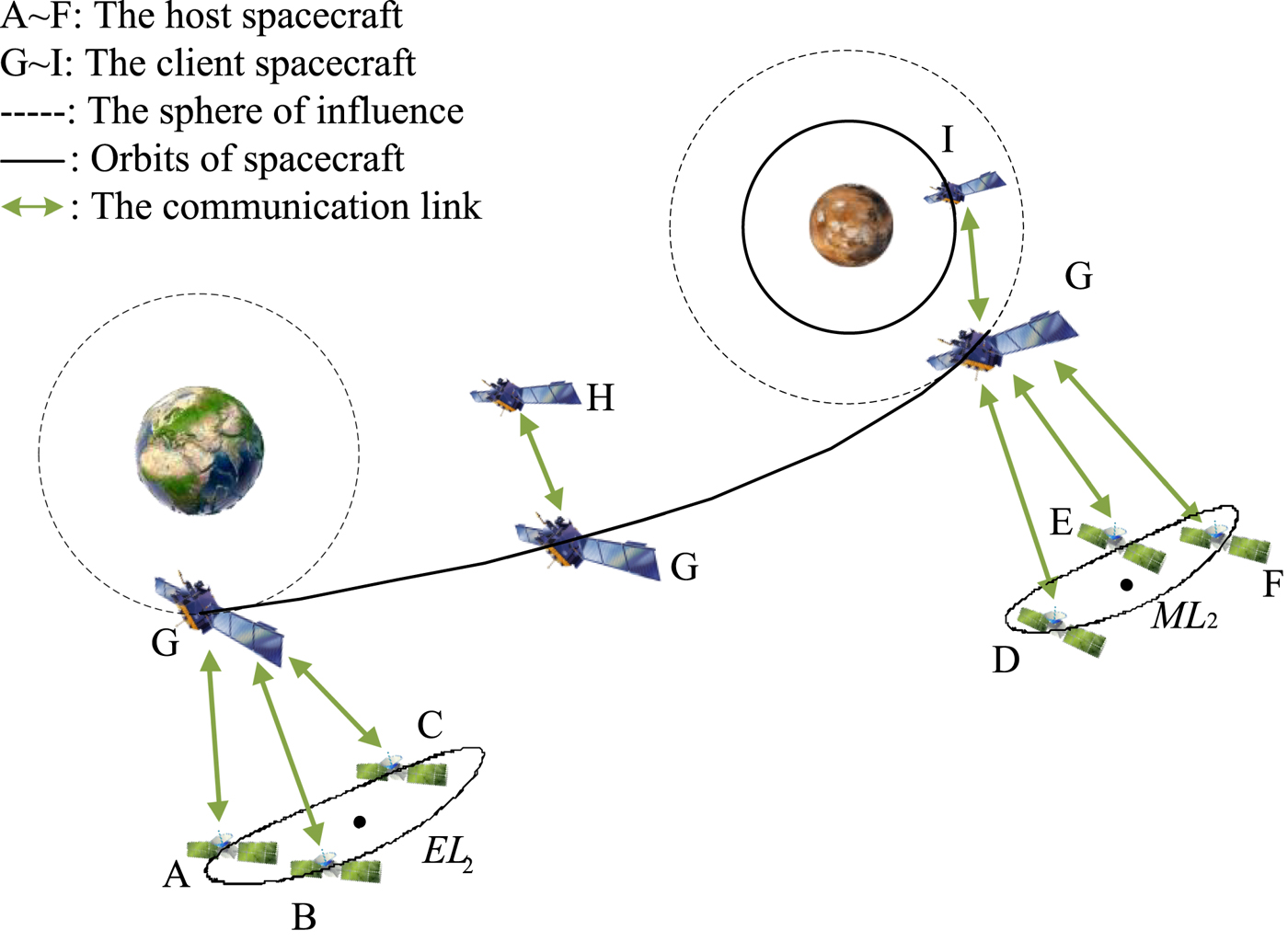
Figure 8. Schematic of the client spacecraft's navigation modes in the IoS system that can support a flight from the Earth to Mars.
The Mars probe G can choose different host spacecraft or client spacecraft at different flight phases. Three different cases are designed to investigate the performance of the corresponding navigation modes.
Case 1: The spacecraft G is located at the initial stage of the cruising phase and can be covered by the host spacecraft. Therefore, it can choose the host spacecraft around EL 2 as the communication target.
The initial states of G in this case are the same as those in Table 2, and its position and velocity errors are respectively 10 km and 10 m/s. The navigation interval is 3,600 s, and the error of inter-satellite links is taken as 50 m considering the position error of host spacecraft which was analysed in Section 3.1.3. Figure 9 shows the result of the UKF and the 3σ outlines. It can be seen that the position error can converge within six days and reach a precision of about 1 km. Therefore, the Mars probe can insert into the cruising phase with smaller state errors.
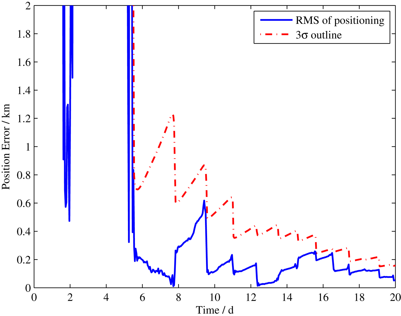
Figure 9. The position error of the client spacecraft for Case 1.
Case 2: The spacecraft G's flight segment is still the cruising phase, but it cannot receive the signal of a host spacecraft in this scheme. It could choose another client spacecraft (the spacecraft H in Figure 9) within its communication scope to modify its state. Table 5 shows the initial states of G and H of this case. The simulation conditions are taken as the same as that in Case 1. The positioning result is shown in Figure 10, which can reach an accuracy of 40 km (3σ).
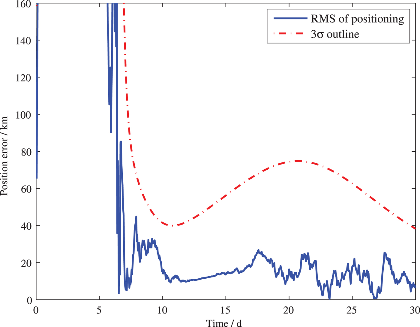
Figure 10. The positioning error of the client spacecraft for Case 2.
Table 5. Initial states of the spacecraft G and H in the heliocentric inertial coordinate system.

Case 3: The client spacecraft G has inserted into Mars' sphere of influence and the host spacecraft around ML 2 and a Mars Orbiter (the spacecraft I in Figure 8) are chosen to provide the navigation service. Table 6 shows the orbit elements of the Mars probe G and the Orbiter I, the position errors and velocity errors are taken as 1 km and 1 m/s. The other simulation conditions are the same as those in Case 1. Figure 11 shows the results of this case, and the position errors are within 500 m.
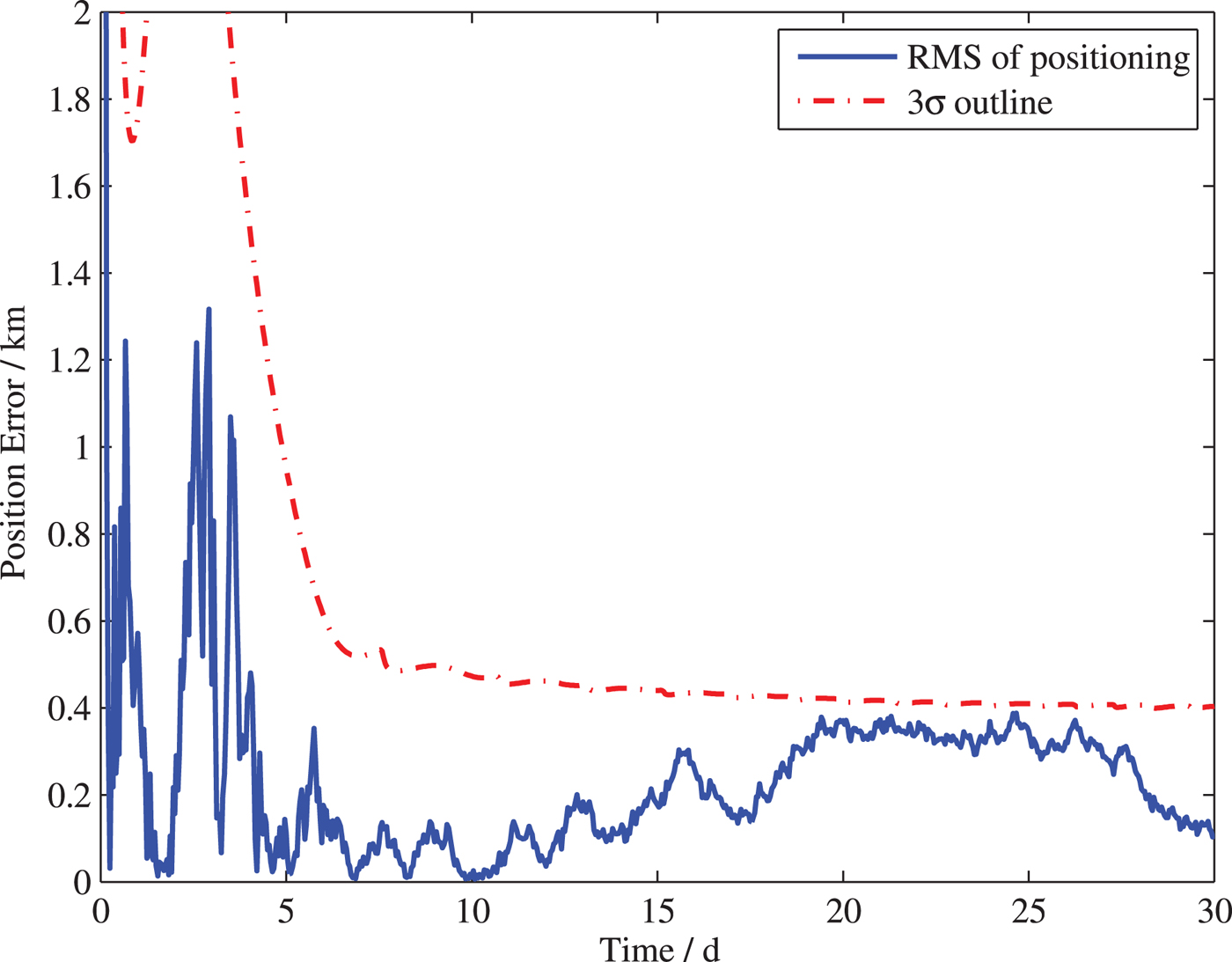
Figure 11. The position error of the client spacecraft for Case 3.
Table 6. Orbit elements of the client spacecraft that are near Mars (Lightsey et al., Reference Lightsey, Mogensen, Burkhart, Ely and Duncan2008).

The above three cases represent three different navigation and communication modes of the client spacecraft of the IoS. Our results show that the IoS could provide a high-accuracy navigation service for a Mars Probe during its whole flight. Furthermore, this continuously updated network can play an important role for missions to Mars as well as other deep space exploration missions.
4. CONCLUSIONS
An interplanetary space-based autonomous navigation network named the Internet of Space (IoS) is proposed in this paper. This network is composed of two parts, host spacecraft and client spacecraft. The former forms the absolute reference of the IoS, and the latter has installed an identical inter-satellite ranging device to communicate with other spacecraft through a “request-response” mode.
To describe the IoS in more detail, a specific application scheme supporting a flight from the Earth to Mars was developed and analysed. The Halo orbits around EL 2 and ML 2 are chosen for host spacecraft and the feasibility of this scheme was verified by analysing the signal intensity of the reference. Our results show that if the navigation information is transmitted in the form of electromagnetic waves, and the development of science and technology is taken into account, the effective navigation distance can reach 4 × 10⁶ kilometres, which can cover the initial and end stage of the cruising phase for a Mars mission. X-ray pulsar-based navigation using time-differenced measurement and inter-satellite links are applied to navigation for the reference and its positioning accuracy can reach around 50 m. Three navigation modes of the client spacecraft were programmed according to the different navigation distances for different flight phases. Results show that a Mars probe can obtain high accuracy autonomous navigation information for the whole flight.
As the number of deep space exploration missions increases, an IoS would be continually expanded and upgraded to provide more abundant navigation information and could eventually be expected to cover the whole Solar System.
ACKNOWLEDGMENTS
The work was supported by the Natural Science Foundation of China (No. 61703413).


