NOMENCLATURE
- b
-
wingspan
- AR
-
aspect ratio
- [A]
-
state matrix
- [B]
-
input matrix
- {u}
-
input vector
- {x}
-
state vector
Subscripts
- F
-
flexible vehicle dynamics
- R
-
rigid vehicle dynamics
Abbreviations
- 6DOF
-
six degrees of freedom
- ABFF
-
anti-symmetric body freedom flutter
- AEI
-
aerodynamic efficiency improvement
- AFRL
-
Air Force Research Laboratory
- AW1B
-
anti-symmetric wing first bending
- AW1T
-
anti-symmetric wing first torsion
- AWBT
-
anti-symmetric wing bending torsion
- BFF
-
body freedom flutter
- FCS
-
flight control system
- GCS
-
ground control station
- GVT
-
ground vibration test
- HALE
-
high-altitude long endurance
- IFAC
-
integrated flight and aeroelastic control
- IRAD
-
independent research and development
- LCO
-
limit cycle oscillation
- LM
-
Lockheed Martin Corporation
- LM Aero
-
Lockheed Martin Aeronautics Company
- MAD
-
multi-utility aeroelastic demonstrator
- MFMC
-
multiple flutter mode control
- MUTT
-
multi-utility technology test-bed
- NASA
-
National Aeronautics and Space Administration
- NDOF
-
number (normally greater than six) degrees of freedom
- RFC
-
rigid flex coupled
- SCT
-
structural coupling test
- SM
-
static margin
- SW1T
-
symmetric wing first torsion
- SWBT
-
symmetric wing bending torsion
- UAV
-
unmanned aerial vehicle
- VFG
-
velocity, frequency, and damping
- X-56A
-
A Lockheed Martin designed and built research aircraft
1.0 INTRODUCTION
The X-56A is a Multi-Utility Technology Test-bed (MUTT) designed by Lockheed Martin to perform high-risk flight tests under contract to the Air Force Research Laboratory (AFRL). Figure 1 shows a photograph of the aircraft just after take-off on its first flight. The initial technology demonstration of the aircraft is to further research the Rigid Flex Coupling (RFC) phenomenon and to continue development of Integrated Flight and Aeroelastic Control (IFAC). The ground work for IFAC on the X-56A was accomplished by demonstrating Multiple Flutter Mode Control (MFMC) in the Body Freedom Flutter (BFF) program(Reference Holm-Hansen, Atkinson, Beranek, Burnett, Nicolai and Youssef3). Current passive methods of dealing with these aeroelastic issues come at the expense of performance through increased structural weight, configuration changes and/or a reduced flight envelope. The IFAC system to be demonstrated on the X-56A simultaneously controls the flight dynamics and stabilizes multiple flutter modes as part of the Multi-utility Aeroelastic Demonstrator (MAD) program. The Flight Control System (FCS) uses advanced feedback control to allow the flight control surfaces to add damping to the unstable structural modes.

Figure 1. X-56A's first flight at NASA Armstrong (formally Dryden) Flight Research Center on 26 July 2013 (photo NASA/AFRL).
This paper presents a short history of previous active flutter suppression work and the path that led to the development of the X-56A aircraft. The paper then presents details on the X-56A MUTT research system. A discussion of the IFAC system development, including MFMC, is followed by some of the lessons learned in the development and testing of the X-56A research system. The paper concludes with a summary of the work done to date and a conclusion with recommended additional work.
2.0 HISTORY
Aeroelastic instabilities, both divergence and flutter, have been addressed for many decades primarily through passive means via structural and/or configuration changes and modifications to the flight envelope of aircraft. Typically, the design process is to engineer for sufficient strength to carry aircraft loads, and then analyse and re-engineer for aeroelastic stability if required. The need for vehicle performance improvement has created a commensurate need for more unconventional aircraft configurations. An example of such a configuration is the high aspect ratio flying wing. Unfortunately, the performance increase is accompanied by a phenomenon that can prevent the vehicle from becoming reality. This is RFC, which is defined as the dynamic coupling of a rigid body mode such as the short period with a primary flexible mode such as wing symmetric first bending. This coupling is a result of the frequencies of these modes, their shapes and unsteady aerodynamics. This behaviour leads to the rigid body dynamics being strongly coupled to the flexible dynamics due to the vehicle configuration.
Stability of such a configuration can be greatly affected through the introduction of an FCS. The intent of the FCS is to achieve desired flying qualities of the vehicle. This may be in the form of improving rigid body dynamics or actually stabilizing an unstable rigid body mode. But for the RFC-type vehicle, stability augmentation also greatly changes the vehicle's flexible dynamics due to the inherent coupling between the rigid body and flexible modes. Typical FCS design utilizes a six-degrees-of-freedom (6DOF) model that ignores the flexible dynamic coupling. Use of such an FCS often results in degraded flying qualities or the strong possibility of system instability. Ultimately, a 6DOF model is inappropriate for FCS design of an RFC type vehicle because dominant dynamics are missing from the equations of motion.
The Venn diagram presented in Fig. 2 can be useful to help understand the nature of RFC. A typical fighter-type aircraft has minimal coupling between rigid and flexible modes. The coupling effects can be expressed as static “flex to rigid ratios” applied to the 6DOF aerodynamics database. Dynamically, the coupling effects can be mitigated by applying notch filters to control paths based on frequency responses derived from analysis and structural coupling testing. The second Venn diagram represents non-critically coupled aircraft. The Lockheed Martin DarkStar and PoleCat are both examples of this level of RFC interaction. At this level of coupling, the flight controls must be designed to account for the flexibility of the aircraft even though there are no open-loop structural instabilities within the flight envelope. However, there is a very good possibility of closed-loop structural instability if the flight controls are designed solely with a 6DOF model. The last Venn diagram is the critically coupled condition. In this case, flexible mode instabilities lie within the flight envelope. This is the case of the X-56A and the proposed SensorCraft vehicles. The flight controls must explicitly account for the coupled rigid-body/flexible-vehicle dynamics where flexible mode suppression is now required. If this approach is not used, then structural, configuration and/or envelope changes will be required. These often have led to the inability to achieve vehicle performance goals.
Figure 2. Rigid flex coupling Venn diagram of criticality.
Over the last 5 decades, these RFC issues have become more prevalent. Figure 3 is a time line of the programs within Lockheed Martin Aeronautics Company (LM Aero) that have had to deal with RFC issues and the pace of technologies in the form of Technology Readiness Levels of a solution. Not shown in the figure is the number of new programs affected by RFC that must deal with critical RFC issues.

Figure 3. Increase in programs dealing with flutter issues as the desire for performance increases.
DarkStar, PoleCat and the X-56A are all examples of RFC in high aspect ratio, low tail volume configurations. However, RFC is not limited to high aspect ratio designs. High-speed configurations that rely on high fineness ratios also exhibit coupling. RFC in this configuration generally is the short period coupling with the fuselage first symmetric bending mode. This results in a porpoising motion of the vehicle in flight. Figure 4 shows several programs that have had to deal with RFC issues.

Figure 4. Rigid/flex coupling affects high fineness ratio and high aspect ratio low tail volume vehicles.
Active flutter suppression has been considered by many organizations for several decades, and research dates back to the late 1960s and early 1970s. A flutter mode control was demonstrated on a B-52 aircraft modified for use in the Control Configured Vehicle program. The system used aileron and flaperon control surfaces to stabilize a symmetric wing flutter mechanism. The flutter suppression system demonstration included flight to 12 Kn above the open-loop flutter speed(Reference Roger, Hodges and Felt4). The conclusion of this effort was that active flutter suppression was within the capability of the analytical methods of that time.
In the mid-1970s, a program was developed to investigate the possibility of suppressing stores flutter on an F-4F aircraft. The program was a joint effort of the German Ministry of Defense and the United States Air Force(Reference Sensburg, Honlinger, Noll and Huttsell5). Wing stores exhibited limit cycle flutter within the flight envelope due to the combination of store pitch inertia, pylon pitch stiffness and backlash/preload in the pylon system. Suppression at subcritical speeds of a specific pitch mode was demonstrated.
The 1970s also saw the application of gust load alleviation on the Lockheed L-1011 to increase aircraft life by reducing the amplitude of gust-induced loads. This system was flight demonstrated but was not put into production use(Reference Guinn, Rising and Walt6,Reference O'Connell7) .
Also during the L-1011 gust load alleviation effort, a flutter margin augmentation system was developed and demonstrated. This was utilized to increase the damping in a wing/engine mode. Flight demonstration showed as high as a 118% improvement in damping but was lower than predicted. Again, this system was not put into production(Reference O'Connell and Messina8).
In this same time period, the B-1 bomber was equipped with a Structural Mode Control System to reduce the forward fuselage loads and to improve ride quality for the crew during low-altitude missions. These systems were independent of the primary FCS and were not flight critical(Reference Wykes, Mori and Borland9,Reference Wykes, Byar, MacMiller and Greek10) .
Flight test of the B-2 bomber in the 1990s uncovered a reduction in pitch stability during low-altitude high-speed penetration missions. The phenomenon was dubbed a “residual pitch oscillation” and was determined to be caused by transonic shock wave movement on the body coupling with the aircraft's FCS and first wing bending mode. In many ways, this phenomenon is an example of RFC and is similar to a limit cycle oscillation of BFF. This residual pitch oscillation resulted in mission limitations being placed on the aircraft(Reference Jacobson, Britt, Freim and Kelly11,Reference Britt, Jacobson and Arthurs12) .
AFRL sponsored the Aerodynamic Efficiency Improvement (AEI) study as part of the larger SensorCraft program. The AEI program utilized semi-span wind-tunnel flutter models to examine RFC behaviour such as BFF(Reference Love, Zink, Wieselmann and Youngren13). These studies were valuable; however, great care and expense were required to account for the wind-tunnel model structural dynamics and the wind-tunnel mounting system. A pitch and plunge apparatus was utilized to emulate centreline symmetric motion of the half-span model. Parts of the aeroelastic community feel that pitch and plunge mounts and constrained flight wind-tunnel models all suffer from wind-tunnel effects that differ from true free flight.
In 2005, LM Aero began an Independent Research and Development (IRAD) program to validate aeroelastic modelling techniques, to integrate the flutter and flight controls community, and to investigate active flutter suppression concepts. This IRAD was originally focussed on the RFC phenomenon up to the first unstable structural mode the vehicle was expected to encounter, BFF. The concept of the research was to build low-cost expendable vehicles for testing so that flight tests could be taken all the way to instability(Reference Burnett, Atkinson, Beranek, Sibbitt, Holm-Hansen and Nicolai14). A photograph of a BFF aircraft experiencing BFF is presented in Fig. 5.
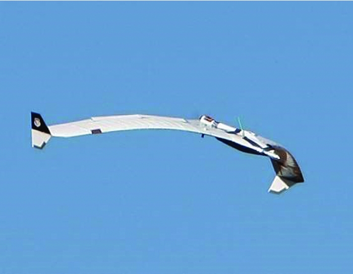
Figure 5. The BFF aircraft shown well into undamped RFC.
During the BFF IRAD and the subsequent contractual research and development project, it became apparent that the technology needed was a complete solution to the RFC which included the stabilization of the rigid body vehicle combined with the stabilization of the unstable flexible mode. The active flutter suppression work of the 1970s and 1980s treated the rigid vehicle dynamics independently from the flexible. The work of the 1990s and 2000s focused on non-critical RFC of vehicles such as DarkStar and PoleCat. It is now time to focus on the technologies needed to deal with the critically RFC aircraft.
IFAC is not just about structural stability. The aeroelastic nature of the airframe can also be used to increase manoeuvrability. A modified NASA F-18 re-designated the X-53 used wing flexibility for the development of control power. Specially modified leading-edge flap surfaces were used in conjunction with the aircraft's ailerons and trailing-edge flaps and the wing's inherent flexibility to generate rolling moment(Reference Pendlton, Flick, Paul, Voracek, Reichenbach and Griffin15).
In 2009, the Air Force Research Laboratory (AFRL) issued a contract for a design study to explore the possibility of the development of a Multi Utility Technology Test-bed (MUTT) research aircraft that could be used for research that pertained to SensorCraft high-altitude long-endurance (HALE) aircraft(Reference Beranek, Nicolai, Buonanno, Burnett, Atkinson, Holm-Hansen and Flick16). AFRL desired a vehicle that could be used to investigate active flutter suppression and gust load alleviation as well as other research. Because much of the desired research would be at or beyond the vehicle's limits, it needed to be designed to be robust and recoverable. This study contract was the basis for the MAD program.
3.0 THE X-56A SYSTEM
The X-56A is a complete research system which includes two X-56A centre bodies and four sets of wings—one stiff set and three flexible flutter research wings. The system also includes a Ground Control Station (GCS) used to remotely pilot the vehicle and monitor flight test instrumentation. The GCS also includes flight simulation capabilities for training, and a system integration capability for hardware checkout. The X-56A features an open-architecture flight control computer, a modular expandable data acquisition system, an on-board power generation and distribution system, a flight test air data probe, ten flight control surfaces and a ballistic recovery parachute. The X-56A has open volume in the forward portion of the fuselage that can be used to house new sensors or other research equipment. The system is also designed to accommodate other possible configurations such as a joined wing. A structural hard point on the aft fuselage is available to accommodate the joined wing configuration or a third engine if it is ever needed. Figure 6 depicts the elements of the X-56A research system.
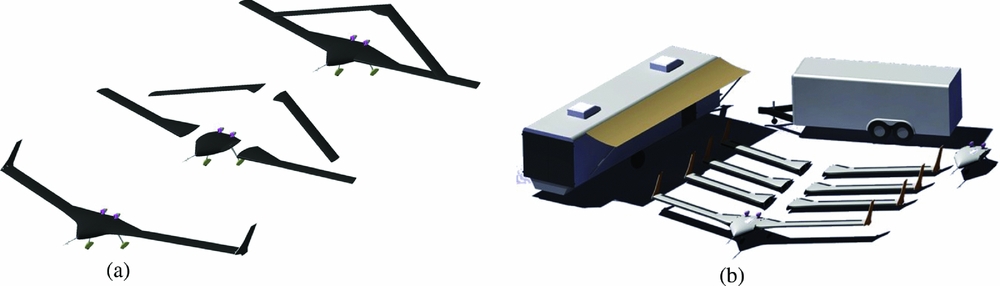
Figure 6. The X-56A is a complete research system.
The X-56A aircraft is a high aspect ratio (AR = 14) flying wing. The aircraft's span (b) is 28 feet and its maximum design take-off weight is 480 pounds. The aircraft is powered by two 80-pound thrust class JetCat P400 engines. A three-view drawing of the vehicle is presented in Fig. 7.

Figure 7. Three-view drawing of the X-56A aircraft.
The GCS was designed for ease of research. The pilots control the aircraft from a pilot station using flight path angle, bank angle, and airspeed commands with feedback provided by two heads-down displays and a heads-up display overlaid on a video from a forward-facing camera in the nose of the aircraft. The GCS also has two dual-screen flight test engineering data stations as well as support for a fibre-optic data link to the range safety facility. The GCS can be used as the training simulator for flight test rehearsals. A picture of the pilots’ station of the X-56A GCS is shown in Fig. 8.

Figure 8. Photo of pilot station in the X-56A GCS.
4.0 MODELLING, ANALYSIS AND VERIFICATION
The IFAC development of the MFMC was based on the design methods developed on the BFF IRAD program with the integration of the vehicle's rigid body dynamics. The X-56A is a non-critically coupled vehicle when equipped with the stiff wings and a critically coupled vehicle with the flex wings. For the flex wings, BFF was purposely placed within the flight envelope. Also, two other flutter mechanisms are on the edge of the flight envelope. These are symmetric wing first bending coupling with Symmetric Wing First Torsion which produces Symmetric Wing Bending/Torsion flutter (SWBT), and the rigid body roll mode coupling with anti-symmetric wing first bending and anti-symmetric wing 1st torsion which produces anti-symmetric body freedom flutter (ABFF). The controller must stabilize an unstable rigid body vehicle while simultaneously stabilizing BFF, SWBT and ABFF flutter. The control architecture of the stiff wing was purposely formed like that of the flex wing to best prove out the controller in the low-risk environment of the stiff wing prior to application to the flex wing.
Geometry and mass distribution are extremely important parameters in the aeroelastic behaviour of the aircraft. Detailed aeroelastic models of both vehicle configurations were developed as part of the design effort. This included careful modelling of both the mass and stiffness distribution throughout the design and build phases. Substantial effort was required to maintain configuration control of these models.
The aeroelastic models of the two aircraft configurations took the form of a rigid body/flexible vehicle coupled model. These included the rigid/flex coupling terms that produce the RFC behaviour. The form of the equation is presented in Equation (1). These state-space models were comprised of rigid body and flexible modal degrees of freedom and aerodynamic lag states resulting in approximately 400x400 state matrices to use for control law development. These large state space models are known as N Degrees of Freedom (NDOF) models, where the N in this case is 400 – the six standard states plus an additional 394 modal states representing the flexible aircraft and the coupling between the rigid vehicle dynamics and the flexible vehicle dynamics. Each of these NDOF models is only valid at a specific point in the envelope (velocity, altitude, mass and centre of gravity), so nearly 1,300 matrices made up the complete model of each aircraft.

Equation 1. State space equation for a rigid flex coupled aircraft
Roots of the state matrix were typically plotted in the form of velocity, frequency, damping plots or VFG plots. An example of a typical VFG plot for a flying-wing-configured aircraft is shown in Fig. 9. Items to note on the VFG plot are the coupling of the short period rigid body and the Symmetric Wing 1st Bending (SW1B). The coupling is indicated by the coalescence of the short period and wing bending frequency on the left plot and the rapid increase of damping in the short period and loss of damping in the wing bending mode in the plot on the right. The damping crossing corresponds to the BFF instability speed shown in the right plot. Also note the coupling of the SW1B with the Symmetric Wing 1st torsion (SW1T) mode, which results in Symmetric Wing Bending/Torsion (SWBT) flutter as shown in the damping plot. A third instability is also shown by the rigid body roll mode, coupling with the Anti-symmetric Wing 1st Bending (AW1B) mode and the Anti-symmetric Wing 1st Torsion (AW1T) mode, resulting in Anti-symmetric Body Freedom Flutter (ABFF). Another behaviour to note is the coupling of the AW1B mode and the AW1T mode, which results in the Anti-symmetric Wing Bending/Torsion (AWBT) hump mode. Finally, the VFG plot also shows the very-low-frequency rigid-body phugoid mode.

Figure 9. Typical velocity/frequency/damping plots of a flying-wing-type aircraft.
The same information contained in the VFG plot is also contained in a root locus plot. An example root locus plot is shown in Fig. 10. The fact that the same information can be shown in a way that is comfortable for the flutter engineer and the control law designer was important in bringing these different groups into a single team.
Figure 10. Root locus plot over an airspeed range.
The flutter state models were conditioned and further reduced where possible by the control law designers. These new models were used to design the initial paths and gains of the MFMC system for the stiff wing configured vehicle.
The ground test of the X-56A included a static load test, a control surface free-play test, a Ground Vibration Test (GVT) and a Structural Coupling Test (SCT). The proof test validated the stiffness of the wings. Load cases for up-bending and down-bending were conducted. Free-play tests were conducted on each control surface. A typical free-play result is shown in Fig. 11. The control surfaces and actuators showed good stiffness and low backlash characteristics.

Figure 11. Typical control surface free-play test results.
The GVT was conducted with the vehicle suspended on bungee cords. The aircraft was fitted with external accelerometers and was excited with external electromagnetic shakers. Data from this test was used to correlate the structural dynamic model. While the external accelerometers were still attached to the aircraft, a “mini-GVT” was conducted. The mini-GVT was very much like an SCT in that the excitation was generated by sine sweeps of the control surfaces. The mini-GVT along with the results from the complete GVT were useful in calibrating the on-board instrumentation and to establish a more economical method of conducting a mini-GVT for future configurations without the need for a complete GVT.
A full SCT was also conducted to identify any gain and phase issues of the flight control sensors. All of these ground tests were used to provide correlation information for the structural dynamics model prior to the start of the flight test of the aircraft.
The flight testing included system checkout and calibration test-points using the stiff wing configuration. The stiff wing flights were also used to provide additional correlation of the structural dynamics model and the doublet lattice method unsteady aerodynamic model.
These correlated models are the foundation of the MFMC FCS for the flex wing aircraft. In the case of aircraft that have critically coupled rigid body modes and structural modes, the flight controls and flutter suppression systems must be designed in unison. The vehicle must have adequate flutter margin and must preserve the flying qualities for the pilots and the on-board sensors.
The final portion of the flight test program will be performed using the flexible wing configuration and devoted to envelope expansion using the MFMC system. Unfortunately, flight tests that were to be conducted in the spring of 2014 have been delayed due to technical findings in the development of the control system and the manner in which it is tested. However, a path forward has been identified and results from this flight test program will be presented at the completion of the campaign.
One major issue to overcome with the development of IFAC and especially MFMC is acceptance. Just as with the first fly-by-wire aircraft that were open-loop unstable, it will take a significant amount of flight research and demonstrations before the control of unstable structural modes within the flight envelope becomes common. It will take demonstrations of both system reliability as well as the increased performance made possible by such a system. This will no doubt be a slow process as it was with the development of fly-by-wire control systems that enabled the performance benefits of statically unstable aircraft to become commonplace. The new IFAC technology will first be used to increase margins to allow for the increase of an aircraft's flight envelope much as stability and control augmentation systems allowed for relaxed static margins, which allowed both performance and agility increases. If we wish for a future that includes aircraft that fly higher, further and faster and are more affordable, we must continue to perform the flight research and conduct the flight demonstrations of MFMC.
5.0 LESSONS LEARNED
There were several lessons learned in the design and testing of the X-56A system.
The standard process of designing for strength and analysing for sufficient stiffness was challenged. The design of the X-56A required that the aircraft have a specific stiffness and mass distribution in the flexible wing sets to achieve the desired aeroelastic behaviour. The stiff and flex wings share a common carbon fibre spar and rib design. Material selection proved to be a challenge as the outer mould line of the stiff and flex wings are the same and the internal ribs and spars are common, so the stiffness variation is limited to the wing skins. The stiff wing has a carbon fibre skin with a large number of uni-directional plies in specific locations and orientations to ensure no flutter modes are present in the flight envelope. The flexible wings are fabricated of four plies of fibreglass and foam sandwich construction. To obtain the desired behaviour, not only are the bending properties important, but also the shear properties. The fibreglass plies were laid in a 0/90 orientation to minimize shear stiffness. Testing late in the program revealed that the shear modulus of this ply layup was resin-dominated, not fibre-dominated. This resulted in a torsional stiffness that was approximately 30% higher than predicted.
The X-56A aircraft is designed such that in the event of an in-flight structural failure, the high-value electronics and systems located in the centre body of the aircraft can be recovered. The vehicle was designed with a ballistic recovery system parachute to control the rate of decent. The team also looked at methods to further improve the probability of recovery through removal of the wings via explosive bolts or shear pins. In all cases, the cost of the device or the cost of other safety implications made the use of such devices cost prohibitive. The fact that the wings may be in an unknown “broken” configuration did drive some of the structural design load cases for the parachute system and in turn increased the overall weight.
Flight controls actuation was identified as a risk item at the beginning of the program. The size of the X-56A limits the possible choices for actuation. The hobby servos are too small and most of the certified aircraft servos are too large and very expensive. The nature of MFMC required that the servos be small, high torque, high bandwidth and low acklash. Several commercial robotic servos were tested in the laboratory. However, none met the program requirements. The program finally decided on a harmonic drive actuator coupled with a customized feedback controller and output position sensor(Reference Holm-Hansen, Burnett, Beranek, Atkinson, Kuchinsky and Calhoun17,Reference Holm-Hansen, Beranek, Burnett and Atkinson18) . Once the feedback gains were tuned, this combination proved to be well suited to the program's needs, and it fit into the wing with a millimetre or two to spare. A Bode plot of the servo systems is presented in Fig. 12.
Figure 12. Typical Bode plot of the X-56A flight control surface servo.
Loads testing, GVT and a SCT were used for verification of our aeroelastic models. All of these tests showed good correlation between the aircraft and the design models. However, because of the low frequency of some of the structural modes, issues with the suspension system used for the GVT were found. Correlation of the X-56A to GVT required that the suspension system be modelled. Future GVT efforts must implement lower-frequency suspension systems or continue to model the system for correlation purposes.
As the MFMC was being designed, it became clear that some of the assumptions used in the formulation of the linear aeroelastic model needed to be refined. Because the aeroelastic model is being used as the basis for the rigid-body outer loop feedback as well as the inner-loop flexible, this is especially true. Several assumptions that affected the apparent gain of the system at low frequency needed to be removed. Most influential was the inclusion of the phugoid mode. Figure 13 shows a typical Bode plot of the vehicle pitch rate due to a control surface deflection for the rigid 6DOF model, the NDOF model with the original assumptions, the NDOF with the phugoid and no flexible modes and the NDOF model after the assumptions were removed.
Figure 13. Pitch rate due to control surface Bode plot comparison between 6DOF and NDOF.
Once a controller has been designed, it must be tested. For most aircraft, a simple static flex to rigid ratio included in the aerodynamics of the 6DOF real-time simulator is adequate for verifying that the control system reacts as designed to sensor inputs. In the RFC aircraft case where the controller has been designed around a flexible structure, this is no longer adequate. Changes in frequency of the short period and gain peaking due to first wing bending must be accounted for. Therefore, to test a MFMC controller with pilot or hardware in the loop, a real-time NDOF model that can provide the correct magnitude and phase of a structurally mounted sensor is needed. For functional acceptance testing, failure modes and effects testing, and pilot evaluation, training and flight test rehearsals, a model that is capable of covering the entire flight envelope is desired.
The X-56A will continue as a flying test-bed and research platform as a part of the fixed-wing flight research program at NASA Armstrong Flight Research Center. NASA as well as several other aerospace companies have started work on new wing and/or controller designs for the X-56A. NASA also plans to use the vehicle to examine other aspects of the control of extremely flexible, high aspect ratio wings and lightweight structures. These areas of research include improvements in modelling techniques, new sensor technologies, new control effectors, real-time drag optimization, and feedback control methods and architectures.
The X-56A aircraft will continue to provide a low-cost means to perform flight research in the future. It has been said that the true value of flight research is the discovery of what you did not know to study.
We hope the future will see a continuation of this research to explore the benefits that IFAC can bring to high-speed aircraft. In particular, we hope to demonstrate the performance benefits that can be achieved by simultaneously controlling rigid body flight dynamics and BFF on high-fineness-ratio vehicles. It is our hope that this supersonic vehicle will be designed to perform additional flight research as well as flutter suppression, possibly a ‘Super MUTT’.
6.0 CONCLUSION
The development and initial flight research of the X-56A have already led to much greater understanding of RFC issues.
The requirements for the testing of the X-56A required that the structural design provide not only strength but also a specific stiffness to set the flutter speeds at specific points in the flight envelope. Future designs that will rely on MFMC will only require strength, and the stiffness will be a fallout of the design because the damping will be provided by the feedback control system.
As the program attempted to control the modal behaviour of the flexible wings, the shear stiffness was not analysed for the specific ply orientation. It is important to remember that in order to lower the weight of future structures, the material properties must be analysed for the specific application including ply layup.
The design of a system that is meant to research new technologies will by its very nature have many unknowns. This is often where the greatest value of the research is realized. However it is easy to cause other issues in the process of trying to mitigate one risk. In the case of the X-56A with an unknown “broken” configuration, the structural design increased in weight. Early acceptance of these risks may result in a more capable system or a different mitigation altogether.
Structural mode control requires an actuation system with high bandwidth and load capability. Medium-sized Unmanned Aerial Vehicles (UAVs) have few actuation choices. It is important to not overlook something like actuation in the design of a new vehicle especially if the vehicle has any special requirements such as bandwidth or size.
The ground test of vehicles with relaxed structural stiffness requires special test equipment. Be very aware of the possibility that the ground test set-up may be influencing the tests results and the test setup itself may need to be analysed.
The testing and certification of future aircraft that have reduced structural stability, and especially ones that rely on MFMC, will require new modelling and simulation techniques to provide the necessary testing and training environment. New real-time NDOF models that can stimulate the structural mounted sensor must be invented and proven.
Through the lessons learned in the development and testing of the X-56A, we have a better understanding of what will be required to field new unique aircraft configurations that require IFAC and MFMC to fly higher, farther, faster and cheaper.
ACKNOWLEDGEMENTS
Support for this program was provided by the Air Force Research Laboratory. Additionally, the authors would like to thank NASA Armstrong Flight Research Center for their efforts in supporting the flight test of the X-56A MAD MUTT.