


1. INTRODUCTION
The General Lighthouse Authorities (GLAs) of the UK and Ireland have been involved in Loran for a number of years. The UK was officially classed as an observer in the Northwest European LORAN-C System (NELS) agreement, which came to a close at the end of 2005, and representatives of the GLAs were on several working groups of that organisation. Nowadays, the GLAs are playing an increasingly active role having run a Loran station at Rugby in the UK since July 2005, and recently moving the transmitter to Anthorn in Cumbria. It is the aim to provide the service, contracted with VT Communication, until at least 2022. This reinforces the GLAs' conviction that the future Loran, eLoran, is the only dissimilar, multi-modal source of position, navigation and time (PNT) that is independent from, and hence mitigates e-Navigation risks associated with, GNSS. eLoran is seen by the GLAs as a core component of e-Navigation.
2. e-NAVIGATION
e-Navigation is currently defined by IALA as:
The harmonised collection, integration, exchange, presentation and analysis of maritime information onboard and ashore by electronic means to enhance berth to berth navigation and related services, for safety and security at sea and protection of the marine environment.
That definition covers the infrastructure required to ensure safe, efficient and cost effective maritime transport: positioning, navigation, timing and communications.
2.1. The Components of e-Navigation
e-Navigation will contain a number of components
• Accurate, comprehensive and up-to-date electronic navigation charts
• Accurate and reliable electronic positioning signals
• Information on a vessel's route, bearing, manoeuvring parameters and other status items, in electronic format
• Electronic Chart Display and Information System (ECDIS) for clear, integrated display of information
• Transmission of positional and navigational information from ship-to-shore, shore-to-ship and ship-to-ship, using the AIS
• Information prioritisation and alert capability in risk situations on ship and ashore.
2.2. Benefits
The benefits of e-Navigation include the possibility of new applications to meet emerging and future requirements for marine navigation. In the example of Figure 1 a wreck is immediately marked by one or more virtual aids to navigation (AtoN). This gives a timely warning of the problem on bridge displays. Meanwhile, a buoy tender is dispatched to mark the site with physical wreck marking buoys. Integrated Bridge Systems will bring all of these e-Navigation components together in a convenient package, easily accessible, understandable, efficient and cost effective, enabling one and two man bridges while reducing the capacity for human error.

Figure 1. e-Navigation will enable new applications such as virtual AtoNs for timely wreck marking.
e-Navigation has the potential to allow cost savings brought about by the rationalisation (the reduction not the elimination) of the number of physical aids that require expensive maintenance; expenses that include ship time and associated fuel costs. However, visual aids will always be needed by e-Navigation to provide a reversionary capability and the GLAs have an extensive programme of work on such visual aids [Reference Nicholson1].
2.3. Service Provision Environment
e-Navigation is an important step forward for the mariner. Ships are getting larger and faster, traffic densities are increasing. The Dover Straits handles 500 vessels a day. Hub and spoke operations, while being efficient commercially, multiply the number of vessels requiring access to individual ports. In addition, fixed offshore structures like windfarms all need their presence to be known. Because of inherent alert capabilities e-Navigation will make running one and two man bridges safer by helping to compensate for a false sense of security around electronic aids. As already mentioned, physical aids will always be needed, but reverting to those aids from the relative comfort of electronic navigation will become more and more difficult as mariners lose the skills necessary to use conventional means. This could possibly result in worsened safety. A buffer system is therefore required between losing GNSS and reverting to physical aids.
3. GNSS
In e-Navigation GNSS will be the primary sensor, the mainstay for many years to come. With the addition of Galileo, GLONASS, and perhaps COMPASS and other systems there will be a high degree of availability for PNT solutions. GNSS will be used in AIS for position information and timing the system's data slots. GNSS will also be used in synchronised and sequenced lights to highlight channels and hazards at night, thus improving the conspicuity of such systems. GNSS is and will be everywhere.
3.1. Threats to the availability of GNSS
More and more people are becoming aware of the vulnerabilities of GPS. For example, the possibility of a terrorist attack on the GPS system is a reality. In April 2006 the FBI arrested two Atlanta men as part of a terrorism probe. Part of their plot was to disable the GPS system to disrupt military and commercial communications and traffic. There have been numerous outages of GPS over the years, caused by component failures:
• Atlantic Ocean, 28 July – 24 August 2000, lasting 27 days 6 hrs 53 minutes; the cause, an unstable satellite clock.
• Large portions of Europe, Africa, Asia, Australia and far North America, 1 January 2004, lasting 3 hours; a failed satellite clock.
• North America, 28 October 2002, lasting approximately 2 hours; an unstable satellite clock.
and there has been unintentional interference:
• In the early summer of 1996, repeated, apparently random failures of the DGPS receiver onboard the Manatoulin – a bulk carrier operating in the Great Lakes.
• In April 2001 the GPS signal in Moss Landing Harbour, around 100 km south of San Francisco, was jammed for a period of over a month.
Both of these latter incidents were caused by unintentional interference from active television receive-antennas. The GLA's ‘Case for eLoran’ document [2] contains more detail on these and other incidents.
It is not just GPS that is vulnerable; all of the GNSS share common failure modes being based in the same part of the radio spectrum with overlapping power spectral distributions, having very low power and being space based.
3.2. The Impact of the Loss of GNSS
High levels of availability and reliability of a PNT system are needed for e-Navigation, for all of the following reasons:
• Safety – may worsen because of a lack of familiarity when reverting from e-Navigation to physical AtoNs.
• Security – both AIS and Long-range Identification & Tracking rely on GPS for positioning and, to some extent, timing. Also on-board new technology radar does not have to trigger existing RACONS.
• Protection of the marine environment – e-Navigation virtual exclusion zones will not trigger alarms possibly leading to collisions and groundings.
• Economic – direct loss at Southampton port is £3m per day not including knock-on supply-chain costs. Oil spill clean-up costs are $11k/tonne. Exxon Valdez $2B cleanup+$5B fines. UK average cost is £8M per accident.
3.3. GNSS is Vulnerable
Table 1 shows vulnerabilities broken down by segment: system, signal and user. The different vulnerabilities are shown in the left hand column. The right hand column shows the possible mitigations. All but one calls for the need for a second dissimilar system.
Table 1. Vulnerabilities of GNSS and possible mitigations.

4. INERTIAL NAVIGATION SYSTEMS
One possible mitigation technique to tackle the vulnerabilities of GNSS may be to employ inertial navigation systems as the second dissimilar system. Such systems have several potential advantages and benefits.
They are ship based and independent of external systems, providing relative position data from a calibration point. They have the potential to provide an improved navigational solution, with position and velocity estimates available at a rapid update rate. They may also provide automatic warnings that other sensors, including GNSS, have failed or are giving reduced navigational accuracy. Finally, they may be able to maintain an acceptable navigation solution in the event of a failure or degradation of other sensors.
The GLAs commissioned the University of Nottingham to perform a study to assess the capabilities of inertial systems integrated with GNSS [Reference Hill, Hide and Norris3]. The study looked at the price and performance of commercially available Inertial Measurement Units (IMUs), so quantifying the accuracy of navigation in the event of a GNSS failure using different grades of IMU. Three devices were tested – classified as:
• Navigation Grade
• Tactical Grade
• Low Cost
The navigation grade IMU employed was the Honeywell CIMU costing £60,000, the tactical grade unit was a Honeywell HG1700 costing £14,000, while the low cost device was a Crossbow IMU300 MEMS (Micro Electro Mechanical System) based unit costing around £1,800.
4.1. INS Study Results
As can be expected with these units, the performance of each device was directly related to its cost. The results are shown in Table 2, which shows the time in minutes for the performance of each unit to degrade to below the performance requirements of each of the four maritime voyage phases; oceanic (open water), coastal and harbour approach. In a series of sea trials each IMU was initiated using one of two calibration systems; differential-GPS and Real Time Kinematic (RTK), with RTK providing the most accurate calibration.
Table 2. Performance of the IMUs used in the GLA study.

The GLAs are primarily interested in the coastal and harbour approach phases, and concentrating on the most accurate IMU, initially calibrated with RTK, the coastal navigation requirements are broken in just fifteen minutes. The harbour approach requirements are broken in just three and a half minutes! This indicates that these systems incur a very high price-performance ratio (at least with today's technology).
The main conclusion is that none of the options considered was suitable to maintain navigation accuracy during a major outage of GNSS. But what IMUs do allow is accurate navigation, for a defined period of time after a GNSS failure, to allow an orderly transition to an alternative technique.
5. THE CASE FOR eLORAN
We have seen that inertial systems are unable to serve as a second dissimilar system to act as a backup to GNSS in case of a failure. They have a potential role to serve, but with today's technology ship owners have to contend with the high price-performance ratio of such devices. The requirement for a second, independent input into systems that are totally reliant on electronic position fixing is fully consistent with best navigation practices as stated by the IMO. The GLAs' ‘Case for eLoran’ document [2] clearly states that eLoran is fully capable of acting as this second system and indeed it is needed both to ensure safety in a higher-risk environment and to deliver cost savings that result from the introduction of radionavigation services and their take-up in the maritime sector.
5.1. Loran Requirements
eLoran was born in the United States out of a need to investigate the potential for Loran-C to act as a complement and backup to GPS. In so doing the system would need to meet the future requirements of two major transport modes. The United States Coast Guard (USCG – the managers of the Loran-C system) acted for the maritime mode and the Federal Aviation Administration (FAA) for aviation. Their requirements for the Loran system are much more demanding than those of the old Loran-C as can be seen in Figure 2. The driver for the USCG was the ability of the system to meet their 8-20m (95%) accuracy requirement for harbour entrance and approach.

Figure 2. Current and future requirements of Loran. After [Reference Narins4]
On the other hand the FAA were driven towards the requirements for availability, integrity and continuity of the system for aviation. They also wanted to demonstrate Loran's ability to meet the Stratum 1 timing specification for telecommunications applications. In a US Government funded study led by the FAA, the group demonstrated ‘Loran's Capability to Mitigate the Impact of a GPS Outage on GPS Position, Navigation, and Time Applications’ [Reference Narins4], provided that certain conditions were met.
5.2. Modernising Towards eLoran
The study showed that provided certain actions were taken to update Loran-C in terms of equipment, performance and functionality, the new Loran, or eLoran, could meet their requirements. This set of modifications defines the system requirements for the new eLoran. For example, to meet harbour entrance and approach requirements, eLoran needs to include:
• differential-Loran (dLoran) and,
• Quality assured Additional Secondary Factor (ASF) data
ASFs are measured and disseminated for each SOLAS capable harbour. These are measured once and for all and are fixed within the users' receivers. To take into account seasonal and more short-term propagation changes, differential corrections are transmitted using the eLoran signal itself over a Loran Data Channel (LDC). See Figure 3. In the US the LDC is likely to be implemented by the 9th Pulse (and possibly 10th Pulse) system [5] [Reference Peterson6]. In Europe Eurofix is now installed on five stations as the LDC providing differential-GPS (and soon differential-Loran) corrections [7] [Reference Offermans8].

Figure 3. Differential-Loran, Eurofix and ASFs.
5.3. Maritime eLoran Performance
Three independent studies across the world have already demonstrated the ability of eLoran to meet the harbour entrance and approach accuracy specification. The results of these trials are shown in Figures 4 and 5. All three studies demonstrate sub-10m accuracy.
The results in Figure 4 are derived from post-processing, since a live dLoran system was not available at the time of the trial. The post-processing emulated the effects of dLoran. The results shown in Figure 5 come from a later trial where dLoran was run in real-time. These initial demonstrations show that not only can eLoran meet the USCG requirements, but that it can also meet the IMO A.915 accuracy requirements for Port Approach and Restricted Waters as illustrated by Figure 6. This means that eLoran is equivalent to L1 GPS or L1 Galileo Open Service.

Figure 4. Scatter plot of position error measured in Tampa Bay, (Left) and Harwich Harbour (Right) Post-processed results. After [Reference Pelgrum9]

Figure 5. Scatter plot of position error measured in the Thames River, CT. Real-time results. After [Reference Johnson, Dykstra, Oates, Swaszek and Hartnett11].

Figure 6. eLoran meets the IMO A.915 Port and Restricted Waters Requirement.
For maritime applications then eLoran fits the bill perfectly. The system is complementary to GNSS, as shown in Figure 7, and it can also serve as a stable and consistent backup.

Figure 7. eLoran is complementary to GNSS.
6. STEPS TOWARDS eLORAN IN EUROPE
The steps required to bring the current Loran up to eLoran standard are outlined in Figure 8. The United States eLoran programme is ahead of Europe in many ways. But in Europe Time of Emission control has already been implemented and all stations are solid-state transmitters, rather than the older tube type stations.
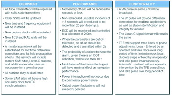
Figure 8. Work required to bring Loran up to eLoran standard. After [2].
The Eurofix Loran Data Channel is installed on five of those stations and there is finer control over system timing in Europe than in the US. The US has real-time differential-Loran up and running, and Europe will join it in 2008 when the GLAs install a prototype live differential-Loran service in Harwich, as part of their eLoran programme of work. There is a long way to go to bring European systems up to eLoran standard, but the process has already begun. Institutions such as the GLAs will monitor the US programme, which is now poised to move into an eLoran implementation phase.
Decisions need to be made. For example consider the Loran Data Channel; does Europe continue with Eurofix installation, or move to 9th Pulse? Can both systems be used at the same time? Is there enough bandwidth? How many new eLoran stations are required to ensure excellent European coverage and accuracy? How many dLoran reference stations are required? Where are these stations to be located?
The eventual publication of the ERNP, with eLoran included, will promote growth and commitment to eLoran in Europe. A European agreement needs to be reached in terms of:
• A concept of operations
• Interoperability and coordination of research and development work
• Funding
Efforts need to be coordinated, and IALA might have a role to play in this, based on their experience in setting up the Far East Radionavigation Service. Another consideration is the Eastern European Chayka system and whether that is to be updated and integrated into eLoran. And if so, how will that happen?
7. eLORAN DEFINITION AND THE STANDARDS PROCESS
The international eLoran standards process has begun. The process involves the following organisations: ILA, RTCM, ITU, IALA, IMO, IEC. Each will be considered below with opportunities for input to the various groups highlighted with reference to the timeline illustrated in Figure 9.

Figure 9. Timeline for the international standards process.
7.1. International Loran Association
The ILA has produced a top-level eLoran Definition Document. The other documents required to fully define the eLoran service are:
• Plan. To address policy, consider operational issues, present a service description and identify future developments. It may include a summary of user requirements that are met. An example of this type of document would be the US Federal Radionavigation Plan.
• Performance Specification. To define the level of performance including coverage that the service provider is committed to providing. It may take the form of a service level agreement. An example is the US GPS SPS Specification.
• Interface Control Document. To define the signal so that it can be accessed by user equipment. An example is the GPS ICD-GPS 200.
7.2. Radio Technical Commission for Maritime Services
The RTCM is responsible for signal and receiver specifications. The inaugural meeting of the RTCM Special Committee on eLoran (SC-127) took place in Orlando, Florida, on 15th October 2007. The group has resolved to standardise the formal eLoran signal and receiver specifications. Differential-Loran message types will also need to be standardized in the near future.
7.3. International Telecommunications Union
The ITU is responsible for signal technical characteristics and spectrum allocation. The Eurofix pulse position modulation scheme has already been standardised with the publication of ITU recommendation M.589-3, which provides technical characteristics for data transmission and interference protection. This may need revision and the addition of an annex giving more detail of the modulation systems. This will need to be prepared before the start of the 4th quarter of 2008 for ITU input.
7.4. International Association of Marine Aids to Navigation and Lighthouse Authorities
IALA is responsible for system operation and coordination and as an interface for input to ITU & IMO. Operational standards for eLoran could be developed by a working group of the IALA e-Navigation Committee, drawing on NELS, FERNS and USCG documentation. As can be seen in the timeline, IALA e-Navigation committees are due to meet in the first quarter of 2008 and 2009.
7.5. International Maritime Organization
IMO is responsible for performance standards and mandating carriage requirements. IMO Resolution A.818(19) contains performance standards based on long out-of-date technology. A new resolution is needed for consideration of the system to be a part of the World Wide Radio Navigation System (WWRNS). Input may be needed to the IMO's Maritime Safety Committee (MSC), whose next meeting is to be held in the second quarter of 2008, proposing that the subject is put on the IMO NAV sub-committee meeting agenda (NAV 54, 55 and 56 in the timeline). Alternatively, it could be dealt with under the e-Navigation task if eLoran is accepted as essential to it. The eventual aim is to make a submission to the IMO to class eLoran as a component of the WWRNS.
7.6. International Electrotechnical Commission
The IEC is responsible for equipment test specifications. IEC document 61075 ‘Loran-C receivers for ships’ is based on the old RTCM standard, and is not relevant to modern Loran. A new work item proposal is needed for that, ready for submission by the start of 2010.
8. SUMMARY AND CONCLUSIONS
e-Navigation will make safe navigation easier and cheaper. Electronic Position Navigation and Timing will underpin its navigation, situational awareness and communications functions. Two independent, complementary and multi-modal sources of position, navigation and timing are needed to realise the full benefits of e-Navigation. GNSS is undoubtedly the first, eLoran is the only option for the second.


