


1. INTRODUCTION
The rapid development of ultra-intense short-pulse laser technology since the invention of chirped pulse amplification has made it possible to study laser plasma interaction in the ultra relativistic regime (Häuser et al., Reference Häuser, Scheid and Hora1994; Hora, Reference Hora2000; Yu et al., Reference Yu, Yu, Chen, Zhang, Yin, Cao, Lu and Xu2003; Gibbon, Reference Gibbon2005; Hoffmann, Reference Hoffmann2008). It allows the basic research and applications of many novel relativistic plasma physics issues, ranging from compact particle sources (Hora, Reference Hora1988; Malka et al., Reference Malka, Faure, Gauduel, Lefebvre, Rousse and Phuoc2008; Zhou et al., 2008), to new light sources (Nakajima, Reference Nakajima2008), and fast ignition (FI) of inertial confinement fusion (Atzeni & Meyer-Tar-Vehn, Reference Atzeni and Meyer-Tar-Vehn2003), etc. In a cone-guided FI scheme, the deuterium-tritium (DT) fuel is first compressed to ultrahigh density by long-pulse lasers (Hora, Reference Hora2009; Kodama et al., Reference Kodama, Norreys, Mima, Dangor, Evans, Fujita, Kitagawa, Krushelnick, Miyakoshi, Miyanaga, Norimatsu, Rose, Shozaki, Shigemori, Sunahara, Tampo, Tanaka, Toyama, Yamanaka and Zepf2001; Tabak et al., Reference Tabak, Hammer, Glinsky, Kruer, Wilks, Woodworth, Campbell, Perry and Mason1994). Petawatt short laser pulses are then sent through a hollow gold cone attached to the fuel shell. The energetic MeV electrons produced from the laser-cone interaction are expected to ignite a small region inside the compressed fuel. Cone-guided FI reduces both the laser energy and precision requirements. However, this scheme has its own difficulities in collimating the energetic electrons inside the target. Because the beam current is about 1 GA, strong nonlinear interaction between the fast electron beam and the overdense plasma can lead to various microscope instabilities. It is difficult to maintain a convergent (focused) beam with r ig/r L < 1, where r ig and r L are the radii of the igniter beam and laser, respectively. Many experiments and simulations (Lancaster et al., Reference Lancaster, Green, Hey, Akli, Davies, Clarke, Freeman, Habara, Key, Kodama, Krushelnick, Murphy, Nakatsutsumi, Simpson, Stephens, Stoeckl, Yabuuchi, Zepf and Norreys2007; Green et al., Reference Green, Ovchinnikov, Evans, Akli, Azechi, Beg, Bellei, Freeman, Habara, Heathcote, Key, King, Lancaster, Lopes, Ma, Mackinnon, Markey, Mcphee, Najmudin, Nilson, Onofrei, Stephens, Takeda, Tanaka, Theobald, Tanimoto, Waugh, Wan Woerkom, Woolsey, Zepf, Davies and Norreys2008) show that fast electron flows are not well collimated in the cone-guided scheme. Therefore, collimation or focusing of the beam electrons is necessary.
To narrow the beam divergence, new target structures such as cones attached to a wire or funnel, wire targets with a nail-like head, a cannal in the extended tip of cone target, and two-layer target, etc., have been proposed (Green et al., Reference Green, Lancaster, Akli, Gregory, Beg, Chen, Clark, Freeman, Hawkes, Hernandez-Gomez, Habara, Heathcote, Hey, Highbarger, Key, Kodma, Krushelnick, Musgrave, Nakamura, Nakatsutsumi, Patel, Stephens, Storm, Tampo, Theobald, Van Woerkom, Weber, Wei, Woolsey and Norreys2007; Kar et al., Reference Kar, Robinson, Carroll, Lundh, Markey, MCkenna, Norreys and Zepf2009; Kemp et al., Reference Kemp, Cohen and Divol2010; MacPhee et al., Reference MacPhee, Divol, Kemp, Akli, Beg, Chen, Chen, Hey, Fedosejevs, Freeman, Henesian, Key, Le Papa, Link, Ma, Mackinnon, Ovchinnikov, Patel, Phillips, Stehens, Tabak, Town, Tsui, Van Woerkom, Wei and Wilks2010; Robinson & Sherlock, Reference Robinson and Sherlock2007; Yu et al., Reference Yu, Cao, Yu, Cai, Xu, Yang, Lei, Tanaka and Kodama2009; Zhou et al., Reference Zhou, He and Yu2008, Reference Zhou, Wang, Ruan, Wu, Chew, Yu and He2010a, Reference Zhou, Chew and He2010b). Experiments and simulations (King et al. Reference King, Akli, Freeman, Green, Hatchett, Hey, Jamangi, Norreys, Patel, Phillips, Stephen, Stephens, Theobald, Town, Vanwoerkom, Zhang and Beg2009) show that wires can confine electrons by the large fields around the wire so that they propagate along the wire. It was found that the laser to electron coupling efficieny is approximately scaled as the cross sectional area of the wire. The coupling efficiency can decrease from 15% to 1% when the wire diameter is reduced from 40 µm to 10 µm. However, a large diameter wire can bring some serious problems in the cone-wire-guided FI. On one hand, the Ohmic energy loss in the wire by return current heating can result in a dramatically reduced fast electron penetration down the wire. On the other hand, the use of a larger diameter wire allows less fuel to be compressed and lower energy grow in the FI pellet.
Although cone-wire-guided FI targets have been widely investigated, new structured targets are still an open question. In this paper, we consider a different cone-hollow target structure. As shown in Figure 1a, a tiny hollow is attached to the tip of a traditional cone. Because strong electricmagnetic field can also appear in both inner and outer surfaces of the hollow, the cone-hollow target seems to be approprite to guide/control the hot electrons along the hollow, and enhance the heating of the DT fuel by much more hot electron energy deposition. Furthermore, the DT fuel of the target also fills the hollow, so that energy loss in heating the thin hollow walls can be reduced and most of the igniter energy can be deposited to a small region inside the compressed fuel.

Fig. 1. (Color online) Target configuration (a), front view of tip-hollow target grometry (b) and computational model (c) containing the gold tip (represented by the slab on the left) and the attached hollow together with the DT plasma.
2. PHYSICAL DESCRIPTION AND SIMULATION
In the cone-guided FI, energetic electrons are generated by petawatt-picosecond pulse laser interacting with the tip of a gold cone. To illustrate that the energetic electrons can be further guided by a hollow, we shall consider a two-dimensional model of the latter, as shown in Figure 1c. The hollow is attached to the slab (represented the tip or disc of the cone as shown in Fig. 1b). Both the slab and the hollow are made of gold with a constant degree of ionization Z = 20. The hollow is completely embedded in the DT plasma, which is uniform in the transverse direction, but has an exponental profile from about 1 g/cc to 300 g/cc, as indicated in Figure 1c by the black solid line.
It is a difficult task to use the traditional explicit three-dimensional particel-in-cell (PIC) simulation technology to model laser-plasma interaction processes in overdense plasmas. This is because the electron density n e of a solid target is much higher than critical. This can severely restrict the simulation time and space steps since they must be resolved with respect to n e1/2, where n e is the electron density. The high density severely constraints explicit simulation time step and the space size. For example, for Au+20 plasma target, the number density of electrons reaches n e ≈ 1.2 × 1024 cm−3. The space scale for resolving the Debye length λD [cm] (≡(k BT e/4πn ee 2)1/2 ≈ 743 (T e [eV]/n e [cm−3])1/2) should be smaller than 2 × 10⁻⁴ µm (for electron temperature 1 keV). In standard PIC simulation (Birdsall & Langdon, Reference Birdsall and Langdon1985), the size of each cell has to be smaller than the Debye length in order to avoid numerical instability. Recently, numerical techniques based on hybrid simulations have been extensively applied for the study of beam-plasma interactions (Welch et al., Reference Welch, Rose, Oliver and Clark2001; Davies, Reference Davies2003; Honrubia et al., Reference Honrubia, Kaluza, Schreiber, Tsakiris and Meyer-Tar-Vehn2005; Campbell et al., Reference Campbell, Kodama, Mehlhorn, Tanaka and Welch2005; Evans, Reference Evans2006; Solodov et al., Reference Solodov, Anderson, Betti, Gotcheva, Myatt, Delettrez, Skupsky, Theobald and Stoeckl2009; Zhou et al., Reference Zhou, He, Cao, Wang and Wu2009). In this work, we shall not consider the initial laser-cone interaction, which has been investigated by many authors (Gibbon, Reference Gibbon2005; Cai et al., Reference Cai, Mima, Zhou, Jozaki, Nagatomo, Sunahara and Mason2009; Wu et al., Reference Wu, Zhou and Zhu2010). Instead, we simulate the process by directly injecting a high-current electron beam from the left and follow its propagation. Here we shall also use a hybrid simulation scheme, where the background plasma electrons and ions are treated as fluids, and the injected beam electrons are treated as PIC particles. Furthermore, the Spitzer resistivity and small-angle scattering are both included, thus allowing us to investigate energetic electron transport in very-high density plasmas. The simulation box (z, x) is 200 µm × 100 µm.
When an intense laser pulse irradiates a solid foil target, electrons produced at the relativistic critical density n crγ [cm−3] ≈ 1.1 × 10²¹γ/λ02, where γ is the Lorenz factor and λ0 is the laser wavelength in μm, can be accelerated to relativistic energy through the ponderomotive scaling (Wilks & Kruer, Reference Wilks and Kruer2000) T b ≈ 0.511 [(1 + I 18λ02/1.37)0.5 − 1] MeV, where T b is the beam electron temperature and I 18 is the laser intensity in unit of 1018 W/cm2. It is mentioned that the study of the scaling relation for different laser parameters have also attracted one's more attention (Haines et al., Reference Haines, Wei, Beg and Stephens2009). In our simulations, we have assumed the beam to be relativistic-Maxwellian distributed with an average temperature of 1.5 MeV along the z direction, corresponding to a laser intensity of around I 0 ≈ 1.8 × 10¹⁹ W/cm2 with λ0 = 1 µm. Its width at 1/e 2 maximum is 20 µm and its angular spread is 30° at (z,x) = (20, 0) [μm]. The beam rises to the maximum value in 50 fs, and then remains constant at 1013 A/cm2.
3. HOT ELECTRON TRANSPORT AND HEATING IN COMPRESSED FUEL
We have performed numerical simulations of hot-electron transport for three cases. The plasma electron density profiles in the z-direction for these three cases are shown in Figures 2a, 2d, and 2g by the black solid line. In cases I and II, the DT plasma has a linear rise from 3 × 10²³ to 3 × 1024 cm−3 in z ∈ [30, 70]μm. In case III, the DT plasma has a shorter exponential rise, and reaches 3 × 1024 cm−3 at z = 45 µm. To demonstrate the crucial importance of the hollow geometry in relation with electron transport in the compressed DT plasma, we have also considered different length and thickness of the hollow in our simulations. As shown in Figures 2a and 2g, in cases I and III, the hollow has completely entered the dense core of the compressed DT fuel.
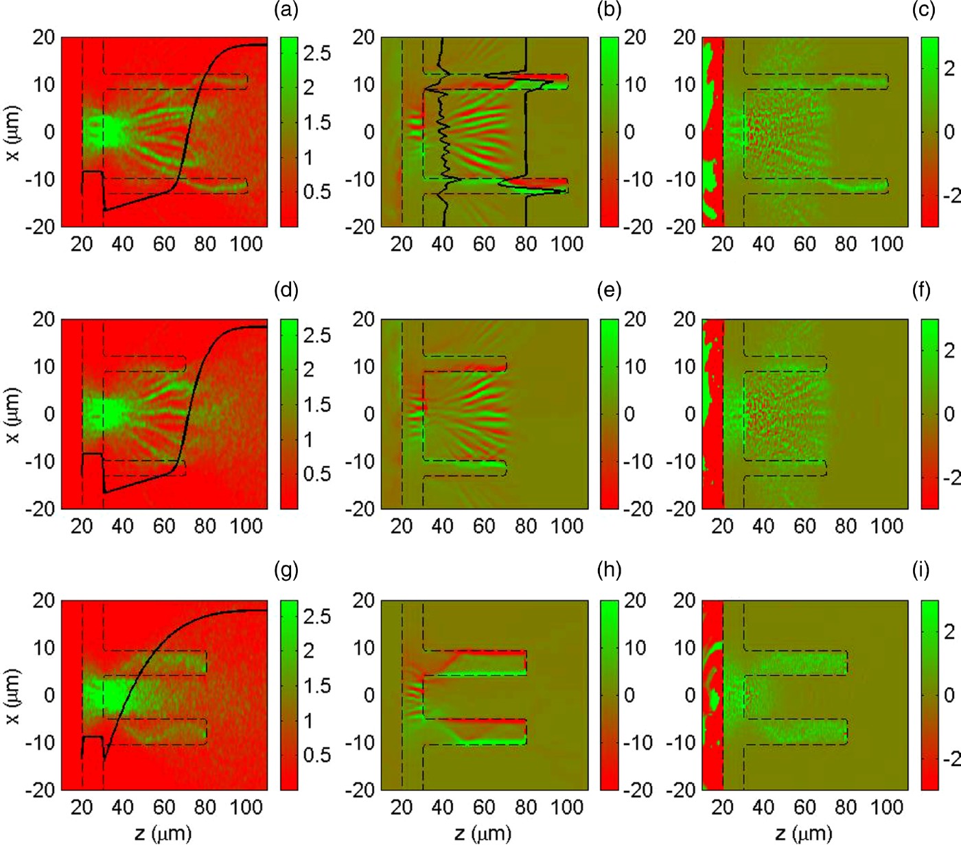
Fig. 2. (Color online) Snapshots of the hot-electron density, the magnetic and electric fields at t = 2 ps. (a, d, g) Hot-electron density (n b/n cr). The black solid line marks the electron density-profile in the beam propagation direction. (b, e, h) B y component of magnetic field (in MG). Two thick black solid lines in (b) gives B y-profiles located at z = 40 and 80 µm, respectively. (c, f, i) E z component of electric field (in TV/m). The thin dashed lines in all subplots show the gold plasma. The first to third rows correspond to cases I to III, respectively.
Figures 2–5 show energetic electron transport and heating for our 2D simulations at 2 ps. As the simulation progresses, the beam electrons are injected to the right from the injection plan (z = 20 µm), as shown in Figure 1b. As the fast electrons enter the gold plasma they set up a charge separation field. We see in Figures 2c, 2f, and 2i that the electric field can be larger than 3 × 10⁹ V/m. The field draws a return current of the background cold plasma electrons with current density (jr) larger than 1012 A/cm2. It is observed that strong positive electric field E z at around z = 30 µm (the interface between the gold and the DT plasma) behaves like the resistance to the beam current, in which the beam density is concernted, as seen in Figures 2a, 2d, and 2g. Since the non-zero net current can contribute to the generation of magnetic fields by ∇ × B = μ0jnet. The magnetic field of the beam pinches and collimates the beam electrons. Furthermore, the self-generated magnetic (SGM) fields grow in time according to Faraday's law ∂B/∂t = −∇ × E ≈ η∇ × jf + ∇η × jf, where η is the plasma resistivity and jf is the fast electron current, and the displacement current is neglected in the second expression.

Fig. 3. (Color online) The behavior of the beam electrons at t = 2 ps for three cases. (a), (d) and (g) correspond to the beam electron energy εb > 1.8 MeV. (b), (e) and (h) for 1.4 < εb < 1.6 MeV, (d), (f) and (i) for εb < 0.7 MeV. The thin red dashed lines show the gold plasma, and the thick green solid lines mark the electron density-profile of the gold-slab and DT plasmas in the beam propagation direction.

Fig. 4. (Color online) Snapshots of the plasma temperature (in eV) at t = 2 ps. (a, d, g) Fluid electron temperature. (b, e, h) Au ion temperature. (c, f, i) DT ion temperature. The green solid lines also mark the electron density-profile in the beam propagation direction. The thin dashed lines in all subplots show the gold plasma. The first to third rows correspond to cases I to III, respectively.

Fig. 5. (Color online) The plasma fluid electron and DT ion temperature profiles (in eV) at t = 2 ps for cases I, II and III. (a) and (c) correspond to z = 35 µm. (b) and (d) correspond to z = 65 µm.
When the electron beam enters the gold hollow and relative low-density DT plasmas, on one hand, a strong edge magnetic field is generated initially by η∇ × jf. This pushes the beam electrons toward the regions of higher current density and focusing the beam in the region of |x| < 10 µm, as shown in Figure 3. On the other hand, when the beam further propagates into the plasma, the beam electrons deposit their energy to the background plasma through the return current. Heating of the cold background plasma by joule heating of the return current can be described by the cold-electron energy equation (Glinsky, Reference Glinsky1995) ![]() , where κ, σ, and J e are the thermal conductivity, electrical conductivity, and the cold-electron current density, respectively. For relativistic beam electrons, the term ∇T e can be neglected since it is smaller than the other terms by a factor T e/T h. One can also neglect the hot-electron drag effect Q h since it is smaller than the joule heating term by a factor (T e/T h)3/2. Thus, joule heating J e2/σ dominates and result in higher temperature heating in the central region, as shown in Figures 4a, 4d and 4g.
, where κ, σ, and J e are the thermal conductivity, electrical conductivity, and the cold-electron current density, respectively. For relativistic beam electrons, the term ∇T e can be neglected since it is smaller than the other terms by a factor T e/T h. One can also neglect the hot-electron drag effect Q h since it is smaller than the joule heating term by a factor (T e/T h)3/2. Thus, joule heating J e2/σ dominates and result in higher temperature heating in the central region, as shown in Figures 4a, 4d and 4g.
Since the resistivity decreases as the plasma is heated by hot electrons, the resistivity gradient can appear at the beam-plasma edge. The source term ∇η × jf can therefore generate a magnetic field when there is a beam current perpendicular to a resistivity gradient. For a uniform plasma, this edge magnetic field hollows rather than focuses the beam. The resistive filamentation instabilities associated with the divergence of the electron beam in the region of 40 < z < 70 µm are clearly observed in the first and second rows of Figure 2. Importantly, the steepest gradients of both the resistivity and the plasma density at the interface between the gold hollow and the DT plasma also leads to the generation of large surface magnetic fields on their interface. The hot electrons in the relative low-density region can also be pinched by this resistive interface magnetic field.
To see how the hollow structure controls and guides the beam electrons, we shall compare the transport dynamics of the injected electron beam for three cases. Figure 3 shows the phase spaces of three different energy levels. For the injection electrons propagating in the relative low DT plasmas, one can see that the beam electrons are pinched by the interface magnetic fields appeared on the inner surface of the hollow (see Figs. 2b, 2e, and 2h). For cases I and III, the hollow has entered the dense DT core, in which the density of the DT plasma electrons is much higher than the gold-hollow plasma density. When the beam electrons enter the DT dense region, these electrons can be scattered into the gold hollow through collisions with the DT electrons and ions, as shown in Figures 2a, 2g and 3a, 3g. As the beam further propagates into the hollow plasma, the beam electrons also deposit their energy in background plasma through the return current and result in heating of the plasma in the gold hollow, as shown in Figures 4a, 4d, and 4g. Since the Spitzer resistivity η = 10−4ZlnΛT −3/2 is used, the resistivity decreases as the plasma is heated by hot electrons. Thus the source term ∇η × jf can change sign, as indicated by the solid black lines in Figure 2b, due to change of the net current at the interface as the DT plasma density increases in the propagation direction. This reversal of the interface magnetic fields appeared on both the inner and outer surfaces of the hollow, so the fields behave like a wall, which bends the beam electrons in the hollow into the axial direction. This bending process of the fast electrons by the magnetic potential around the hollow is clearly shown in Figures 2a and 2g, and Fig. 3.
In particuar, for high (or low) energy beam electrons with εb > 1.8 MeV (or εb < 0.7 MeV), Figures 3a and 3g (or 3c and 3i) clearly indicate that the beam electrons are guided by the hollow. For 1.4 < εb < 1.6 MeV, however, the control cannot be clearly observed from phase-space trajectories in Figures 3b, 3e, and 3h. Comparing Figures 3c, 3f, and 3i for the beam electron distributions, on the other hand, we can see clearly that there is stopping of the low-energy electrons at z = 30 µm. This anomalous stopping because of the strong interface electric field, as can be seen in Figures 2c, 2f, and 2i, results in a much higher electron population in the DT plasma close to the interface between the Au-tip and the DT fuel, as shown in Figures 2a, 2d, and 2g.
To further illustrate the importance of the hollow in guiding the beam electrons, we have considered a shorter hollow in case II, in which the hollow does not reached the dense core. As in case I, the surface magnetic field (higher than 20 MG) appeared in the inner layer of the hollow (Figs. 2b and 2e) can well bend the beam propagation along the central region when z < 40 µm. The filament beam then becomes divergent with its further propagation. In case II, the beam electrons have been scattered out the outer surface of the hollow before the magnetic wall can be formed on both the inner and outer surfaces of the hollow. Thus, the beam electrons cannot effectively be guided to propagate along the wall of the hollow in this case. By comparing Figure 2a with Figures 2d, or Figure 3c with Figure 3f for cases I and II, we observe that a longer hollow can indeed bend some beam electrons along the gold wall due to the magnetic guide of the hot-electron beam propagation in case I. The hollow-guided scheme is also dependent of the DT density profile of the hollow. In case III, the DT plasma has a short scale to reach the dense core. Comparing Figure 2g with Figures 2a and 2d, or Figure 3i with Figures 3c and 3f, it is obvious that the beam electrons in cases III is faster pushed into the hollow than in cases I and II.
The temperature of Figure 4 shows the coupling of the beam electron energy to the fluid plasma for the three cases. Figures 4a, 4d, and 4g show that the plasma electron temperature of the gold hollow becomes higher when the beam electrons are scattered into the wall of the hollow. Figures 4b, 4e, and 4h give the gold ion temperature for our three cases. The beam electrons deposit their energy in the region of relatively low-density DT plasmas through joule heating and this results in relatively nonuniform heating. Figure 5 give a comparsion of plasma electron and DT ion temperature profiles at z = 35 and 65 µm, respectively. Since the DT plasma density in cases I and II at z = 35 µm is lower than in case III, Figure 5a shows that the background electron temperature in cases I and II can grow (mainly due to joule heating) with a faster rate than that in case III. For cases I and II, the corresponding temperature profiles are of Maxwellian distribution, but for case III two new peaks in the wing are observed. These two small peaks correspond to the heating of the gold hollow. When the beam electrons further propagate into the hollow plasma, the background gold plasma electron is heated with higher temperature due to joule heating, as shown in Figure 5b for z = 65 µm. On the other hand, nonuniform heating of the DT plasma electrons in the region of |x| < 10 µm due to the beam filamentation (as shown in Figs. 2a and 2d) for cases I and II is also observed in Figure 5b. When the DT plasma density becomes higher, the electric field is almostly reduced and collisions between the hot electrons, and the cold plasma particles become the dominant heating mechanism. This can be clearly observed in Figures 4c, 4f, and 4i for three cases. In particular, Figure 5b indicates that this collision heating can lead to a more uniform temperatue profile (blue solid line) in the region of |x| < 5 µm for case III. The DT ion temperature profiles for our three cases at z = 35 and 65 µm are shown in Figures 5c and 5d, respectively. Because of the DT plasma density at z = 35 µm is higher than 1024 cm−3, the beam can mainly deposit its energy through scattering of pairs of relativistic electrons off the background plasmas. Therefore, the DT plasma ion can be heated to higher temperature in case III, as shown in Figure 5c. At z = 65 µm, the DT plasma density in case III has reached 1025 cm−3. Most of the low-energy beam electrons are stopped and high-energy electrons have scattered into the wall of the hollow before they reach this dense core. Thus, the DT plasma (electron and ion) temperature near the dense core in case III can be lower than in cases I and II, as shown in Figures 5b and 5d. Finally, it is noted from Figures 5c and 5d that large peak structures of the DT ion temperature close to both inner and outer surfaces of the gold hollow can be formed for all three cases. The increased surface heating in the hollow target seen in Figures 4 and 5 would possibly reduce energy coupling of the beam electrons into the dense fuel core.
4. CONCLUSION
In conclusion, transport and heating of energetic electrons driven by petawatt-picosecond pulse lasers in a new cone-hollow-guide target configuration have been investigated using two-dimensional hybrid simulations. It is shown that with the hollow guiding, the discontinuities in the density and resistivity between the gold hollow and the fuel plasma can lead to the generation of large surface self-generated magnetic fields on their interface. The energetic electrons in the region of the low-density DT plasma are quite well collimated by this resistive interface magnetic field. However, near the dense region, the beam electrons can be scattered into the gold hollow through collisions with the DT electrons and ions. Owing to change of the net current at the interface as the DT plasma density increases in the propagation direction, the interface magnetic fields in the inner and outer surfaces of the hollow can therefore change sign. This reversal of the interface magnetic fields appeared on both the inner and outer surfaces of the hollow, and the fields behave like a potential well that bends the beam electrons such that they propagate along the hollow. With proper geometries, the hollow structure can therefore pinch and guide the hot-electron beam propagation in dense DT plasmas and enhance the heating of the DT fuel. The hollow-guided scheme here can also be useful for other potential applications in plasma fibre and other high energy density physics where the guide and collimation of laser-driven electron beams are required.
ACKNOWLEDGMENTS
This work is supported by the National Natural Science Foundation of China, Grant Nos. 10974022 and 10835003, the National High-Tech ICF Committee and by the National Basic Research Program of China (973) (2007CB815101).


