


NOMENCLATURE
- e
error
- e dis
error generated by external power disturbances
- et
transient-state error in instruction trace process
- es
static-state error in instruction trace process
- n
propeller speed
- n REF
propeller speed command
- Δn
propeller speed difference
- nm
master propeller speed
- ns
slave propeller speed
- PR
power command
- α
phase angle
- Δα
phase difference
- ΔαE
control error of phase angle
- ΔαEC
control deviation of phase angle
- ΔαR
phase difference command
- αREF
phase angle command
- β
pitch angle
- βR
pitch command
Symbols
1.0 INTRODUCTION
Turboprop-driven aircraft has the advantage of low fuel consumption over turbofan-driven aircraft. However, it has the limitation of loud cabin noise and strong vibration because of propeller rotation. Propeller noise and vibration can lessen cabin comfortableness and cause material fatigue of airborne equipment. The interior noise levels of propeller-driven aircraft such as AP-3C Orion and C-130J-30 Hercules range from 85 to 100 dB(Reference Blunt and Rebbechi1). A noise reduction of 25 dB is needed in addition for advanced turboprop aircraft as mentioned above to make the noise the same level as turbofan aircraft(Reference Mathur2).
Propeller vibration and noise are mainly distributed in the low frequency domain (50–300 Hz), so traditional passive techniques such as the use of a double-wall structure or acoustic absorbing material have little effect on reducing the noise and vibration. Active noise control techniques such as the use of secondary acoustic sources or piezoelectric actuators are capable to reduce noise and vibration over a broadband of frequencies; however, full-scale implementations of these techniques have been hindered by electromechanical limitations of active materials(Reference Wickramasinghe, Zimcik and Chen3).
The propeller phase synchronisation control system of a turboprop engine is an active method to lower noise and vibration by utilising existing acoustic waves to cancel the unwanted noise. It is found that the maximum noise level in the cabin is eight times higher than the optimum level after synchrophasing(Reference Fuller4, Reference Jones and Fuller5). The noise reduction at individual sensors’ locations can sometimes exceed 20 dB(Reference Blunt6). The system is implemented without additional weight and power by the engine Full Authority Digital Electric Control (FADEC) system, for it employs the existing sensors and actuators to achieve phase control.
On the basis of considering the cooperation of propellers and engines, engine speed/synchrophasing control can optimise the propulsion efficiency and performance, and at the same time, reduce the cabin noise and vibration. Phase control is implemented by adjusting the pitch angle of the propeller. Therefore, it can be called the speed/synchrophasing control loop. Control algorithm must be considered carefully in order to meet the performance requirement of speed and phase control simultaneously.
Phase control accuracy has a great influence on the noise reduction effect of synchrophasing(Reference Magliozzi7). The inherent low bandwidth and hysteresis of the hydro-mechanical actuator are the limiting factors of tighter tolerance(Reference Schneider and Magliozzi8). The synchrophase angles oscillate by about ±5° in smooth air and may be larger in turbulent air. A reasonable phase control strategy and algorithm will improve the control precision and achieve a higher noise and vibration reduction.
In this paper, an integrated power/speed/synchrophasing control system is designed. To coordinate the control modules of power, speed and phase, speed/phase control transformation logic is studied. A fuzzy control algorithm is designed to meet the requirements of the control system. A slave-slave scheme is utilised instead of a master-slave scheme after verifying its superiority.
2.0 GENERAL DESIGN OF SPEED AND SYNCHROPHASING CONTROL SYSTEM
The integrated power/speed control system of a turboprop engine is shown in Fig. 1. The quantity of fuel and pitch angle are two inputs to the control system. The power is controlled by adjusting fuel flow WfR, and the speed is controlled by adjusting pitch angle βR.
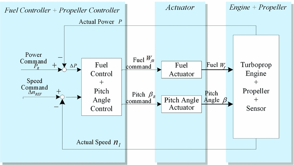
Figure 1. Integrated power/speed control of turboprop engine.
The integrated power/speed/synchrophasing control system of advanced turboprop engine is a comprehensive system based on the power and speed regulation system as illustrated in Fig. 2. Both speed and phase control are implemented by adjusting the pitch angle of the propeller, so no extra actuator or power is needed. Phase difference is obtained from the non-linear transformation of phase displacement(Reference Huang, Sheng and Wang9), which is the integration of speed. The phase control module is embedded in the speed/phase control transformation logic, which is incorporated with the power control system in an integrated power/speed/synchrophasing control system as illustrated in Fig. 2. The output of the synchrophasing control module, Δn ref, is super-imposed on propeller speed command, which is essentially a bias signal to the propeller speed reference.
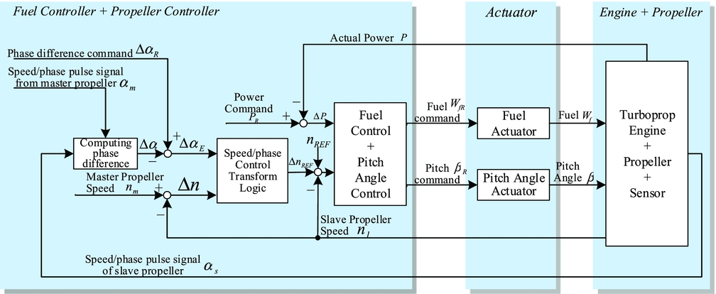
Figure 2. Integrated power/speed/synchrophasing control of turboprop engine.
The speed and phase difference control loop may be easier to implement when regarding the phase displacement as the reference value rather than super-imposing a bias signal to speed command. When the phase displacement is added to the system as a reference value, the position closed-loop control takes the place of the speed closed-loop control. In this case, the output is integration of speed, which adds an integral item to the open-loop transfer function of the system and increases the risks of vibration and overshoot. The close-loop control of phase makes no sense when a large error of speed exists. Therefore, the strategy of super-imposing a signal to speed command is selected. Speed/phase control transformation logic, which is elaborated in the next section, is introduced to generate the bias signal and reduce overshoot.
Fuel flow command is provided by power control loop according to the reference value PR from the power level. Phase and speed control is implemented simultaneously via the pitch angle modulation.
3.0 SPEED AND SYNCHROPHASING CONTROL INTEGRATION METHOD
Speed and synchrophasing control integration method is implemented by the speed/phase control transformation logic. As shown in Fig. 3, speed/phase control transformation logic mainly consists of the input signal processing, multi-blade phase plane logic and speed/phase control. It provides correction Δn REF to the reference speed.

Figure 3. Speed/phase control transformation logic.
The control mode is chosen according to the magnitude of the propeller speed difference Δn and the control error of phase angle ΔαE. A propeller synchrophaser has a speed control mode initially and brings the speed of the slave propeller to within a selected constant number of r/min of the target speed, and then it switches to the phase mode when the magnitudes of Δn and ΔαE are less than a predefined threshold. The speed/phase switching method can take both the rapidity of speed response and phase control precision into account. There exists switching oscillation during the mode transform process for the sudden changes of the controlling quantity.
3.1. Speed/phase control transformation logic
In the input signal process module,
 $$\begin{equation}
\Delta n = {n_m} - {n_s}\\
\end{equation}$$
$$\begin{equation}
\Delta n = {n_m} - {n_s}\\
\end{equation}$$
 $$\begin{equation}
\Delta {\alpha _E} = \Delta {\alpha _R} - \Delta \alpha ,
\end{equation}$$
$$\begin{equation}
\Delta {\alpha _E} = \Delta {\alpha _R} - \Delta \alpha ,
\end{equation}$$
A bias signal Δn REF from the speed/phase control module will be super-imposed onto the speed reference of the blade pitch control loop when the phase or speed difference between master and slave propellers is beyond the control tolerance.
The phase error for speed/phase control ΔαEC is determined by ΔαE and Δn according to the multi-blade phase plane(Reference Niessen10) logic in order to solve the cooperation problem between synchrophasing control and speed control, as illustrated in Fig. 4, in which the shaded region is the normal phase varying zone. For a particular blade, the region within the trajectory of F(αE) and − F(− αE) defines the region for phase holding, where ΔαEC = Δα. For a propeller with three blades, possible ranges for ΔαEC are ± 180° and ± 60°. Present propeller synchronisers utilise one electrical pulse per propeller revolution so that a sensed phase provides a phase error measurement up to ± 180°. In view of the actual working condition and the universality, the description herein is based on the assumption that the range is ± 180°. For a propeller with three blades, the range can be ± 60°. When the trajectory lies outside the normal control zone, let ΔαEC remain − 180° or + 180° until it enters the normal zone. For a multi-blade propeller, the control phase plane diagram of a particular blade connects the phase plane of the subsequent blade. Figure 4 shows a synchrophasing control state with the initial position on the normal region of blade 1, its trajectory will run out of this region under disturbance and then ΔαEC will be set to − 180°. When it enters the region of blade 2, there will be a value jump of phase error from − 180° to + 180°, and judgment criterion of the phase error will be applied. Under synchrophasing control, the trajectory can run along the reference trajectory and eventually set at the point where ΔαEC = 0 and Δn = 0. Multi-blade phase plane and the corresponding logic have the following merits:
(1) When the phase error and speed error are large, the control authority of the phase error is limited by setting ΔαEC to + 180°, and the speed error is the dominant control input. Normal phase control can work only when the phase error is small enough. Speed control and phase control can cooperate well within the same control loop without switching between two loops.
(2) This logic can switch the control region from blade 1 to blade 2 automatically, when the phase error that lies on the phase 1 region slips to that of phase 2. That is to say, phase difference between master and slave propellers is defined according to the two nearest blades, not the fixed ones; therefore, a significant quicker control speed can be obtained.

Figure 4. Control trajectory in multi-phase plane diagram.
3.2. Simulation result of speed/phase control transformation strategy
Figure 5 is the step response curve when the speed/phase transformation strategy is adopted. The simulation is carried out in 100% RPM. The step time is about 3 seconds. Simulation is also conducted in the same conditions for comparison when regarding the phase displacement as the reference value, when the step time is about 20 seconds. It can be seen that the system designed in this article can respond more quickly to a large step phase difference command of 20°. Phase transient has little impact on propeller speed and pitch angle.
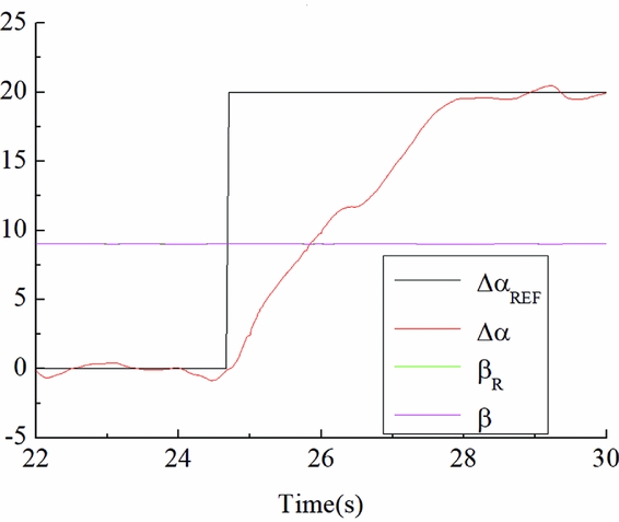
Figure 5. Simulation result of speed/phase transform strategy.
3.3. Discussion of the application of the speed and synchrophasing control integration method
(1) The effects of super-imposing signals directly onto the commands to actuators
In the method mentioned above, the bias signal generated by speed/phase control transformation logic is super-imposed on the speed command. Super-imposing a bias signal onto the command to the pitch angle actuator can adjust phase angle, too.
The bias signal super-imposed on the actuator command can be seen as a Pulse Width Modulation (PWM) wave with three adjustable parameters: frequency, amplitude and duty. Larger amplitude leads to a shorter adjusting time but a greater disturbance on the speed/power control system. Stringent duty cycle and low frequency can hardly take effect. However, the effects of signals with higher duty cycles may be offset by the closed-loop control as errors. The actuators cannot timely adjust when the frequency is too high. For an electro-hydraulic servovalve with high inertia, it can only respond to signals with limited bandwidth. For these reasons, super-imposing signals directly on the commands to actuators may lead to slow response or great disturbance on the propeller speed.
(2) The effect of actuator dead zone and clearance
There exist a dead zone and a clearance in the actuators of a turboprop engine; thus the actuators do not respond to a small phase difference. Then the control signal will accumulate because of integral control effect, leading to overshoot. The actuators cannot response timely to reverse control command when the overshoot appears until the reverse control command accumulates to the boundary of the dead zone. The reciprocating phenomenon results in an oscillation around the target position which develops into limiting circle oscillation.
The fuel-power control loop in Fig. 2 has non-linear features caused by the clearance and dead zone of the actuators. In order to minimise the impact of clearance, a noise signal of 400 Hz with low magnitude is super-imposed onto the input to the electro-hydraulic servovalve. The negative effects of clearance can be ignored with the help of the noise signal. Therefore, the power control system can respond to small control command. This method cannot be applied to the speed control system, for high frequency noise exacerbates the wear and lowers the life cycle of actuators. There is large lag in the transient process of speed regulation by adjusting fuel flow. Therefore, the approach of super-imposing signals directly onto power command is not feasible.
4.0 SPEED/PHASE CONTROL ALGORITHM AND SLAVE-SLAVE CONTROL SCHEME
4.1. Fuzzy logic algorithm
Fuzzy logic algorithm is introduced to generate speed command difference in the speed/phase control module, as shown in Fig. 6.
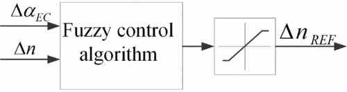
Figure 6. Speed/phase control module.
The unified domain of speed error and phase error is {–1,–2/3, –1/3,0,1/3,2/3,1} after normalisation; the corresponding language value is {NB,NM,NS,ZO,PS,PM,PB}, with the triangular membership function, as shown in Fig. 7.
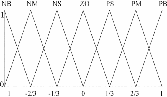
Figure 7. Membership function of Δn and ΔαEC.
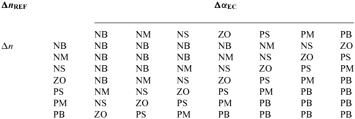
The language value of the speed reference bias signal can be obtained through fuzzy rules as shown in table 1, with the collection of {NB, NM, NS, ZO, PS, PM, PB}; the corresponding normalised speed array is {0,1/6,1/3,1/2,2/3,5/6,1}. Triangular membership function is also applied to the speed reference bias signal.
Table 1 Fuzzy control rule table
4.2. Slave-slave control scheme
In the master-slave control scheme, one of the propellers is designated as the master propeller and the remaining propellers are slaves to this master. The major disadvantage of this scheme is, when there are perturbations in the speed of the master propeller possibly caused by turbulence or power variation from operation of pilot, all the slave propellers have to be unnecessarily adjusted even though they may not been similarly perturbed.
Alternative solution, slave-slave scheme, is to generate a virtual master via software and make all the propellers slaves. This makes it feasible to transmit signals by bus and improves the engineering implementability of synchrophasing.
4.3. Digital simulation
Synchrophasing control has been verified by simulations. Figure 8 shows the comparison result of the control effects between master-slave scheme and slave-slave scheme, with a speed step input at 0 s and a phase difference step at 8 s. The perturbations of the propellers are simulated by applying Gaussian noise on the acceleration of the speed. The mean square deviation between 8 s to 10 s is 0.32° for slave-slave mode and 0.45° for master-slave mode. Compared with master-slave scheme, phase fluctuation in case of speed step perturbation has been suppressed effectively by applying slave-slave scheme.
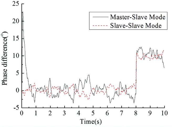
Figure 8. Simulation results of master-slave control scheme and slave-slave scheme.
Figure 9 illustrates the effect of the designed fuzzy logic algorithm by comparing it with the result of phase-locked loop control. The slave-slave control scheme is selected. The control target herein itself is a coasting body. Introducing inertia items will cause higher oscillating amplitude and slower response speed. Thus, the phase-locked loop used herein adopts no inertia items. The mean square deviation between 8 s to 10 s is 0.29° for fuzzy logic and 0.47° for phase-locked loop. Results show that fuzzy control can suppress the influence of the exterior interference and follow the variation of the phase difference command well.
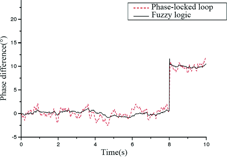
Figure 9. Simulation results of PLL control and fuzzy logic algorithm.
4.4. Discussion of effect of slave-slave scheme in suppressing phase fluctuation
Compared to master-slave control scheme, slave-slave control scheme can reduce the phase fluctuation from exterior perturbation. Therefore, it can be applied to a distributed engine control system in which all the signals are transmitted by bus.
The sum of absolute phase error in Fig. 8 from 2 s to 7 s (during the steady-state process) is:
 $$\begin{equation}
\frac{{\sum {\left[ {{e_{{\rm{slave}} - {\rm{slave}}}}} \right]} }}{{\sum {\left| {{e_{{\rm{master}} - {\rm{slave}}}}} \right|} }} = 54.2\%
\end{equation}$$
$$\begin{equation}
\frac{{\sum {\left[ {{e_{{\rm{slave}} - {\rm{slave}}}}} \right]} }}{{\sum {\left| {{e_{{\rm{master}} - {\rm{slave}}}}} \right|} }} = 54.2\%
\end{equation}$$
From Equation (Reference Wickramasinghe, Zimcik and Chen3), it can be concluded that steady-state error under exterior inference has been reduced. The reason for the improvement of noise reduction can be inferred that the phase fluctuation from master due to speed perturbation when adopting master-slave scheme can be regarded as command input of the slave control system and result in phase fluctuation of slaves. However, this phenomenon does not exist in a slave-slave scheme.
The phase difference fluctuation is mainly composed of:
 $$\begin{equation}
\Delta \alpha = \Delta {\alpha _{{\rm{REF}}}} + {e_{{\rm{dis}}}} + {e_t} + {e_s},
\end{equation}$$
$$\begin{equation}
\Delta \alpha = \Delta {\alpha _{{\rm{REF}}}} + {e_{{\rm{dis}}}} + {e_t} + {e_s},
\end{equation}$$
where ΔαREF is the reference of phase difference, e dis is the error due to exterior power disturbance, et and es are the transient-state error and steady-state error, respectively, in the process of tracking reference value. The steady-state error es can be eliminated eventually by close-loop control. The transient-state error et exists when the reference value changes.
The phase error in the master-slave scheme:
 $$\begin{equation}
\Delta \alpha = \Delta {\alpha _{{\rm{REF}}}} + {e_{{\rm{dis}}\;2}} - {e_{{\rm{dis}}\;1}} + {e_{t2 - 1}},
\end{equation}$$
$$\begin{equation}
\Delta \alpha = \Delta {\alpha _{{\rm{REF}}}} + {e_{{\rm{dis}}\;2}} - {e_{{\rm{dis}}\;1}} + {e_{t2 - 1}},
\end{equation}$$
where propeller 1, the master, is followed by propeller 2, the slave. e dis 1 and e dis 2 are the error of propeller 1 and 2 due to exterior power disturbance. e t2 − 1 is the transient-state error caused by fluctuation of reference value which is actually the speed of master propeller.
The phase error in the slave-slave scheme:
 $$\begin{equation}
\Delta \alpha = \Delta {\alpha _{{\rm{REF}}}} + {e_{{\rm{dis}}\;2}} - {e_{{\rm{dis}}\;1}},
\end{equation}$$
$$\begin{equation}
\Delta \alpha = \Delta {\alpha _{{\rm{REF}}}} + {e_{{\rm{dis}}\;2}} - {e_{{\rm{dis}}\;1}},
\end{equation}$$
where e t2−1 in Equation (Reference Jones and Fuller5) is zero. It is because the commands tracked by propellers 1 and 2 are from a virtual master. The commands are the same and constant and not affected by the fluctuation of the master propeller.
e t2−1 is not included in Equation (Reference Blunt6) when compared with Equation (Reference Jones and Fuller5); therefore, control precision can be improved in the slave-slave scheme. The system can offer better capabilities of anti-interference, especially in this case of large fluctuation.
5.0 SIMULATION OF THE INTEGRATED SPEED/SYNCHROPHASING CONTROL SYSTEM OF TURBOPROP ENGINE
A synchrophasing system including two propellers is simulated. The component-level model of a turboprop engine(Reference Huang, Huang and Zhang11) and the non-linear propeller model(Reference Deng, Huang and Chao12) are adopted. The input condition is: altitude H = 0 km, Mach number M = 0, the propeller speed Np is controlled to 100% and engine power is to the designed value. Zero mean Gaussian white noise power disturbance with the maximum value of ± 60 kw is applied to the two propellers.
The integrated power/speed/synchrophasing control is adopted in the engine control system, as shown in Fig. 2, with the control step of 20 ms for outer loops and 5 ms for the inner actuator loops of fuel and pitch angle. As shown in Fig. 3, the output of speed/phase control logic adopts a fuzzy algorithm to generate the propeller speed reference bias from speed error and phase error, and the bias value is limited within 0.1% range of the speed reference. Slave-slave scheme is adopted.
Simulation results of synchrophasing control for two schemes are shown in Figs 10 and 11. It can be seen that the designed power/speed/synchrophasing control system can respond quickly to large step phase difference command of 20°. The step time is about 3 seconds. The mean square deviation between 120 s to 500 s is 0.48° and no obvious oscillation is found. The control error is in an acceptable range.
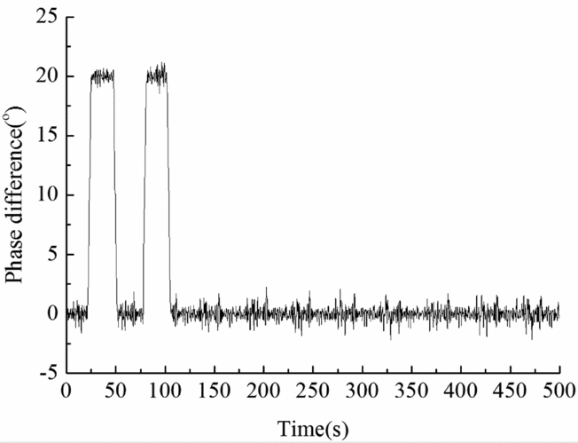
Figure 10. Step response of slave-slave control scheme.
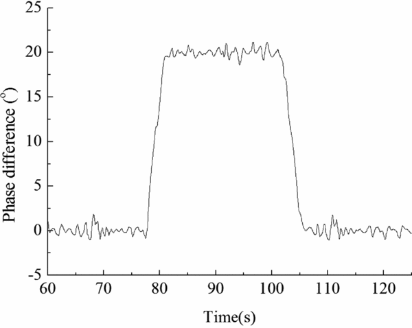
Figure 11. Detail view of Fig. 10.
6.0 CONCLUSION
Integrated power/speed/synchrophasing control of a turboprop engine is studied. This control system is based on a traditional engine fuel and speed regulation system by super-imposing a phase control command onto speed command; thus, no additional weight and power are needed.
Speed/phase transformation logic based on a multi-blade phase plane can improve both the respond rapidity of speed and synchrophasing control.
A fuzzy logic algorithm is designed to meet the requirements of the control system. Phase fluctuation caused by speed perturbations in case of turbulence or power variation can be suppressed when adopting a slave-slave control scheme. Therefore, compared with a master-slave scheme, a slave-slave scheme will be more suitable for a distributed control system transmitting signal with a bus.
The control effects of speed/phase control transformation logic and the whole control system are demonstrated by simulation. The results show that the control system meets the control requirements of a turboprop engine, and higher precision and rapidity can be acquired by using the new control algorithm.
ACKNOWLEDGEMENT
The authors wish to thank the National Natural Science Foundation of China (51576097) for the financial support. This work was supported by Funding of Jiangsu Innovation Program for Graduate Education (KYLX16_0357) and the Fundamental Research Funds for the Central Universities.


