Introduction
With the emerging technology of wireless communication, microstrip antennas have gained large interest due to their compact size, light weight, ease of fabrication, and integration on small-scale electronic devices. Using planar microstrip technology also provides an efficient way to achieve multiband operation on a single device which is very useful to access several wireless services such as Wireless Local Area Network (WLAN), Worldwide Interoperability for Microwave Access (WiMAX), Long Term Evolution (LTE), etc., which are widely used in wireless communication devices. Various microstrip antennas are available in the literature that offer dual-band and triple-band characteristics such as asymmetric M-shaped antenna [Reference Peng, Ruan and Wu1], H-shaped slot antenna [Reference Chang and Kiang2]. Defected ground structure (DGS) antennas are also presented for dual-band application [Reference Gautam and Kanaujia3]. These conventional microstrip antennas offer several challenges in terms of miniaturization, multiple frequency operation, bandwidth enhancement, gain, and efficiency improvement, etc. This led to the emergence of artificially engineered structures called metamaterials which exhibit exclusive electromagnetic properties that are not found in nature. Such metamaterials can be utilized in planar technology to overcome various challenges of microstrip antennas.
Various authors have demonstrated the use of metamaterials in planar antennas for the purpose of antenna miniaturization, multi-band operation, gain, and bandwidth improvement. A triple band monopole antenna is presented in [Reference Zhu, Antoniades and Eleftheriades4] that uses single-cell metamaterial loading along with DGS ground plane to achieve tri-band operation. Ha et al. [Reference Ha, Kwon, Lee and Choi5] presented a metamaterial unit cell comprising an interdigital capacitor and a complementary split-ring resonator (CSRR) slot. This antenna offers wideband operation and high efficiency up to 96%. Further, a metamaterial inspired patch antenna is presented for miniaturization [Reference Ouedraogo, Rothwell, Diaz, Fuchi and Temme6]. To reduce antenna size and improve bandwidth, a CSRR is placed horizontally between the bottom ground plane and the top patch. However, size reduction after a certain limit led to a reduction in radiation efficiency and fractional bandwidth which is undesirable. A compact antenna with enhanced bandwidth is presented in [Reference Majedi and Attari7]. The size of the antenna is reduced by using an epsilon negative transmission line (ENG TL). Zhou et al., also presented a metamaterial inspired antenna for Global System for Mobile (GSM)/Universal Mobile Telecommunications System (UMTS)/LTE/WLAN wireless communication systems [Reference Wang and Feng8]. The antenna shows a bandwidth enhancement of 40.2% by using a resonant ring as compared with the conventional antenna. Recently, the use of the interdigital capacitor is presented in [Reference Chi and Shih9] to enhance bandwidth. By properly designing the interdigital capacitor, Q-factor of the resonant antenna can be reduced, thus, improving the bandwidth.
Metamaterials are also used for mutual coupling reduction in multiple input multiple output (MIMO) antennas such a closely spaced metamaterial MIMO antenna with high isolation is presented in [Reference Abdalla and Ibrahim10]. A simple defected ground structure is used between two antennas to limit the surface waves and provide mutual coupling better than −45 dB. Table 1 gives a brief performance comparison of the proposed antenna with other previously reported metamaterial-based antennas along with their respective unit cell configuration. The overall size of the antenna is given in terms of λ 0, which is the wavelength corresponding to the lowest resonant frequency.
Table 1. Comparison of the proposed antenna with other reported antennas.

In this paper, a dual-band compact sized antenna utilizing triangular double split-ring resonator is presented. Most of the structures we have studied so far consist of either circular or square geometries while using triangular geometry is quite rare. The triangular structure offers relatively compact size and easy side-by-side coupling. The proposed antenna covers the entire spectrum of WLAN bands. The operating bands for this technology are assigned by IEEE 802.11 are 2.4 GHz (2.4–2.484 GHz), 5.2/5.8 GHz (5.15–5.35 GHz/5.725–5.825 GHz). The proposed antenna operates on the following bands: 2.4–2.48 and 4.7–6.04 GHz, thus, offering dual-band characteristics to cover WLAN bands. Simulations are performed using ANSYS High frequency structure simulator.
Material parameter extraction
Figure 1 shows the schematic of the proposed modified triangular split ring resonator (TSSR) unit cell. The proposed metamaterial unit cell is designed on an FR-4 dielectric substrate having dielectric constant (ε r) 4.4 and loss tangent (tanδ) = 0.02 with dimensions 16 × 12 × 1.6 mm3. The structure comprises a double TSSR having splits on the opposite arms and an open-ended stub connected at a distance of 0.8 mm below the outer ring. The width of each split ring is 0.9 mm with a split gap of 1 mm. The average length of the outer ring is 35.87 mm, and that of the inner ring is 19.03 mm. In order to extract the material parameters, i.e. effective permittivity (ε), permeability (μ), refractive index (n), and wave impedance (z), the structure is placed inside a waveguide medium (Fig. 1). The structure is placed inside a waveguide with two waveguide ports along the positive and negative y-axis. The ports are excited by the electromagnetic wave along the y-direction. The perfect electric and perfect magnetic boundaries are assigned along the x-axis and z-axis, respectively.
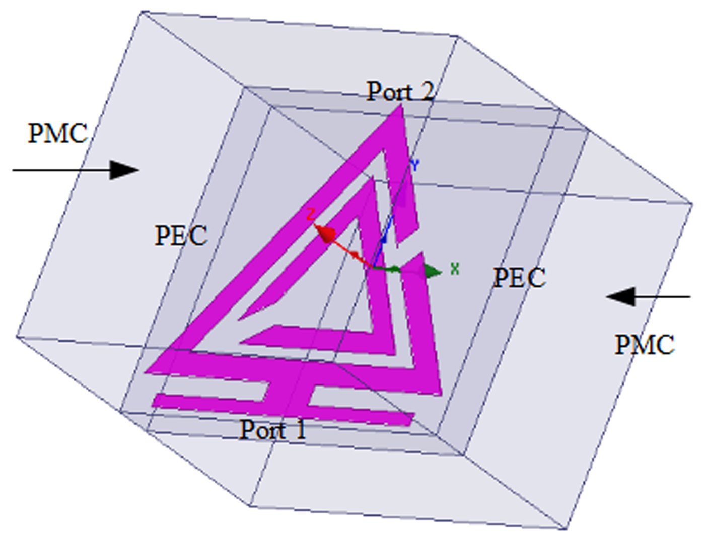
Fig. 1. Simulation setup of proposed metamaterial unit cell.
Now, effective medium parameters are extracted from the simulated complex scattering parameters using the modified Nicolson–Ross–Weir relations presented in [Reference Smith, Vier, Koschny and Soukoulis12]. Taking two arbitrary variables given by equations (1) and (2):
 $$V_1 = \; S_{21} + S_{11},$$
 $$V_2 = \; S_{21}-S_{11}.$$
Complex normalized wave impedance (z) can be obtained by equation (3):
 $$z = \sqrt {\displaystyle{{{(1 + S_{11})}^2-S_{21}^2} \over {{(1-S_{11})}^2-S_{21}^2}}}. $$
Now, permeability (μ), permittivity (ε), and refractive index (n) are obtained simply by equations (4)–(7):
 $$\mu _r = \displaystyle{2 \over {\,jkd}}.\displaystyle{{1-V_2} \over {1 + V_2}},$$
 $$\varepsilon _r = \displaystyle{2 \over {\,jkd}}.\displaystyle{{1-V_1} \over {1 + V_1}},$$
 $$\varepsilon = n/z,$$
 $$\mu = n.z.,$$
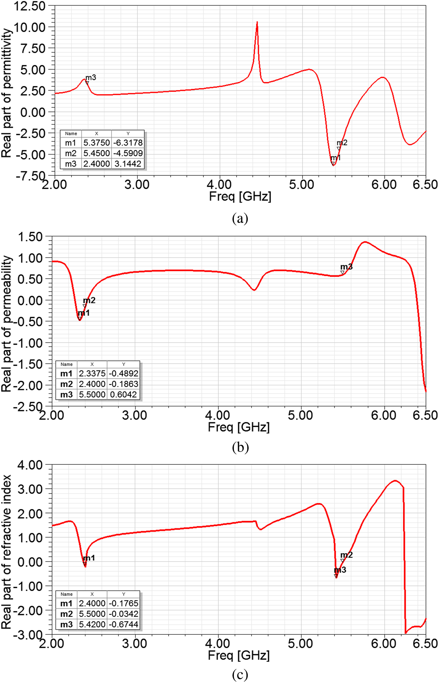
Figures 2(a)–2(c) shows the real part of the extracted parameters as a function of frequency along with their respective values at the desired frequencies. From Figs 2(a) and 2(b), it can be observed that negative effective permittivity and negative effective permeability are obtained at 5.45 and 2.4 GHz, respectively. Thus, the structure shows single negative behavior at the two desired resonant frequencies. Table 2 gives the values of permittivity, permeability, and refractive index at the desired resonant frequencies.

Fig. 2. Real part of permittivity (a), real part of permeability (b), and real part of refractive index (c).
Table 2. Real values of ε, μ, and n.

Antenna design and simulation approach
Figure 3 illustrates the geometry and dimensions of the proposed dual-band antenna using metamaterial inspired triangular SRR. It is fabricated using an FR-4 dielectric substrate of thickness 1.6 mm. The proposed antenna has a compact size of only 20 mm × 24 mm or 0.16λ 0 × 0.19λ 0 where λ 0 is the lower resonant frequency of antenna i.e. 2.45 GHz. We employ 50-Ω coplanar waveguide (CPW) and square ground plane to feed the antenna. Thus, the proposed metamaterial inspired antenna uses double TSSR, an open-circuited stub and rectangular ground plane to excite the dual-band operation at the desired frequencies.

Fig. 3. Schematic of the proposed dual band antenna.
Table 3 gives the design parameters of the proposed antenna structure shown in Fig. 3.
Table 3. Design parameters of the proposed antenna.

The two resonant frequencies at 2.45 and 5.45 GHz are achieved with the help of the triangular SRR. Since electrically small antennas have a disadvantage of poor impedance matching, an open-circuited stub is used in order to overcome this problem. It also helps in bandwidth enhancement of the antenna at higher frequency band. The open-circuited stub is etched just below the triangular SRR, as shown in Fig. 3.
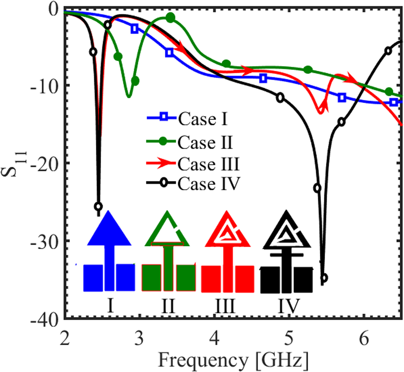
Now, Fig. 4 shows a stepwise procedure to obtain the required frequency band. It demonstrates the effect of including triangular SRR and open-circuited stub on the reflection coefficient of the antenna. The figure shows that in the case I when we have a simple triangular patch geometry, the band obtained with reflection coefficient >−10 dB is beyond 5 GHz.

Fig. 4. Stepwise procedure to obtain desired frequency bands.
As soon as the conventional triangular shape is replaced with the metamaterial inspired single triangular split ring geometry (case II), the band shifts towards lower side near 2.6 GHz. Further adding another split ring inside the previous one (case III) displays dual-band characteristics. Two resonant frequencies are obtained, one at 2.45 GHz and other at 5.45 GHz, achieving structure miniaturization by nearly 2.5 times. But still, the antenna does not show a good amount of impedance matching. For improving the impedance matching, an open-circuited stub is etched just below the triangular SRR as shown in Fig. 4 (case IV). It improves the impedance bandwidth at a higher frequency band. Thus, we observe dual-band characteristics with quite good impedance matching covering entire WLAN band.
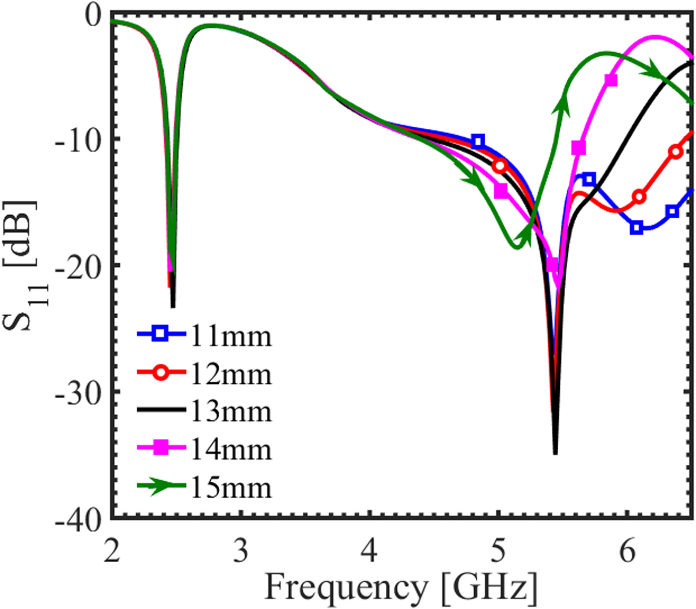
The effect of adding open-circuited stub can be further investigated with the help of parametric study of the length of the stub i.e. W p3, as shown in Fig. 5. It shows that the open-circuited stub causes a great impact on the impedance matching of the higher frequency band at 5.45 GHz. As the length W p3 increases from 11 to 15 mm, the lower and upper cut-off frequencies of the band shift towards higher side. It can also be seen that increasing the length W p3 from 11 to 13 mm leads to improved impedance matching which again deteriorates by increasing the length further. Thus W p3 = 13 mm is selected to be the optimum stub length providing maximum impedance matching along with covering the entire desired frequency band.

Fig. 5. Effect of variation of open-circuited stub length W p3.
Results and discussion
Impedance performance
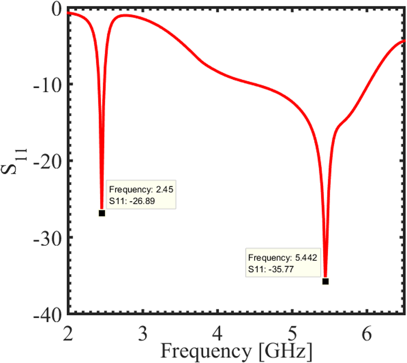
For a practical antenna system, it is required to have a reflection coefficient better than −10 dB for the desired band operations. This implies an acceptable amount of radiated power from an antenna. Figure 6 shows the simulated reflection coefficient of the proposed metamaterial antenna. It shows that the antenna operates in the desired frequency bands ranging from 2.40 to 2.48 GHz with −27 dB reflection coefficient at resonant frequency 2.45 GHz and 4.7–6.04 GHz with −36 dB reflection coefficient at resonant frequency 5.45 GHz, which covers the entire WLAN band spectrum (2.4/5.2/5.8 GHz).

Fig. 6. Simulated S-Parameters against frequency for the dual band antenna.
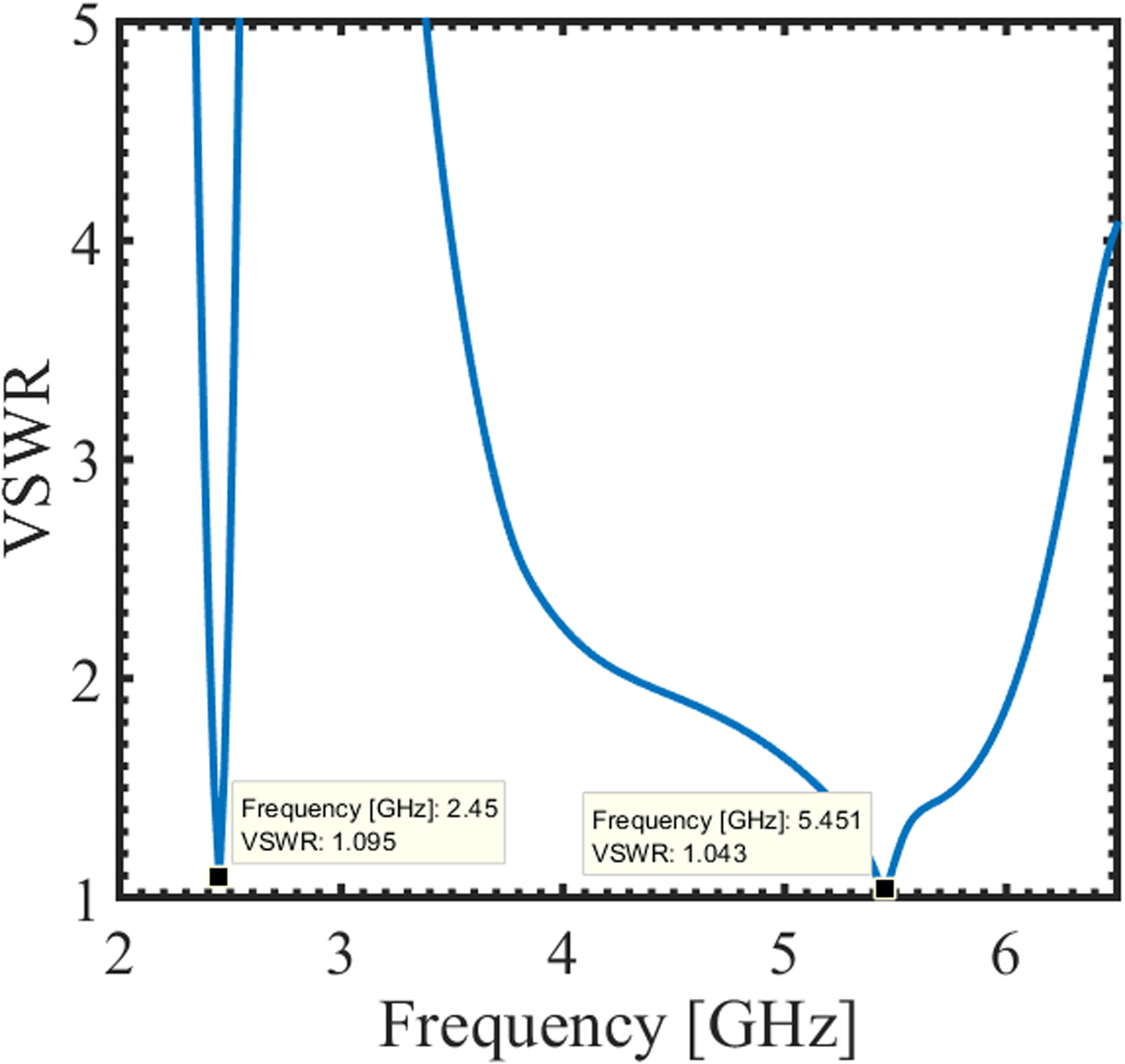
The variation of Voltage Standing Wave Ratio (VSWR) with respect to frequency shows that for both the operating bands its value is <2, as illustrated in Fig. 7. At the lower resonant frequency of 2.45 GHz, VSWR is 1.095 and at the upper resonant frequency of 5.45 GHz, it is 1.043 which is very close to 1 that shows excellent impedance matching.

Fig. 7. VSWR of proposed antenna.
Current distribution analysis
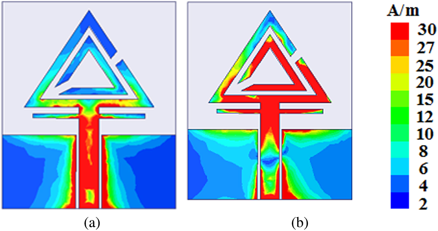
In order to provide further physical insight into the results, the simulated surface current distributions are plotted at the sample frequencies of 2.45 and 5.45 GHz, respectively, as shown in Figs 8(a) and 8(b). From Fig. 8(a), one can find that strong surface currents concentrate on the outer ring of the triangular SRR. Therefore, we can conclude that the 2.45 GHz WLAN band resonance occurs mainly due to the outer ring of the triangular SRR while the open-circuited stub is responsible for impedance matching at this band. For the 5.45 GHz operation (see Fig. 8(b)), it can be seen that the current density is maximum on both the rings of triangular SRR; hence, that is responsible for resonance at 5.45 GHz, again the open-circuited stub is responsible for impedance matching at this band also. Thus, from the current distribution, it can be concluded that the proposed antenna can provide dual band operation covering the 2.4/5.2/5.8 GHz WLAN.

Fig. 8. Simulated surface current distributions at (a) 2.45 GHz and (b) 5.45 GHz.
Radiation performance
The 2D simulated radiation characteristics in terms of directivity of the proposed antenna at the two resonant frequencies, i.e. 2.45 and 5.45 GHz, are shown in Fig. 9. First two columns i.e. Figs 9(a), 9(b), 9(e) and 9(f) corresponds to azimuth angle φ = 0°, 90° for all values of θ last two columns i.e. Figs 9(c), 9(d), 9(g) and 9(h) corresponds to the elevation angle θ = 0°, 90° for all values of φ. The radiation is symmetric and bidirectional in the main plane, however, seems to be radiating in all directions in the orthogonal plane. Thus, the proposed antenna gives nearly omnidirectional radiation pattern or a monopole antenna type of response. Also, the radiation seems to nearly stable across the frequency band.
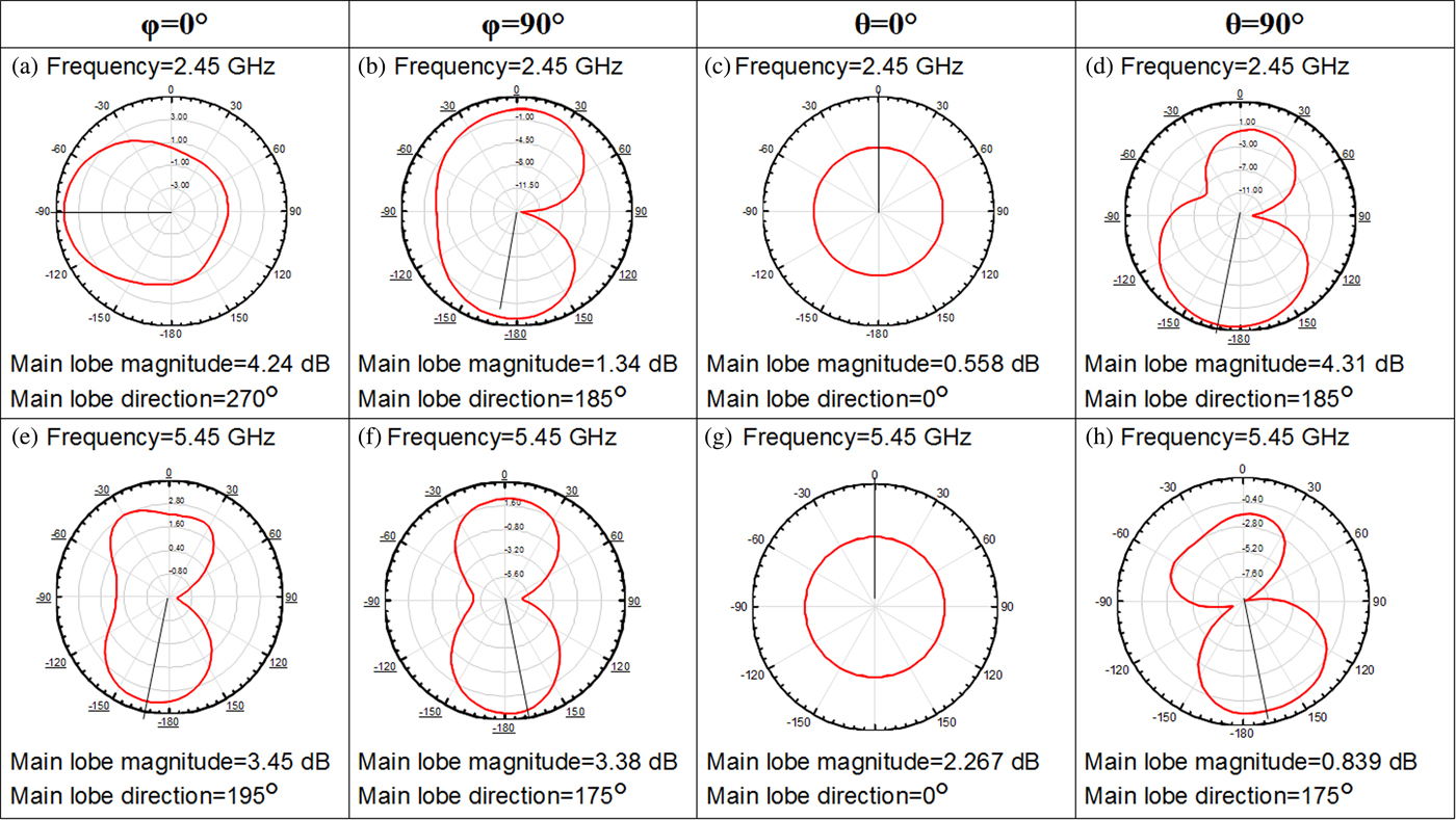
Fig. 9. The simulated 2D radiation pattern at frequencies 2.45 GHz (a–d) and 5.45 GHz (e–h).
Figure 10 shows the simulated peak gain and total efficiency for the operating bands. Results show that 62.53% efficiency at 2.45 GHz and 93.25% efficiency at 5.45 GHz is achieved. The gain observed is 3.129 to 1.435 dB for 2.4–2.48 GHz band and 2.319 to 2.907 dB for 4.7–6.04 GHz band. Thus, a good amount of gain and high radiation efficiency have been achieved at the two frequency bands of the metamaterial inspired antenna.
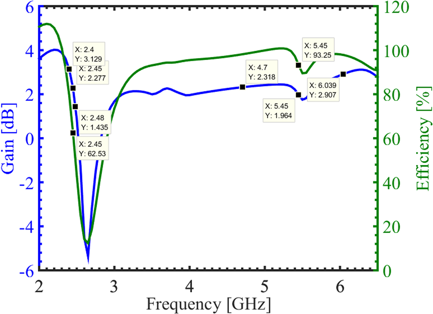
Fig. 10. Efficiency and gain plots of the metamaterial antenna.
Table 4 gives a performance comparison of the proposed metamaterial inspired antenna with previously proposed dual-band antennas covering WLAN band spectrum in terms of various antenna properties. From Table 4 we can conclude that the proposed antenna offers comparatively a large amount of reflection coefficient and small size along with wide impedance bandwidth at the higher frequency band. However, the gain can be further improved at the higher order band.
Table 4. Comparative analysis of proposed antenna and previously proposed antennas operating on WLAN band.

Experimental results and discussion
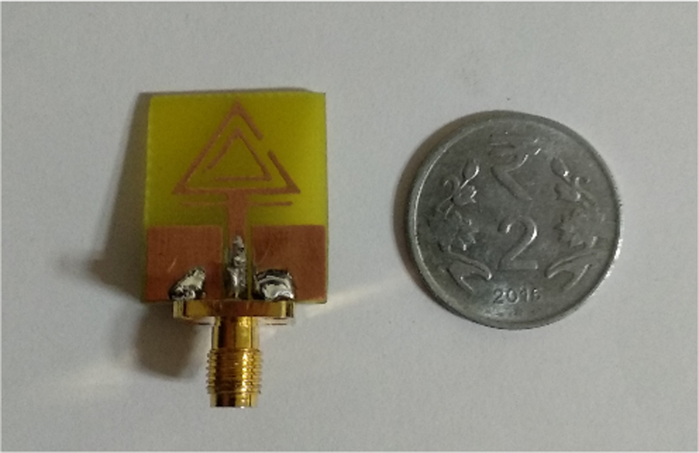
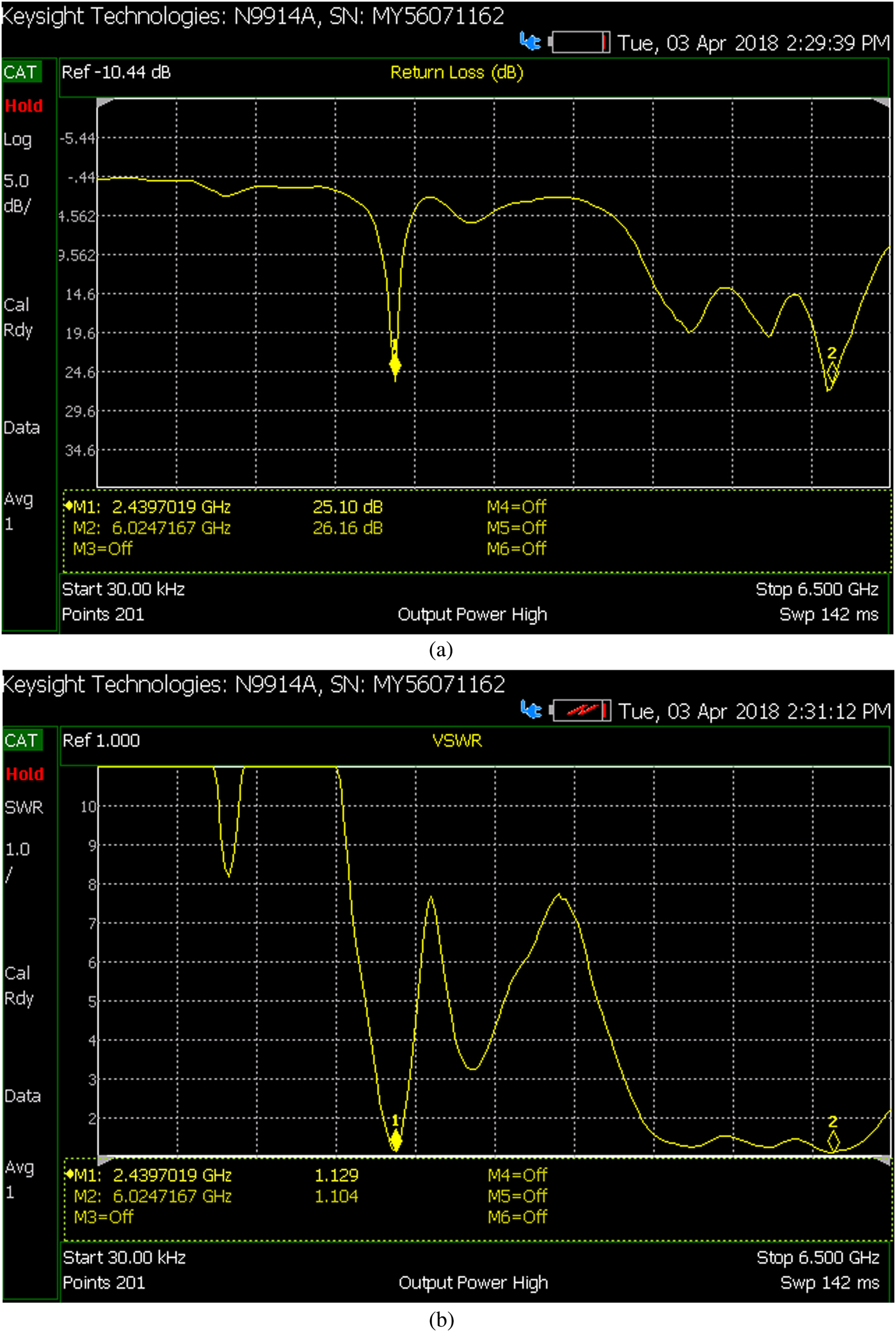
Measurements of various parameters of the antenna such as reflection coefficient, VSWR, and impedance bandwidth are done using Keysight N9914A vector network analyzer. Figure 11 shows the fabricated prototype of the proposed antenna comparative to 2 rupees Indian coin with diameter 25 mm. Figure 12 shows the snapshots of the measured return loss and VSWR on the Keysight N9914A vector network analyzer. Figure 13 shows the measured and simulated reflection coefficient (dB) characteristics of the proposed antenna simultaneously. Both the measured and simulated results match fairly well. From Fig. 13 it is clear that the antenna shows the measured bandwidth of 160 MHz (2.34–2.50 GHz) at the lower-frequency band and 1.97 GHz (4.45–6.42 GHz) at the upper-frequency band covering the desired WLAN frequency spectrum.

Fig. 11. Fabricated prototype of antenna.

Fig. 12. Measurement of (a) Return loss (b) VSWR on Keysight N9914A vector network analyzer.

Fig. 13. Measured and simulated reflection coefficient.
Conclusion
A metamaterial inspired, CPW-fed antenna has been designed, fabricated, and tested. It has been observed that use of metamaterial unit cell in designing the antenna to operate at desired band led to size miniaturization nearly by 2.5 times compared to the conventional triangular patch. Dual-band characteristics have been observed at 2.45 and 5.45 GHz operating frequencies with a gain of 1.9–2.41 dB and 2.2–2.5 dB, respectively. The two bands are originated from the metamaterial used in the antenna consisting of two triangular split rings and impedance matching is achieved using open-circuited stub. The measured bandwidth obtained at the two bands is 160 MHz (2.34–2.50 GHz) and 1.97 GHz (4.45–6.42 GHz), respectively. Nearly, omnidirectional radiation patterns are observed at both frequencies, hence showing a monopole antenna response. The experimental results have a good agreement with the simulated results. Thus the proposed antenna supports 2.4/5.2/5.8 GHz WLAN bands within a compact geometry which offers a wide range of application in wireless communication systems.
Author ORCIDs
Priyanka Jain, 0000-0003-4416-3904
 Priyanka Garg was born in Dehradun, India. She received her B.Tech. degree (Electronics & Telecommunication Engg.) in 2013 from Uttarakhand Technical University, Uttarakhand, India, and M.Tech. (Digital Signal Processing) in 2016 from G.B. Pant Engineering College, Pauri, Uttarakhand, India. She is currently pursuing Ph.D. from Delhi Technological University, Delhi. Her research is in the area of metamaterial-based microwave components.
 Priyanka Jain has received her Ph.D. in Signal Processing and is currently working as an Assistant Professor, in Department of Electronics and Communication Engineering, Delhi Technological University, Delhi, India since 2011. She received her B.E. degree (Electronics & Telecommunication) from Amravati University, Maharashtra, India, in 1998 and M.Tech. (Microwave Engg.) Delhi University, India. From 2001 to 2002, she worked as Lecturer at Guru PremSukh Memorial College of Engineering (GGSIP University), Delhi, India. From 2002 to 2011 she worked as Lecturer at India Gandhi Institute of Technology, New Delhi. Her teaching and research are in signal processing, analog electronics, and microwave engineering. She has published many articles in international and national journals in fields of signal processing, microwave and communication, noise receivers.