


INTRODUCTION
The Stonehenge World Heritage Site Landscape Project was established by English Heritage in 2008 to provide fresh and up to date information for the proposed new Visitor Centre and to assist, support, and complement the work of the various universities that had become involved in research within this landscape during the first decade of the century. It addressed a number of issues highlighted in the Stonehenge WHS Research Framework (Darvill Reference Darvill2005, 126–36) and not least the need for plans of the earthworks (Bowden et al. Reference Bowden, Barber, Field and Soutarin press). In so doing it has allowed a re-evaluation, of the traditional evidence and, in addition, shed new light on a number of aspects that help place Stonehenge itself in a better spatial, chronological, and historical context. The Project brought to bear an integrated array of non-invasive survey techniques, including earthwork analysis, geophysics, laser scanning, and aerial survey, together with documentary and archive research. All monuments in the World Heritage Site with a visible surface component were investigated, including the Greater Cursus and all the major barrow cemeteries, but excluding Durrington Walls henge enclosure which was recently comprehensively investigated by the Stonehenge Riverside Project, and Vespasian’s Camp hillfort where there were access problems. Results of the work at each site along with details of the methodology used are available for download in the English Heritage Research Department Research Report Series (available online at http://www.english-heritage.org.uk/publications/research-reports) and readers are referred to these reports for a fuller account. A synthesis of the collected field evidence and a full outline of the project will be presented elsewhere (Bowden et al. in press), while outstanding questions, not least those highlighted by the present work, are the subject of a revised Research Agenda currently in preparation. The present paper is concerned purely with the prehistoric periods and deals specifically with new data relating to Stonehenge itself and its immediate landscape setting (Fig. 1).

Fig. 1 Stonehenge: the location of the Stonehenge World Heritage Site boundary (dashed line) with the ‘triangle’ incorporating the English Heritage Guardianship area around the stones highlighted. ©English Heritage. Height data: Licensed to English Heritage for PGA, through Next Perspectives™.
While the stones have provided a focus for excavation and received much academic consideration, less attention has been given to the earthworks and to relationships and associations with the nearby barrow cemetery. It is surprising that earthwork analysis of individual monuments within the whole World Heritage Site (WHS) had not been carried out in most cases, and cartographic description relied upon revisions of early Ordnance Survey mapping. Indeed, at Stonehenge itself, the depiction of the earthworks for the major volume that published the 20th century excavation campaigns was of necessity taken from an Office of Works survey carried out in 1919 (Cleal et al. Reference Cleal, Walker and Montague1995, 22). On the other hand excavation during the 20th century was quite intensive, with major campaigns by William Gowland (Reference Gowland1902), Col. William Hawley (Reference Hawley1921–Reference Hawley1926; Reference Hawley1928) and Richard Atkinson (Reference Atkinson1979) resulting in about half of the site being trenched. The stones themselves have been surveyed on a number of occasions, notably by John Wood (Reference Wood1747) and Flinders Petrie (Reference Petrie1880) whose numbering system is retained here (Fig. 2), but most recently in 1990 by M. J. Rees & Co for English Heritage (English Heritage Archives, Swindon) and the latter data, checked by survey grade GPS, has been reused here. During the early 1990s both magnetometer and resistivity surveys were carried out (Payne Reference Payne1995) alongside a photogrammetric survey (Bryan & Clowes Reference Bryan and Clowes1997). Nevertheless, the current project took the opportunity to revisit the geophysics results within the ‘triangle’ (i.e. the land in the angle of the A303 and A344 roads limited by the north–south Larkhill by-way in the west) and, in particular, to introduce the use of ground penetrating radar (GPR; Linford et al. Reference Linford, Linford and Payne2012). Additionally, both the ground surface and stones themselves were recorded by laser scanning and in the latter case this was supplemented by photogrammetric recording of the upper surfaces of the lintels and freestanding uprights; the stones were thus recorded in unprecedented detail (<0.5 mm resolution) and will be considered separately in part 2 of this report (Field et al. Reference Field, Linford, Anderson-Whymark, Barber, Bowden, Linford and Toppingforthcoming).

Fig. 2 The central part of Stonehenge with stones mentioned in the text numbered according to Petrie’s (Reference Petrie1880) system and with areas of 20th century excavations highlighted. ©English Heritage.
Aside from Stonehenge itself, the ‘triangle’ contains a small cemetery of barrows (Amesbury 4–11) all but one of which lie to the west of the stones with one (Amesbury 10a) formerly identified as a long barrow (Fig. 3). Cutting across the north-east angle of the triangular field is the linear feature known as the Palisade Ditch. To the west of the north–south by-way, lie further barrows (Amesbury 1–3, 14, 15), one of which produced the ‘Stonehenge Urn’, though the distance between the groups is considerable, and the latter are not considered here. The other sites and features are discussed below as far as possible in chronological order. Those of later date within the ‘triangle’ and on the wider area of Stonehenge Down, including earthwork remnants of the Stonehenge Aerodrome, are discussed elsewhere (Bowden et al. Reference Bowden, Barber, Field and Soutarin press; Barber Reference Barber2014b).

Fig. 3 Earthworks within the ‘triangle’; including round barrows Amesbury 4–11 well as 10a which was formerly identified as a long barrow. ©English Heritage. Height Data: Licensed to English Heritage for PGA, through Next Perspectives™.
Aerial survey of the complete World Heritage Site (WHS) and its immediate surroundings was undertaken in 2001 at a scale of 1:10,000 as part of English Heritage’s National Mapping Programme (NMP), with a summary report being published at the time (Crutchley Reference Crutchley2002). Aspects of the mapping have been discussed elsewhere (Barber et al. Reference Barber, Grady and Winton2003: Barber Reference Barber2011), while initial analysis of the lidar cover was described by Bewley et al. (Reference Bewley, Crutchley and Shell2005). Within the current project the main use of the aerial photographic record and documentary sources has been to examine the impact of agriculture, military activity and, for Stonehenge itself, not least, invasive archaeology and restoration (Bowden et al. Reference Bowden, Barber, Field and Soutarin press: Barber Reference Barber2014a; 2014b).
Cultivation is not considered to have taken place within the Stonehenge earthwork enclosure and to an extent the presence of the enclosure ditch will have discouraged it, but the impact on surface features in the rest of the ‘triangle’ may have been quite considerable, particularly on the barrow group. Early estate maps and documents along with Ordnance Survey mapping indicate that much of the area to the west suffered during the 19th and 20th centuries (Field & Pearson Reference Field and Pearson2011; Long Reference Long1876: Bowden et al. Reference Bowden, Barber, Field and Soutarin press) and this, in turn, influenced the route of trackways across the downland and was in part responsible for their concentration around Stonehenge itself (Field & Pearson Reference Field and Pearson2011, 13–14, 37–9). Documentary sources record the increasing conversion of downland from pasture to arable from the 17th century onwards, albeit often on a temporary basis (Bowden et al. Reference Bowden, Barber, Field and Soutarin press: Barber Reference Barber2014b; Field & Pearson Reference Field and Pearson2011, 32, 37–9; RCHM(E) 1979a, xvi–xviii; Bond Reference Bond1991). Cultivation from Fargo/Virgo Cottages extended east and south across Stonehenge Down as far as the line of the present A303. William Long described how ‘cultivation of the down around Stonehenge is gradually closing in upon it, and on the west side had already resulted in the obliteration’ of Amesbury 4–10a. A Mr Edwards of Amesbury had informed him that the largest mound had ‘been deliberately degraded to its present low elevation that it may the more easily be ploughed over’, while the other barrows in the group ‘will soon have altogether disappeared’ (Long Reference Long1876, 186, 198). The close proximity of both Fargo Cottages and arable to Stonehenge can be seen in some of the photographs taken by the architect John Jenkins Cole in the summer of 1881 (Fig. 4: English Heritage Archives): the proximity that provoked William Long to comment that ‘it is to be hoped that our grand-children will not have to look for Stonehenge in a field of turnips’ (Long Reference Long1876, 186).

Fig. 4 Photograph taken by J.J. Cole in August 1881 looking south-west from Stonehenge and illustrating the proximity of encroaching cultivation. The track beyond the stones has been curtailed by ploughing. In the distance are Fargo, or Virgo, Cottages and associated farm buildings, constructed c. 1847 and demolished in the Spring of 1918. Photo ©Reproduced by permission of English Heritage Archives
PERIGLACIAL GEOGRAPHY AND HOLOCENE LAND SURFACE
While Charles Darwin’s work, probably on Stones 8, 9 and 12 or 14, emphasised how the soil profile was raised by earthworm activity leaving the stones partially buried (Darwin Reference Darwin1881, 154–6; Field & Pearson Reference Field and Pearson2010, 43–4), Richard Atkinson’s (Reference Atkinson1957) investigation into worms and weathering indicated that the land surface at Stonehenge had been truncated quite considerably as a result of dissipation of the chalk sub-soil over some 4000 years. Groube and Bowden (Reference Groube and Bowden1982, 16–18), however, subsequently demonstrated that such truncation across the chalk downland was in great part a result of recent cultivation. Despite the anticipated truncation of the chalk outside the enclosure, the new surveys provide some indication of the state of the former land surface. The GPR reveals a series of north-east trending, gently inclined anomalies recorded at an approximate depth of 0.9 m downwards (Fig. 5). These reflections begin at too great a depth to relate to recent intervention and cannot be the signature of surface trackways (for trackways see Bowden et al. Reference Bowden, Barber, Field and Soutarin press: Field & Pearson Reference Field and Pearson2011). All share a similar inclination, dipping along a north-west to south-east strike on a comparable orientation to the periglacial features recently identified along the Avenue (Parker Pearson Reference Parker Pearson2012, 242–4). Similar anomalies have also been recorded recently in the GPR data from the wider WHS landscape collected by the Ludwig Boltzmann Institute (Baldwin Reference Baldwin2010; Gaffney et al. Reference Gaffney, Gaffney, Neubauer, Baldwin, Chapman, Garwood, Moulden, Sparrow, Bates, Löcker, Hinterleitner, Trinks, Nau, Zitz, Floery, Verhoeven and Doneus2012), and it seems most likely that they represent a geological interface, perhaps concentrated flint or marl seams embedded within the underlying chalk. It may be relevant that the Andover soils that cover the area are said to have a tendency to occur over ‘striped soil patterns’ (Soil Survey 1983).

Fig. 5 Stonehenge: a selection of GPR amplitude time slices; the arrows mark the periglacial features recorded at approximate depths of between 0.9 m and 1.78 m. ©English Heritage.
It is evident from excavation section drawings that the surface of the chalk at Stonehenge is not level and may rise in the south-eastern part of the stone settings. The chalk revealed in Gowland’s trench adjacent to Stone 55 rose markedly from one end of the trench to the other (Gowland Reference Gowland1902, 52, fig. 12), while Hawley (Reference Hawley1921, 22) noted that the natural chalk rose higher behind Stone 7. Here the surface expression of an ephemeral mound, 0.25 m high, survives on the surface as a topographic feature (Fig. 2). This measures some 15 m wide with a basal plinth that appears to be surmounted by a secondary tump and its west side is demarcated and emphasised by an irregular but c. 5 m wide shallow hollow or depression, no more than 0.25 m deep that is best depicted on the contour plot (Fig. 6). In the north-east, a rebate in the 102.25 m contour that the stones in the sarsen circuit cut across, provides emphasis. The mound was the subject of extensive enquiries to establish whether it is of recent or historical date, but photographs of Gowland’s site caravan parked upon it during the excavations of 1901 indicate that it was not the result of 20th century excavation spoil, or other disturbance, while a number of artists (and others) who produced sketches, watercolours, etc, of Stonehenge during the 18th and 19th centuries depicted its uneven or undulating surface. Additionally, the course of the Y and Z Holes appear to respect the low mound (see below) and it would therefore appear to pre-date them. Crucially, the natural interface between pits visible in the cutting made by Darvill and Wainwright (Reference Darvill and Wainwright2009, fig. 7; T. Darvill pers. comm.) indicates that the chalk lay close to the surface here and we therefore tentatively conclude that the mound is a surface expression of the geology rather than a structure of cultural origin.

Fig. 6 Stonehenge: the mound within the sarsen circle: terrain model and contours from field survey. ©English Heritage.

Fig. 7 Stonehenge: high Amplitude GPR reflectors. Numbers refer to anomalies mentioned in the text and taken from the sequence in Linford et a.l 2012. ©English Heritage.
Why such a feature occurs at this point is not clear, given that, as noted above, the chalk is highly susceptible to weathering and it is unusual for a natural mound to remain on the Wiltshire chalk (Newall’s mound set to the north-east along the Avenue 20 m south of the elbow, while set over a solution hollow, lies at a former field edge and may be related to the boundary – see Field et al. Reference Field, Bowden and Soutar2012). Elsewhere, earthen structures are known to retard weathering at, for example, Horslip long barrow (Ashbee et al. Reference Ashbee, Smith and Evans1979, 211) and it might be considered that the Stonehenge Layer contributed here. While of considerable thickness (Darvill & Wainwright Reference Darvill and Wainwright2009), however, that is more extensive across the area and not confined to the area of the mound. The only two locally occurring weather retardant materials are flint and sarsen and, since local flint is only thinly distributed here, in the absence of alternatives sarsen may have to be considered as the preserving agent. The circumstances determining natural sarsen emplacement have unfortunately seen little research and, Darwin’s observations notwithstanding, the degree to which they may rest on the surface or sink into it is unknown: both can be observed on Fyfield Down and additionally a link with solution hollows is recorded (Clark et al. Reference Clark, Lewin and Small1967; Bowen & Smith Reference Bowen and Smith1977). Several authorities have suggested that the sarsens were sourced from the area of Stonehenge or somewhere closely adjacent (see below). Darvill et al. (Reference Darvill, Marshall, Parker Pearson and Wainwright2012, 1029) have recently suggested that some stone was probably present on site at the outset; notably the massive cone-shaped Heelstone as it has been considered to have been extremely difficult to move (Johnson Reference Johnson2008, 121), an observation supported by measurements taken from the laser scan data which demonstrates that it is the heaviest stone on site (Abbott & Anderson Whymark Reference Abbott and Anderson-Whymark2012; Field et al. Reference Field, Linford, Anderson-Whymark, Barber, Bowden, Linford and Toppingforthcoming).
EARLY FEATURES
Ground Penetrating Radar has revealed the presence of several significant anomalies that lie in an area to the north-west of the Stonehenge enclosure ditch (Linford et al. Reference Linford, Linford and Payne2012) and which are sealed at an estimated depth of between 1.3 m and 1.6 m in a location beyond earlier earth resistance coverage and in an area too disturbed to produce any useful data by magnetic survey (Fig. 7, gpr 63, 64). Although speculative, some comparison of these can be made with the size, spacing, and orientation of the Mesolithic pits excavated in the former visitor centre car park to the north (Cleal et al. Reference Cleal, Walker and Montague1995, 42–7), but as with other anomalies greater certainty will only come with direct intervention.
Amesbury 10a and the pre-barrow features beneath Amesbury 6–9
Elsewhere within the ‘triangle’ there are other features that potentially pre-date the Stonehenge enclosure and/or the stone settings, or are contemporary with them. One of these is a mound (Amesbury 10a – parish numbers were first allocated by Goddard (1913) and added to by Grinsell (Reference Grinsell1957)) identified by Sir Richard Colt Hoare and depicted on Philip Crocker’s plan (Hoare Reference Hoare1812, 128). Subsequently catalogued as a long barrow, it remains visible as a slightly oval earthwork (Fig. 8), 24×20 m and just 0.2 m high, located c. 250 m to the west of Stonehenge. No side ditches are visible and none was recorded by geophysical survey in 1993–4 (Payne Reference Payne1995, 498) or from the air by the National Mapping Programme. Hoare cut a trench into it but his intervention resulted in ‘no discovery’, meaning that a burial deposit was not discovered. Such an outcome would not be unusual for a long barrow but, in this case, the existing form of the mound appears as a simple ovoid. It was not depicted alongside the other barrows of this group on the First or Second Editions of the OS 25 inch map published in 1877 and 1901 respectively, and Goddard (1913–Reference Goddard14, 165) simply catalogued it as a ‘small long barrow opened by Hoare’ rather than recording contemporary field observations. Soon after, Maud Cunnington (Reference Cunnington1914, 408) noted that it was ‘practically ploughed out’, which is not surprising given the extensive cultivation in the area (above). The nature of this feature can now only be resolved by excavation.

Fig. 8 Earthwork survey of barrows in the south-west of the ‘triangle’ showing Amesbury 4–10a. ©English Heritage. Height Data: Licensed to English Heritage for PGA, through Next Perspectives™.
To the south-west of the Stonehenge enclosure lies a group of seven further barrows (Fig. 8: Amesbury 4–10) of which little is known beyond some ambiguous antiquarian accounts (Stukeley Reference Stukeley1740, 45; Hoare Reference Hoare1812, 127–8; and see Field & Pearson Reference Field and Pearson2011). Like Amesbury 10a, these have suffered from agricultural activity but also the dumping of rubbish from the aerodrome in late 1917–early 1918 which may have obscured archaeological detail (Memo, Charles Peers to Lionel Earle, 22 January 1918 – The National Archives (TNA) WORK 14/214). Despite this, they still survive as earthworks (the mounds themselves are likely to be of Early Bronze Age date and are reported below), but geophysical survey in 1993 (Payne Reference Payne1995, 497) revealed that several masked earlier activity. Recent enhancement of the fieldwork data, using higher density caesium magnetometer survey, together with GPR (Linford et al. Reference Linford, Linford and Payne2012), has provided greater clarity and extra detail of these earlier phases (Fig. 9).
Beneath Amesbury 7
The geophysical plot of Amesbury 7 (Fig. 9) depicts an area defined by an oval ditch and oriented north to south. Causeways occur through the ditch at the southern end similar to those in Cranborne Chase-style long barrows. Thickthorn Down (Drew & Piggott Reference Drew and Piggott1936) and Wor Barrow (Pitt Rivers Reference Pitt Rivers1898, 60–122) in Dorset, as well as North Marden in Sussex (Drewett Reference Drewett1986) and Sheer Barrow on Figheldean Down, Wiltshire (McOmish et al. Reference McOmish, Field and Brown2002, fig. 2.13) all display the characteristic causeways at one end albeit in slightly different configurations. At a modest 13 m in length this is shorter than those examples, though little less than, for example, Alfriston in Sussex, where the mound was estimated to reach 14.5 m and the excavator indicated that before excavation it appeared to be a round barrow (Drewett Reference Drewett1975). Similarly, the earlier mound at Wayland’s Smithy was just 16×8 m and like Amesbury 7 is oriented just east of north–south (Atkinson Reference Atkinson1965, 127; Whittle Reference Whittle1991, 57). Reference to the variety of long barrow sizes and forms in Hampshire (RCHM(E) 1979b, figs 2–5) as well as non-Neolithic oval forms serves to emphasise the difficulty in sub-dividing the class and for the moment traditional terminology is employed (cf Darvill Reference Darvill2005, 129).
The attribution of Amesbury 7 as a small Long Barrow needs to be tested, as both its cardinal axis and topographical position are unusual. However, in these respects it is not alone in the Stonehenge landscape, for a similar small example, Wilsford 13, at the heart of the Normanton Down cemetery less than a kilometre to the south is also oriented north–south and positioned across the contours (Barrett & Bowden Reference Barrett and Bowden2010, 14–15, 33), though unfortunately surface details of its ditch have been obscured by cultivation. Further examples include Woodford 2, to the south-west, where the mound must have originally been in the region of 15 m in length and is also aligned north–south across the contours (Harding & Gingell Reference Harding and Gingell1986), while a plough-levelled example, Amesbury 140, is situated a little west of Vespasian’s Camp. Like the example at Stonehenge, a large now-levelled round barrow once impinged on it and in both cases, as well as that on Normanton Down, the long barrow formed an integral part of a later cemetery. Hoare (Reference Hoare1812, 128) found Amesbury 7, like Amesbury 10a, ‘unproductive’, suggesting that he found no burial.
Beneath Amesbury 6
Within the peripheral circular ditch of the mound of Amesbury 6 lies an oval ditch which, being sealed by the later mound, is indicative of an earlier phase of construction activity (Figs 9 & 10). This inner ditch appears to be formed of conjoined pits with causeways or entrances in the north-west and south-east and given these gaps it is likely to indicate the former presence of a henge-like monument. Disturbance to the north-east ditch may be the result of Hoare’s (Reference Hoare1812, 128) trenching. The space between the two ditches may mark the position of an external bank which could actually be sealed within the surviving mound matrix. Comparison might be made with the similar response revealed recently during the survey of Amesbury 50 (Gaffney et al. Reference Gaffney, Gaffney, Neubauer, Baldwin, Chapman, Garwood, Moulden, Sparrow, Bates, Löcker, Hinterleitner, Trinks, Nau, Zitz, Floery, Verhoeven and Doneus2012; and see Amadio & Bishop Reference Amadio and Bishop2010, 8–9, 22–4; Linford et al. Reference Linford, Linford and Payne2012; Darvill et al. Reference Darvill, Lueth, Rassman, Fischer and Winkelmann2013), but more particularly with the pit setting at Site 1 at Dorchester on Thames (Atkinson et al. Reference Atkinson, Piggott and Sanders1951, fig 4; Whittle et al. Reference Whittle1992), although there an entrance gap was only present in the north-west. There, however, a linked series of pits appears to have formed an encircling ditch associated with Mortlake Ware. In certain respects comparison can also be made with the excavated oval pit circuit at Monkton-Up-Wimborne in Dorset where more widely spaced pits enclosed an area c. 35 m across with a wide entrance gap at either end (Green Reference Green2000, 77–8: French et al. Reference French, Lewis, Allen, Green, Scaife and Gardiner2007, 115). Finds within the upper filling of those pits included a kite-shaped arrowhead and Peterborough Ware potsherds indicating a Middle Neolithic date for its later phase of use and it is worth recalling the surface finds of Peterborough Ware along with chisel and oblique arrowheads found beyond the ‘triangle’ to the west during fieldwork during the 1980s (Richards Reference Richards1990, 35, figs 26 & 158) and chisel and oblique arrowheads found there in a recent intervention (Parker Pearson et al. Reference Parker Pearson, Allen, Bayer, Casswell, Chan, French, Garwood, Nunn, Pitts, Pollard, Pullen, Richards, Richards, Robinson, Rylett, Shaw, Teather and Thomas2008, 109, 114). Whether the Amesbury 6 configuration originated during the same period cannot be ascertained by non-invasive survey but, like Amesbury 7, this site may well pre-date – or be contemporary with – the Stonehenge enclosure earthwork.

Fig. 9 Caesium magnetometer survey, 2010, over Amesbury 5–10 superimposed over the previous Fluxgate gradiometer survey of the Triangle, 1994. Inset: Amesbury 5–9. Caesium magnetometer plot (left) and GPR data (right) from between 6.0 ns and 7.2 ns (0.3 – 0.36 m). ©English Heritage

Fig. 10 Amesbury 6: left – detail from the 2010 caesium magnetometer plot; right – combined new earthwork survey and interpretation of geophysical anomalies. ©English Heritage.
Beneath Amesbury 8
In contrast to its apparently ditchless surface appearance, the mound of Amesbury 8 has been revealed by geophysical survey to be juxtaposed over an irregular, elongated, and probably segmented ditch with a possible entrance gap in the south-east and a second in the south (Fig. 9). The ditch is discontinuous and, like Amesbury 6, might originally have comprised a series of pits that were in part later conjoined. Posts/pits complete the circuit and may mark an earlier phase. Similarities with Sites IV and V at Dorchester on Thames are evident and, given the lack of obvious chronological precision, Peterborough Ware pottery present at the latter sites may provide some relative indication of date for Amesbury 8. Alternatively, it might be compared with similar structures on Wyke Down, Dorset (Green Reference Green2000, 87–9) which were associated with Grooved Ware, indicating a date within the 3rd millennium (Garwood Reference Garwood1999, 152), or with structures such as the segmented ring-ditch at Barrow Hills, Radley (Barclay & Halpin Reference Barclay and Halpin1999), where Beaker potsherds were recovered from a late stage of the silting. An irregular and recut segmented ring-ditch of similar size to Amesbury 8 was excavated on Normanton Down, much closer than these (Smith Reference Smith1991, 13–18). While associated with Beaker burials, the ditch contained pottery ranging from the early Neolithic and unfortunately remains undated.
Beneath Amesbury 9
The new caesium magnetometer survey has revealed additional detail beneath Amesbury 9 (Figs 9 & 11), clarifying some anomalies that were only hinted at in the previous fluxgate data. The site now appears to be defined by an irregular and segmented ovoid ditch, sharply angled in the south. The southern arc of this is broadly continuous, although highly variable in anomaly width (<1–2.5 m) and magnetic character with a distinct corner at its southernmost point leaving the south-east facing section almost straight. However, the northern arc is composed of four discrete pit-type responses with each anomaly ~2.5 m in diameter. Three of these pits form a line, separated from each other by a distance similar to their diameter. The fourth is positioned to the east and has the weakest peak field strength. Between these is a discontinuous and indistinct narrow anomaly less than a metre wide, which might suggest the existence of a conjoining ditch or palisade.

Fig. 11 Amesbury 9: left – detail from the 2010 caesium magnetometer plot; right – combined new earthwork and interpretation of geophysical anomalies. ©English Heritage.
Enclosed by this outer circuit is a second oval of 22–24 post-pit anomalies, visible in both the magnetic and GPR datasets, each between 0.5 m and 1 m in diameter, separated by gaps of 1–2 m. It is difficult to determine whether gaps exist in the north-west and south-east due to lack of clarity amid a complex of features. To the south-west there is evidence of a third concentric alignment comprising at least four post-pit anomalies, each ~0.5 m in diameter, although there is no sign of others to suggest that they were part of a more complete circuit. The GPR data provides a similar level of detail and largely confirms the series of small, post-pit anomalies immediately inside the ditch circuit. The limited vertical extent of these anomalies may well be indicative of a response from a thin, compacted basal layer, rather than the full profile of the pit. Compared to the magnetic data the more pronounced post-pit anomalies to the north-east generally correspond to low amplitude GPR responses, and the more subtle response to the south-west with mainly high amplitude reflectors. A scatter of high and low amplitude GPR anomalies within the central area of the site are difficult to interpret and may result from Early Bronze Age use, or possibly, be due to more recent antiquarian intervention.
Assuming the ditch and pits to be broadly contemporary it seems unlikely that ditch spoil was placed within the enclosure; taken together the new survey evidence suggests that, as Payne (Reference Payne1995, 498) inferred, Amesbury 9 might have been a henge-like monument not unlike the smaller of the Wyke Down henges. The similarity to site 1 at Dorchester on Thames (Atkinson et al. Reference Atkinson, Piggott and Sanders1951, fig 4: Whittle et al. Reference Whittle1992) is striking. The latter is likely to represent several phases with the pits containing Abingdon Ware, while the ditch is associated with Mortlake Ware. While its precise chronological position and phasing will only be established by excavation, the proximity of Amesbury 9 to Stonehenge means that the development of ceremonial activities on Stonehenge Down can now be considered in a fresh light.
None of these structures has been dated independently and of course some caution is required as it is evident that there has been remodelling and re-use up to the point when they were mounded over. Nevertheless, the parallels here appear to be with monuments that comprise henge-like affinities and/or fall neatly within Kinnes’s (Reference Kinnes1979) Neolithic enclosed cemetery/ring-ditch continuum. In this respect it is worth recalling that the pit/segmentally cut Stonehenge enclosure ditch was also assigned to this category, although more recently considered to fall into a class of ‘formative’ henges (Harding Reference Harding2003, 13; Burrow Reference Burrow2010). It is clear that far from being isolated, Stonehenge may have been a component part in a ceremonial and funerary area within its immediate environs, with origins and traditions potentially traceable to the earlier Neolithic. Initially at least the focus of activities may have been around one or more of these other monuments.
North and South ‘Barrows’
Ever since Richard Atkinson recorded the presence of bluestone chips in its bank, and Thom and Atkinson cut a small trench to investigate the expected position of the stone-hole for Station Stone 94 (Cleal et al. Reference Cleal, Walker and Montague1995, 273, 276), ‘North Barrow’ has been considered to be a relatively late feature in the Stonehenge sequence. Cleal and colleagues assigned it to Phase 2 on account of similarities with the ditch surrounding the Heelstone and to the evidence from the ‘South Barrow’. Careful study of the earthworks, however, reveals that the ‘North Barrow’ does not overlie the enclosure bank to complete a circuit (Fig. 12), and the early aerial photographs taken by Lt Sharpe from a balloon in 1906 (Fig. 13) strengthen the observation that the ‘North Barrow’ earthworks probably pre-existed the enclosure earthworks, for the enclosure bank can clearly be seen as continuous and unbroken. Whether this sequence can be proven is now difficult to ascertain from the disturbed surface evidence alone, for a succession of trackways and pathways have cut through and destroyed the greater part of the interface. Comparison of Sharp’s photograph with a second, vertical, example taken on the same date (Fig. 14) is interesting. This appears to show a low bank with an internal ditch, the latter distinctly circular and visible clearly as an arc of more prominent grass growth among the more generally parched vegetation. The earth resistance survey also indicates that the ditch is interrupted by the enclosure bank (Fig. 15), although the GPR (Fig. 7) is unclear about the relationship. In addition, the configuration of the outer scarp of the enclosure bank unusually – and in contrast to the rest of the circular enclosure – incorporates two straight lengths of bank (Fig. 12) which may have been influenced by the presence of an earlier circular structure. Earlier accounts support this observation. Philip Crocker’s survey carried out for Sir Richard Hoare also depicts the earthworks in this way (Hoare Reference Hoare1812, facing p. 143) and Hoare commented that the ‘North Barrow’ was probably constructed before the enclosure ditch was dug (Wiltshire Museum Cunnington MSS: Hoare Reference Hoare1812, 145). Similarly, William Long concluded that the Stonehenge enclosure ditch ‘cuts through the ring of a low barrow on the northwest side’ (Long Reference Long1876, 54). Considering these observations, it might be tentatively suggested that the ‘North Barrow’ is an earlier feature.
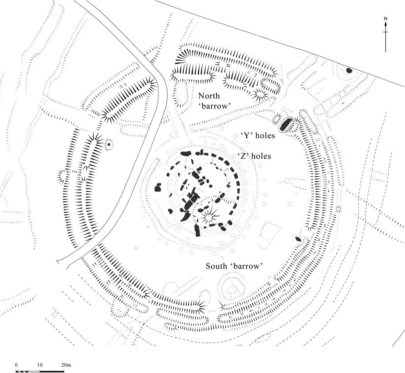
Fig. 12 Stonehenge: the new earthwork plan showing the remaining portion of the ‘north barrow’ bank and ditch which does not cross the enclosure bank. ©English Heritage.

Fig. 13 Stonehenge: oblique view by 2nd Lt P.H. Sharpe RE, taken from a Royal Engineers reconnaissance balloon in the summer of 1906. From Archaeologia 1907. Reproduced by permission of the Society of Antiquities of London.

Fig. 14 Stonehenge: original 1906 print of a vertical view by 2nd Lt P.H. Sharpe RE, one of five aerial views taken by him in the summer of 1906. Reproduced by permission of the Society of Antiquities of London.

Fig. 15 Stonehenge: earth resistance plot, 1994. ©English Heritage.
As a discrete field monument, the remains of the ‘North Barrow’ earthwork today comprise a ditch within an encircling bank, with an apparently level interior, and it might therefore fall into the category of small ring-ditch. However, it is noteworthy that the earliest accounts of both ‘North and ‘South Barrows’ describe them rather differently. Stukeley recorded the existence of ‘two remarkable cavities’. His illustration (1740, 16, table 9) shows the southern cavity drawn with vertical hatching surrounded by a ditch and evidently overlain or curtailed by the enclosure bank. Stukeley’s contemporary, John Wood, who surveyed the site in 1747 and published his field drawing of the stones along with survey measurements, left his station rods in position so that others could check them. His observations therefore might be considered with some seriousness. Like Stukeley, he commented on the circles (Wood Reference Wood1747, 44, 50), describing them as cavities rather than barrows, ‘one with a single Bank of Earth about it; and the other with a double bank separated by a ditch’. They were ‘compleat Works of themselves’, the depression measuring nearly 5 m in diameter and the feature as a whole about 12 m across, ‘each Pit is about Sixteen Feet [c. 4.9 m] diameter, and the banks that surround them increase the Diameter of each Work to about forty Feet [c. 12.2 m]’. The northern cavity was ‘further enlarged by a Ditch and a Second bank of earth’. Almost 25 years later, John Smith’s description (Reference Smith1771, 52) supports these accounts, referring to the features as two ‘circular holes encompassed with the earth that was thrown out of them; but they are now almost effaced by time’. If we accept these descriptions it implies that these earthworks have seen considerable modification at some later date.
It was Hoare (Reference Hoare1812, 144) who first described them as barrows, following Cunnington’s description of the northern example as a ‘small Druid [i.e. disc] Barrow’ (Wiltshire Museum Cunnington MSS Book 1, 13 letter to Hoare 18 December 1806) and noting that they were ‘only slightly elevated above the surface’. The attribution was commented on by Hawley (Reference Hawley1928, 174) who referred to the southern example as a ‘so called barrow’ (1923, fig. 1) and demonstrated that it was anything but; Cleal et al. (Reference Cleal, Walker and Montague1995, 26) concurred that they are not burial mounds.
The evidence from excavation brings further complexity and, to a degree, contrasts with that of field survey. Cunnington encountered a deposit of burnt bones in the northern ‘barrow’ and it has since been presumed that he may have discovered deposits associated with Aubrey Hole 46 which, if the spacing of others is projected, might be expected to lie on or beneath the central platform of the feature (Newall Reference Newall1929, 82; Cleal et al. Reference Cleal, Walker and Montague1995, 96). Atkinson cut a small trench across the ditch and part of the bank at a point where it almost met the enclosure bank but unfortunately did not extend it to test the relationship between the ‘barrow’ and the bank, nor that of the predicted Aubrey Hole 47. The ‘barrow’ ditch proved to have a V-shaped profile and among items recovered from secondary silts were sherds of Iron Age and Romano-British pottery, while bluestone fragments were found in both the bank and ditch (Cleal et al. Reference Cleal, Walker and Montague1995, 276–80). A small trench partially excavated into the north-west quadrant of the central platform by Thom and Atkinson in 1978 (ibid., 273) demonstrated that the stone-hole encountered (Station Stone 94) was not central to the earthwork and was sealed by a considerable covering (0.6 m) of chalk lumps and humus enriched soil. That stone-hole is not the same thing as the 5 m diameter depression noted by Wood and others, but it might be presumed that herein lies the solution. However, scrutiny of the trench section drawing makes things clearer, for it would appear that the hollow had been filled and levelled with over 0.5 m of soil sometime between the observation of Smith in Reference Smith1771 and descriptions by Hoare in 1810. The presence of three projected Aubrey holes, two in the ditch and one on the platform introduces additional complexity, particularly if they originally held stones or posts, which would then have needed to be dismantled if the ditch were cut at a later date.
The South ‘Barrow’ is rather different and the field survey supports the observation of Hawley that it is later than the enclosure bank, although it must be stressed that surface observation here is of Hawley’s reconstructed feature and it is by no means clear to what extent the ditch now visible on the surface represents an original earthwork, so this interpretation has to be treated with caution. Lt Sharpe’s 1906 aerial photographs demonstrate that prior to excavation the proud profiled earthwork was not visible (Figs 13 & 14). The surface evidence is currently of a surrounding ditch that forms a D-shaped plan and contrasts with the profile of the North ‘Barrow’; it also differs in that there is no external bank. On excavation Hawley (Reference Hawley1922, 48) depicted the ditch as V-shaped in profile (but see his pl. viii, figs 1 & 2 which may indicate a recut). The level floor encountered consisted of a ‘yellow substance resembling chalk beaten fine and mixed with clay …’ up to 0.15 m thick and parts of the surrounding ditch was ‘covered with the same kind of compo as the floor’. Hawley considered that the feature was more likely to be a hut than a barrow. While the purpose and date of the ‘South Barrow’ remains difficult to determine, the recent discovery of Neolithic houses at Durrington Walls henge which had floors not dissimilar to those recorded by Hawley, has allowed Parker Pearson to re-appraise the evidence and conclude that this may indeed have been a building platform (Parker Pearson et al. Reference Parker Pearson, Cleal, Marshall, Needham, Pollard, Richards, Ruggles, Sheridan, Thomas, Tilley, Welham, Chamberlain, Chenery, Evans, Knusel, Linford, Martin, Montgomery, Payne and Richards2007; Reference Parker Pearson, Chamberlain, Jay, Marshall, Pollard, Richards, Tilley and Welham2009, 33–4; 2012, 310). If the ‘South Barrow’ was a building platform it would make sense of Hawley’s description of it cutting into the bank.
Scrutiny of the trench profile (Cleal et al. Reference Cleal, Walker and Montague1995, fig. 165) reveals that, like the ‘North Barrow’, this was covered by at least 0.5 m of soil and, consequently, the hollow described by antiquarians appears to have been filled and levelled at some point. Hawley did encounter a hollow although the size of it does not match the descriptions of the earlier observers. Initially he considered it to be the result of an earlier excavation (Hawley Reference Hawley1922, 48) – presumably that of Cunnington who, according to Hoare (Reference Hoare1812), found nothing – and later considered that it was a stone-hole (i.e. Station Stone 92; Hawley Reference Hawley1923, 15). Unfortunately the relationship of the stone-hole to the platform remains unclear, but there is an assumption that the stone-hole must have been dug through the platform otherwise it would not have been visible to the early observers. Similarly the floor material that lay over the ditch is curious, for it implies that the cutting of the ditch preceded not only the floor but potentially the stone-hole.
There is some additional complexity adjacent to the ‘South Barrow’ suggested by the GPR, comprising the presence of a slightly arced linear response extending to the north and an amorphous, sub-circular anomaly immediately to the west (Fig. 7). The previous earth resistance data show a diffuse area of increased background response that correlates with the GPR anomaly to the west and a discrete high-resistance anomaly immediately to the north, although the latter was subsequently tested and found to be an area damaged by rabbit burrowing (Payne Reference Payne1995).
In more recent times interpretation of these features has suggested that they are the product of excavations for two of the ‘the four stations’ – i.e. Station Stones 91–4. E. Herbert Stone considered that the ‘two mounds are sites which were at one time occupied by two stones which, with the pair remaining, formed a symmetrical group of four … the earth forming the mounds … would simply represent the spoil thrown out by excavations when the stones were removed’ (Reference Stone1924, 114, 116). It is evident, however, that in each case there are a considerable number of problems and several phases of activity to account for.
THE STONEHENGE ENCLOSURE
The Stonehenge enclosure survives as a well-defined earthwork comprising two banks separated by a ditch that describes a circle 102 m in diameter when measured between the internal lips. Much of the outer bank has been reduced by cultivation but was evidently largely extant in the 18th century as recorded by Wood (Reference Wood1747, 79). It is well preserved in the north where the proximity of the road may have discouraged tilling. Here it is of significant proportions and need not be envisaged as a counterscarp (Hawley Reference Hawley1923, 14; 1928, 52) despite the prevalence of this terminology (Cleal et al. Reference Cleal, Walker and Montague1995, 24). Geophysical survey in 1994 and again recently, emphasised that the width of the outer matched that of the internal bank and it was clearly once of substance (Linford et al. Reference Linford, Linford and Payne2012; Payne Reference Payne1995, 501). Its presence has certain implications in terms of the interpretation of the construction sequence, for notwithstanding the comments above, it is conceivable that the enclosure may have been defined initially by the outer bank, i.e. the standard ‘henge’ configuration, the inner bank being added later. Given the form of contemporary comparable monuments (Burrow Reference Burrow2010, fig. 11.2) that interpretation need not be pursued unduly, although it is eminently feasible, or even likely, that two or more phases of activity are represented by the enclosure earthworks and the recently recognised recut visible in Hawley’s section drawings of the ditch (Parker Pearson et al. Reference Parker Pearson, Chamberlain, Jay, Marshall, Pollard, Richards, Tilley and Welham2009, 29–30, pl. 18, fig. 2; 1923) serves to emphasise the point.
The form of the enclosure provides some evidence for this, as its character differs from west to east (Fig. 12). Both banks and the ditch are of wider proportions in the west than in the east. The western arc is relatively broad and flat-bottomed compared to that in the east (where it has, admittedly, been excavated leaving a different surface appearance). Similarly, the inner bank in the west is more substantial than that in the east which can be clearly seen in the digital terrain model (Fig. 16). This difference is also visible on the resistivity plot (Fig. 15). The changing character of the ditch was noted by Hawley who commented on the pit-like nature of the excavated chalk in the south, compared to the great segment that he had excavated in the east. Apart from a small trench excavated by Atkinson at a point where the trackway breaks through (Cleal et al. Reference Cleal, Walker and Montague1995), the western part of the ditch has not been excavated and it is unclear to what extent deposits and the presence of cultural material, particularly cremations, might differ from those in the east.

Fig. 16 Stonehenge: digital terrain model of earthworks set within a lidar background (outer area). ©English Heritage. (Lidar data ©Environment Agency December 2001).
While the eastern half of the enclosure has undergone excavation it is not this that is responsible for the differences in scale. It is, however, possible that it might have resulted from an episode of variable ditch re-cutting that overcut the ditch sides in the west thus producing a slightly asymmetrical plan. The GPR survey depicts a complex response over the unexcavated western circuit of the ditch and bank (Fig. 7), perhaps indicating a degree of internal structure that is not readily observed on the surface; this may, in part, represent sectional or phased construction of the bank. A series of pit-like features are also visible, which, given the cremations recovered during the excavation of the eastern half of the enclosure, could indicate that the earthwork was used in a similar fashion here. It may also be that there were cosmological considerations that influenced the differential use of the western and eastern perimeters of the enclosure (Pollard & Ruggles Reference Pollard and Ruggles2001, 83).
Undulations on the present ditch base indicate that further causeways or segments exist in the unexcavated portion of the ditch similar to those recorded in the east (Fig. 12). In two cases these undulations lie opposite breaks in the inner bank which could result from traffic erosion, although there is no evidence of such damage continuing either side of the enclosure perimeter. The causewayed or pitted nature of the excavated ditch has led to a suggestion that the site falls within the causewayed enclosure tradition, albeit late in the sequence (Cleal et al. Reference Cleal, Walker and Montague1995, 113). The ditch and bank is now estimated to have been constructed around 2990–2755 cal bc (95% probability) and probably 2955–2830 cal bc (68% probability: Marshall et al. Reference Marshall, Darvill, Parker Pearson and Wainwright2012: Darvill et al. Reference Darvill, Marshall, Parker Pearson and Wainwright2012) and the site has been compared with the similarly sized circular enclosure at Flagstones, Dorchester. Enclosures of this nature have recently been termed ‘Formative henges’ (Harding Reference Harding2003) and viewed as part of the continuum alongside the early henges at Llandegai in north Wales, and more loosely with the Priddy Circles (Burrow Reference Burrow2010). Little is known of the Great Circle at Stanton Drew which, at 136 m diameter, is rather larger, yet its variation in ditch width coupled with the complexity of concentric internal settings and an Avenue – this time in stone – provides one of the closest parallels to Stonehenge (David et al. Reference David, Cole, Horsley, Linford and Martin2004).
Additionally, it is worth noting the two straight sections in the north-west part of the enclosure circuit which are particularly noticeable in the alignment of the outer bank. As observed above, this may be a response to the presence of a pre-existing feature at that point, but it is also worth bearing in mind that the admittedly larger enclosure at Avebury is similarly angular on one side, in that case the west (McOmish et al. Reference McOmish, Riley, Field and Lewis2005, 21). A further pre-enclosure feature might have influenced the sinuous indentation in the east, 15 m south of Station Stone 91, and in this context it is worth noting the proximity of the oval vegetation mark alongside this point on Lt Sharpe’s aerial photograph (Fig. 14) that, if not a fungus ring, might also point to an anomaly here.
Gaps in the west and north-west cut through the enclosure earthworks although as noted by others only those breaks in the north-east and south can be considered to be prehistoric (Cleal et al. Reference Cleal, Walker and Montague1995, 109–11). At 11 m between ditch terminals, the break in the north-east is a wide entrance gap, much wider than is necessary for access of single individuals or animals and may have been built that wide to allow several individuals to pass through it at once, or to focus upon a view. For a considerable period, however, any such use would have been obstructed by the various arrangements of posts or stones that were suggested by Hawley’s (Reference Hawley1924) excavations. The subtleties of ephemeral surface undulations in this area are rather too amorphous to interpret easily, but a slight rise in ground level suggests that the outer bank may once have continued across the entrance gap. This shallow camber is visible in Hawley’s photographs (Hawley Reference Hawley1924, figs 1 & 2); he made no comment upon it and instead referred to the manner in which this area had been eroded by tracks. It is worth noting that the Aubrey holes similarly continue across the north-eastern entrance. Unfortunately, neither the digital terrain model nor the laser scan help with this issue and the ambiguity of the depiction must result from effects of excavation trenching and heavy traffic (Hawley Reference Hawley1925, 23).
The present survey indicates that each of the Avenue ditches terminates about 3 m from the enclosure ditch and Hawley’s excavation results leave little room to doubt this. In effect they butt against the outer bank of the enclosure. There is thus no evidence that the Avenue banks and ditches continue into the interior of the enclosure and the mismatch of enclosure entrance and the Avenue at their junction, i.e. the width of the enclosure entrance is narrower than that of the Avenue, has been noted before. Addressing the question of the structural mismatch, Atkinson considered that several metres of ditch at the south-east terminal had been backfilled to match the width of the Avenue in order to allow unhindered passage into the enclosure. He suggested that the eastern part of the enclosure ditch excavated by Hawley ‘appears to have been filled up deliberately, when it was already partly silted, in order to enlarge the entrance to match the width of the Avenue’ (Atkinson Reference Atkinson1979, 70). The interpretation appears to assume that the ditch at this point had been filled level with the surface so that it was possible to pass across unimpeded and in this he was perhaps influenced by R. H. Cunnington’s (Reference Cunnington1935, 86) earlier account of the site. Hawley certainly referred to a deposit of clean white chalk ‘which had been brought from elsewhere and cast into the ditch’ but he did not appear to think that the ditch was backfilled to the top such that it would allow unimpeded access from the Avenue. Hawley backfilled his excavations according to a plan agreed with Charles Peers. Less fill was put back in than had been taken out, in order to give the ditch a deeper appearance. That this is so can clearly be seen on the earthwork plan where a 12 m length is depicted as deeper than the rest. Spare spoil was evidently not added to the bank but mainly used to level the interior, and especially the former tracks crossing it (Letters from Col Hawley to Charles Peers, 8 April 1920 & 29 August 1921, TNA WORK 14/2463). Hawley made no mention of whether the bank at this point was missing or denuded, for Atkinson’s suggestion demands that it would need to have been cast back into the ditch in antiquity. That cannot have been the case, however, for it survives perfectly well as an earthwork, nor has the entrance been modified in order to allow passage and consequently both ditch and bank still presented an obstacle. Lt Sharpe’s 1906 aerial photographs (Figs 13 & 14) indicate quite clearly that the ditch was of this form, i.e. of an earthwork that impinged on the line of the Avenue, prior to Hawley’s excavations. In the 1906 oblique aerial photographs the dark line of the ditch and the lighter traces of the internal bank can be seen continuing across the line of the Avenue for several metres before terminating. Additionally, both bank and ditch are visible on a vertical photograph taken in 1922 before Hawley had begun excavation of the terminal (English Heritage Archives SU1242/14 CCC8651/73). It is noteworthy that Cleal et al. (Reference Cleal, Walker and Montague1995, 139) refuted Atkinson’s interpretation which relied heavily on the presence of bluestone in backfilled layers and they pointed out that this material was in fact derived from disturbance by a later burial. The present survey thus supports those views, and it can be concluded that the enclosure ditch entrance terminal earthwork was not originally backfilled to match the Avenue.
The simplest explanation for the mismatch is of two separate and self-contained construction episodes: enclosure construction followed by the Avenue. Given the prolonged chronological gap between the date of the enclosure and that of Avenue construction and the potentially complete change in purpose over time, there is no need for symmetry, as by the second phase of use the enclosure may have been a silted, grass covered and ancient earthwork. Cleal et al. (Reference Cleal, Walker and Montague1995, 170 fig. 70; see also Newall Reference Newall1929, 83–4, 88) indicate that there was a change in orientation between these phases of activity. Phases 1 and 2 of the monument were based on an axis that bisected the original entrance. In contrast, in Phase 3, which incorporated the Avenue construction, the axis bisected the stone settings 1 and 30. Both axes pass to the west of the Heelstone. As Cleal et al. (Reference Cleal, Walker and Montague1995, 140) point out, the two components are not conceptually related and are not reliant on each other to form part of a coherent design. If the full width of the Avenue was planned with procession or access to the stone settings as its main purpose it might indeed be expected to have matched the width of the enclosure entrance or at the very least approach it in a symmetrical manner. However, if the alignment was a solar one and its objective related to viewing or some other ritual or spiritual purpose there is no need for it to ‘fit’. It is worth bearing in mind that this is a circumstance matched at both the Great Circle at Stanton Drew and Avebury. In the former case, the stone avenue aligned east-north-east is at considerable variance with the gap in the enclosure ditch (David et al. Reference David, Cole, Horsley, Linford and Martin2004); in the latter the West Kennet Avenue leads away from the southern entrance before an uncertain realignment, while the Beckhampton Avenue is offset from the western entrance in a not dissimilar manner to that at Stonehenge (Gillings et al. Reference Gillings, Pollard and Wheatley2008, 122–3).
The slight angle change in the southernmost Avenue ditch towards the fence alongside the A344 road detected by surface survey can also be observed on the aerial photograph taken in 1906 (Fig. 13). It can be interpreted in two ways. As noted above, it may result from a need to respect the ditch around the Heelstone, which would imply that the Avenue is later than the Heelstone ditch. Alternatively, if construction of the Avenue ascended the slope from Stonehenge Bottom, perhaps aligned on some visible marker, the Avenue ditch may have required a minor re-alignment on to the enclosure entrance. In the latter case it could have been better executed, and it can be noted that the other side of the Avenue is fairly straight. It is curious that the realigned Avenue bank is also the one that fails to meet the appropriate enclosure terminal. GPR survey along a section of the A344 revealed a group of tentative, diffuse anomalies between 0.32 m and 0.80 m from the current surface in a location where the Avenue is known to cross beneath the road. The result of excavations here will be reported separately (Wessex Archaeology in prep.).
A glance at the GPR plot (Fig. 7) reveals that a multitude of currently unexplained anomalies exist within the enclosure. Aubrey Holes are most apparent in the near surface data to the south-west of gpr 23. Of particular interest is an arc of ditch with a diameter of c. 5 m set close to the inner lip of the bank in the west (gpr 41). Within it pits or posts appear to be arranged and the feature partially encloses an incomplete square or right-angled structure. This need not, of course, be of prehistoric date and it is possible that this relates to an obscure linear feature, perhaps a path or track outside the ditch, shown on the 1906 aerial photograph of the site (Capper Reference Capper1907). Like many of the GPR anomalies it needs testing. A further, complex sub-rectangular anomaly (gpr 43) with dimensions of 7×5 m found between 0.6 m and 1.08 m deep immediately to the south of Station Stone 93 is also of interest. Again, this anomaly does not appear to correlate with any known intervention or produce any surface expression recorded by either the earthwork survey or the historic aerial photography. It can be seen as forming a linear alignment with gpr 44, 45, and 46. There is no evidence for a trackway here, although it should be noted that there is hollowing in the enclosure bank at either end. Just to the west of the stone settings a large, deep and amorphous anomaly, gpr 60, with a diffuse response remains unexplained, though its position relevant to the stones is interesting. It is too large for a stone-hole, but could invite comparisons with the enormous hole encountered by Gowland to the north of Stone 56 (Parker Pearson et al. Reference Parker Pearson, Cleal, Marshall, Needham, Pollard, Richards, Ruggles, Sheridan, Thomas, Tilley, Welham, Chamberlain, Chenery, Evans, Knusel, Linford, Martin, Montgomery, Payne and Richards2007, 624–6; 2012, 131–2; Field & Pearson Reference Field and Pearson2010, 67; Darvill et al. Reference Darvill, Marshall, Parker Pearson and Wainwright2012, 1025).
THE BARROWS
Significant additions to the former ceremonial sites situated to the west of the stones were evidently made during the Early Bronze Age. Burials were added in some, though as far as it is possible to tell from the antiquarian literature, not all cases; mounds were added, while several other mounds were built on fresh sites. Despite the cultivation reported by Long (Reference Long1876) and reports that they had been levelled, all of these survive as earthworks (Figs 3, 8, & 17). Although unusual in respect of the number of pre-barrow features (as discussed above), when compared to others within the World Heritage Site, there appears to be little outstanding about these mounds in terms of size or complexity and, aside perhaps from Amesbury 11, they do not appear to enhance the monumentality of Stonehenge in any way. Some of this may of course be a result of the cultivation that took place during the 18th–19th centuries. Assessing the impact that the military presence had on these mounds is difficult to evaluate (Barber Reference Barber2014b) and the boundary between the Stonehenge Aerodrome and the monuments seems to have been ill defined. As early as 22 January 1918, Charles Peers, Chief Inspector of Ancient Monuments, was complaining about their treatment: ‘Immediately to the West of the Stones is a group of barrows, several of which have lately been covered over with rubbish dumped on them …The young officer in charge of the Aerodrome had no idea what a barrow was, when my informant asked him why a position where barrows were so numerous had been chosen’ (TNA WORK 14/214). The informant was Hawley, and a sketch plan produced by Charles Peers on the basis of Hawley’s information appears to show the dumping to have been concentrated in the area of barrows Amesbury 5, 7, and 10.

Fig. 17 Stonehenge ‘triangle’: model of the relative surface gradients, derived from the laser scan of the ground surface and shown against a lidar background. ©English Heritage. Lidar © Environment Agency (December 2001).
Amesbury 4
This is a simple bowl barrow just 0.5 m in height and a maximum of 24 m in diameter. There is no trace of a ditch on the surface although it was revealed by geophysics (Payne Reference Payne1995, fig. 258). Cunnington’s excavation here revealed a primary cremation in a circular cist with a bronze ‘spearhead’ and pin with a bluestone fragment placed over it. The ‘spearhead’ appears to have been a grooved dagger with three rivet holes (Annable & Simpson Reference Annable and Simpson1964, no. 363; Gerloff Reference Gerloff1975, 170 no. 322). Two secondary inhumations were also found in a long trench along with antlers and sarsen.
Amesbury 5
This is the barrow with the greatest diameter in this group, although in appearance it is relatively plain and flat topped. No more than 0.5 m in height and reaching 32 m across, the GPR data indicates that the ditch is continuous and apparently defined by post-holes or pits (Linford et al. Reference Linford, Linford and Payne2012, fig. 25) in the area where it no longer figures as an earthwork. The geophysical survey did, however, record some disturbance in the north-west and an anomaly in the south-east. Whether this is Stukeley’s ‘great and very old flat barrow’ (Stukeley Reference Stukeley1740, 45–6) is unclear but it fits the description better than other mounds in the vicinity. If so, the presence of hard stone, described as being ‘like the altar of Stonehenge’ found in the mound matrix would hardly be surprising given its proximity to the stones. The description of a variety of animal bones set among ashes and burnt chalk is intriguing and invokes ideas of feasting and the account probably refers to midden material. Unfortunately, Hoare’s investigations came to nought, the barrow then being infested with rabbits.
Amesbury 6
This is the most striking of the group to the west of Stonehenge. Evidently a bell barrow bounded by a 0.3 m deep ditch that was built over an earlier structure (see above). It displays a considerable amount of surface damage, but despite this there is sufficient clarity to determine that the earthworks represent two episodes of construction. An upper mound 13×12 m and 0.2 m high surmounts a slightly oval mound 36×27 m and 0.4 m in height that respects the axis of the earlier henge-like feature described above. There is no indication of the respective age of these and records of excavation do not assist. Hoare (Reference Hoare1812, 128) found that the barrow had been previously excavated and thought it must have been by either Stukeley or Lord Pembroke, who had found a burial in a cist dug into the chalk.
Amesbury 9
This barrow is severely damaged and only partly survives as an earthwork. The mound is now completely missing and the locally enlarged nature of the ditch which remains visible as an earthwork is difficult to account for. The National Mapping Programme plot recorded a broad sub-circular ring-ditch, with flattened perimeters on the north-east and south-west. In contrast, the magnetometer plot depicts it as discontinuous; the continuous sector corresponds in large part to the portion that is visible as an earthwork (Fig. 11). An anomaly located off-centre may correlate with the diggings of Hoare which proved to be ‘unproductive’, suggesting that no burial deposit was found.
Amesbury 10
This disc barrow survives in a surprisingly good condition given its proximity to both the A303 highway and the former Stonehenge Aerodrome buildings. The earthwork survey records it as oval in shape, which is unusual for a disc barrow, though not entirely unknown. With a maximum width of 36 m it is also rather small in circumference when compared to other disc barrows in the vicinity, which typically reach 60 m or more in size, e.g. Wilsford 70 and 71 (Bowden Reference Bowden2010, 8–9). The geophysical survey plots add further detail, in particular, that the circuit is more pit-like in the north, and there is a small sub-circular feature in the interior which is interrupted by an anomalous disturbance. Surrounding the barrow is a circuit of features that give positive readings, perhaps small boulders, although nothing is visible on the surface. Cunnington excavated here in 1802 but indicated that others, presumably Stukeley, had dug there previously. Some consideration was given to the protection of these barrows in the wake of the WWI aerodrome’s construction (Barber Reference Barber2014b).
Amesbury 11
This bell barrow situated to the east of Stonehenge is one of the most prominent on Stonehenge Down and survives well as an earthwork reaching 1.6 m in height. The 22 m diameter mound is set centrally on a platform 29 m in diameter and enclosed by an encompassing 0.4 m deep ditch. The magnetometer plot (Payne Reference Payne1995, fig. 258) records a number of anomalies in the south that focus around the ditch and its external bank, as well as on the summit and, as might be expected alongside the road, these indicate high ferrous disturbance and are likely to represent modern activity. Cunnington evidently found chippings of bluestone during his excavation here (Cunnington MSS Devizes Museum; Hoare Reference Hoare1812, 127).
Mound matrix
Given the buried features depicted by the geophysical and GPR surveys, it is not inconceivable that some of the mounds were constructed during the Neolithic period, although cumulative evidence suggests that they may have been raised over pre-existing sites early in the 2nd millennium bc, by which time the major sarsen and bluestone construction phases at Stonehenge had long finished. The presence of stone debris putatively derived from the stone settings at Stonehenge and deposited in the matrix of these barrows is perhaps not surprising, but nevertheless intriguing. Stukeley recorded the presence of bluestone chippings in two of the mounds (probably Amesbury 4 and 5). Hoare also mentioned finding bluestone in the Bell Barrow Amesbury 11. According to Long (Reference Long1876, 65n, 236), the process of cultivation carried out from Fargo Cottages a little to the west, ‘levelled two-barrow-like mounds which were in great measure formed of the chippings and fragments of the stones of Stonehenge’. Evidently, when Amesbury 4–10a were levelled the ploughmen would see who could pick up the most chippings – ‘some of them were granite (bluestone) and the others sandstone (i.e. sarsen). Of the granite no use whatever could be made when we took them home, but the sandstone they used for whetting or sharpening reaping hooks’. This is of interest as it implies that use was being made of substantial quantities of material from the stone settings during the Early Bronze Age or, perhaps less likely, that there were other stones available that were incorporated directly into barrow construction. Whether this was the result of destruction of the stones as described by Darvill and Wainwright (Reference Darvill and Wainwright2009) or incorporation of waste flakes and other pieces from chipping sites is unknown.
THE Y AND Z HOLES
In contrast to the Aubrey Holes, the Y and Z Holes survive as visible surface earthworks within the Stonehenge enclosure (see below). Given that they were first discovered following the removal of the topsoil by Hawley (Reference Hawley1925, 27–8), it might be thought that their appearance as earthworks is the result of slumped backfilling. However, it is clear that they were present in this form as they can be observed on Lt Sharpe’s aerial photographs taken in 1906 (Capper Reference Capper1907) and are particularly clear on a RAF vertical photograph (English Heritage Archives CCC 8561/173 SU1424/14) taken in February 1922 before his excavations. In any case, further depressions were observed corresponding to Y Holes 25–28 where no excavation had taken place. The neat circuits around the sarsens depicted on earlier plans are not confirmed and instead there is some irregularity, suggesting a slightly angular rather than perfectly circular arrangement (see also the GPR response in Fig. 7), although damage in the north-west has obscured crucial detail and it is impossible to pursue this point. Oval rather than circular (excavated examples tended to be sub-rectangular), the Y Holes form a complete circuit except for that portion in the west where the earthworks have been obliterated by the visitor pathway. An additional depression was noted in the south-east as part of the circuit but it lies a little out of alignment with the others. The geophysical surveys produced similar results. The GPR data response varies from very near surface reflections due to the shallow depressions marking the location of these features, to deeper lying pit-type anomalies, a variation that may be linked to the excavation history of the individual holes around the circuit.
A similar circuit of near-surface GPR anomalies corresponds with the location of the excavated Z Holes. A trench-like disturbance recorded by the earthwork survey between the prone sarsens 9 and 12 obscures the identification of any Z Holes in proximity to Stone 14. This is the probable area of Charles Darwin’s work but it also corresponds with the presumed location of the seismic array that was inserted in the 1960s as a security system to detect nocturnal intruders (Linford et al. Reference Linford, Linford and Payne2012, 6). Some additional pit-type anomalies are found on the presumed Z Hole circuit and these appear to correlate with discrete low resistance responses (Fig. 15). The Z Holes are particularly well represented as earthworks on the north-east side of the monument where, like the Y Holes at this point, many mirror the stones of the extant sarsen circle. There is a problem in the area of Z Hole 8. Atkinson did not encounter this pit during excavation and was confident that it did not exist (Atkinson Reference Atkinson1979, 34); however, two depressions were encountered on the surface a little outside the predicted circuit and beyond Atkinson’s trench. Their signature was also encountered by the geophysical team in 1994 where a second anomaly was referred to as 8a (Payne Reference Payne1995, 503).
Immediately within each circuit of depressions is an extremely low bank identified as both a surface expression and GPR response. As with the depressions this feature is not precisely circular in plan but has a series of sinuous bulges and relatively sharp angles. The nature of these banks cannot at present be determined. It is entirely feasible that they are recent or the product of activity during the historic period. A trench was dug in which floodlight cables were placed in 1968 but these avoided the Y Holes. A similar trench cut in the same year for geophone cables does, at least in part, correspond with the position of the Z Hole bank (Cleal et al. Reference Cleal, Walker and Montague1995, 12, 563, fig. 289). However, slight traces of the inner bank can be seen in Lt Sharpe’s photograph and the outer on enlargements of the 1922 air photograph mentioned above; therefore the idea that they may represent spoil from Hawley’s excavation of the Y and Z Holes can be discounted as they are clearly of some antiquity and could instead represent the original soil dug out of the Holes.
Hawley’s excavation method involved removing the topsoil straight down to the chalk bedrock, allowing him to more easily observe features cut into the chalk by their darker, humic content. Consequently, it is likely that the presence of cultural material above the chalk was lost. Hawley’s plan (Cleal et al. Reference Cleal, Walker and Montague1995, 14, fig. 8) suggests that, having initially encountered certain Y Holes by chance, he was then able to discover the remainder by probing or by recognising the earthworks and then targeted them with small trenches, each of which avoided the internal banks. The banks, therefore, remain unexplored and may be substantially intact. Other features may also have been overlooked, as a series of parch marks observed in 2013 after the survey programme had been completed, were observed to be set radially in relation to the Y and Z holes and to form a part of a circuit between them (Banton et al. Reference Banton, Bowden, Daw, Grady and Soutarforthcoming).
‘CELTIC’ FIELDS
It is noteworthy that the primary silts from Y Hole 16 are now considered to represent a windblown deposit resulting from an area of cultivated fields (Cleal et al. Reference Cleal, Walker and Montague1995, 260) and radiocarbon dating of antlers at the base of the feature indicate that this occurred around 1640–1520 cal bc at a time when ‘Celtic’ fields were being established across Salisbury Plain (McOmish et al. Reference McOmish, Field and Brown2002, 51–6). With prevailing south-westerlies the deposits may derive from a ‘Celtic’ field system plotted from aerial photographs as part of the National Mapping Programme which is present a little to the west of Stonehenge, just beyond the ‘triangle’ field boundary (Fig. 18). It is partially co-axial and may have aggregated and accumulated through several stages of activity, its orientation being changed in the process by incorporating what appears to be a trackway; the overall configuration suggests an intensity of use and the potential for settlement to be present amongst the complex. Based on the template established for such fields in the area (McOmish et al. Reference McOmish, Field and Brown2002, 18–20), the primary phase, at least, is likely to be Middle Bronze Age in date and it is noteworthy that recent excavations (Parker Pearson et al. Reference Parker Pearson, Allen, Bayer, Casswell, Chan, French, Garwood, Nunn, Pitts, Pollard, Pullen, Richards, Richards, Robinson, Rylett, Shaw, Teather and Thomas2008) have revealed the presence of a curving ditch with a distinct terminal, along with pits and post-holes associated with Middle Bronze Age material. It may also be that some of the nearby round barrows, one of which (probably Amesbury 3) produced the ‘Stonehenge Urn’ (Cunnington MSS, Wiltshire Museum; Hoare Reference Hoare1812, 126; R. H. Cunnington Reference Cunnington1975, 164), are associated with the settlement here.

Fig. 18 Stonehenge Down: archaeology plotted from aerial photographs and lidar showing the Palisade Ditch and ‘Celtic’ fields. ©English Heritage.
LINEAR DITCH
A linear feature known as the Palisade Ditch recorded by the 1993–4 geophysical survey (Payne Reference Payne1995, 497) cuts across the north-west corner of the ‘triangle’ and is visible beneath two phases of cultivation on the laser scan (Fig. 17) and as a shallow earthwork, its narrow scarp barely 10–20 cm high and facing north-west. Aerial survey also records its presence (Fig. 18) and it is clear that it cuts across the system of ‘Celtic’ fields to the west, confirming the sequence suggested by the remote sensing techniques. Recent excavations have demonstrated that this feature is of Middle Bronze Age date or slightly earlier (Parker Pearson et al. Reference Parker Pearson, Allen, Bayer, Casswell, Chan, French, Garwood, Nunn, Pitts, Pollard, Pullen, Richards, Richards, Robinson, Rylett, Shaw, Teather and Thomas2008). Its curvilinear route is unusual for a Bronze Age linear ditch, although this might be explained by its use of the course of an earlier palisade (Parker Pearson et al. Reference Parker Pearson, Allen, Bayer, Casswell, Chan, French, Garwood, Nunn, Pitts, Pollard, Pullen, Richards, Richards, Robinson, Rylett, Shaw, Teather and Thomas2008). It may be significant that a number of other linear ditches appear to focus on the higher point of Stonehenge Down (Bowden et al. Reference Bowden, Barber, Field and Soutarin press).
CONCLUSIONS
Multi-disciplinary, non-invasive, analytical survey techniques have produced a considerable amount of fresh data relating to the chronological depth and spatial relationship of sites and features across the ‘triangle’ which provides a broader context for the pivotal monument of Stonehenge. The latter can now be seen as part of a suite of immediately adjacent ceremonial and burial monuments, the earliest of which may be a small formerly unrecognised Cranborne Chase-style long barrow, while several others with henge-like affinities might be expected to fit within a 3rd millennium bc cultural spectrum and to have been contemporary with one or more of the Stonehenge phases. The area immediately to the west of Stonehenge is a landscape of immense archaeological richness and interest and in this respect the project has provided fresh baseline data for understanding the visible remains.
Aerial plots provide the broadest view and with the identification of ‘Celtic’ fields and linear ditches emphasise the chronological depth of prehistoric land-use in the vicinity, while historic photographs elucidate certain features which also have impact. On the ground the presence of subtle earthworks at Stonehenge has an important bearing on the interpretation of the structural phasing of the site, for while some features attest to the attrition of the historic period, others are undoubtedly ancient and add new details relating to the enclosure ditch, Y and Z Holes, the possibility that the ‘North Barrow’ is an earlier feature, and introduce a previously unobserved mound amongst the stones. Laser scanning of the ground surface has provided a detailed record of subtle undulations that depict the site’s chronological and cultural biography. Accompanying these data are the high-resolution GPR results collected over the Stonehenge monument which successfully revealed a series of anomalies to complement both existing geophysical data sets and the earthwork surveys. Deeper lying geological anomalies, possibly flint seams or layers of marl within the chalk, have also been revealed beneath the site although it is unclear whether these might have once had surface expression. Interpretation of these data inevitably leads to discussion of the stone settings themselves and this is the subject of the second part of this article.
Acknowledgements
The Stonehenge WHS Landscape Project was initiated by Peter Topping and managed by Mark Bowden, while David Field led and arranged the fieldwork. English Heritage is grateful to the many individuals who served on the Project Board. A number of staff from English Heritage’s then Research Department were engaged on the Project including Sharon Soutar, Trevor Pearson, Deborah Cunliffe, Nicola Smith, Elaine Jamieson, Rebecca Lane, Barry Jones, Paul and Neil Linford, Andy Payne, Louise Martin, Fiona Small, and Martyn Barber. Lynn Amadio, Kate Barrett and Anna Komar assisted with ground survey and Jacopo Sala of 3d-radar assisted with the GPR survey. Peter Carson, Stuart Maughan and staff at Stonehenge eased access and made us welcome. Amanda Chadburn and Rachel Foster provided support, while Jonathan Last, Emma Carver and Susan Greaney took a keen interest and provided helpful advice throughout. Andrew Dodson, Stuart Chadwick and Gary Radmore from the Greenhatch Group Ltd carried out the laser scan, while interpretation of it was carried out by Caroline Hardie.


