I. INTRODUCTION
In a standard laboratory instrument, the X-rays are produced in a sealed-tube source, in the same way as they were produced in the original tube discovered by W. C. Rontgen in 1895, where electrons accelerated by a potential difference of up to 60 kV bombard a metal anode inside a vacuum tube. Such sources differ only in the intensity of the radiation produced. The most common target elements are Cu for powder diffraction and molybdenum (Mo) for single-crystal studies. Alternative radiations, both with lower (Cr, Fe, and Co) and higher (Ag and W) energies, are employed for very special applications. For routine powder diffraction work, a Cu tube is the most common choice, giving the wavelength 1.5406 Å. Heavier elements are believed to give too short wavelengths for most practical use in the laboratory, as they exacerbate the peak overlapping, although they become important for total scattering, pair distribution function (PDF) studies and in order to avoid fluorescence from samples containing elements excited by Cu radiation (Dinnebier and Billinge, Reference Dinnebier and Billinge2008). On the other hand, the advantages of high-energy penetrating laboratory X-ray sources are: (i) larger irradiated volumes, (ii) lower absorption effects, and (iii) more accessible Bragg reflections. However, to keep the angular resolution in powder diffraction is a key point since high-energy patterns are squeezed and therefore, if the appropriate optic elements are not present, peak overlap may become an important drawback.
For powder diffraction-based quantitative phase analysis procedures, it is generally accepted that the peak intensities need to be measured to an accuracy of about ±1–2% relative (Dinnebier and Billinge, Reference Dinnebier and Billinge2008). The ability to achieve this goal is strongly influenced by the size of the crystallites in the sample and their number contributing to the Debye–Scherrer cone (Smith, Reference Smith2001). Reproducible diffraction intensities in zero-dimensional (0D) or 1D detectors require smooth cones which are obtained from samples containing small crystallite size(s) and high-enough number of crystallites per phase. Elton and Salt (Reference Elton and Salt1996) estimated the number of crystallites diffracting in a sample. Fluctuations in peak intensity between replicate samples arise largely from statistical variation in the number of particles contributing to the diffraction process. It was shown that small changes to the instrumental and sample configurations can significantly improve the sample particle statistics. For a given sample, several methods can be used to increase the number of crystallites contributing to the diffraction pattern, including: (i) rotate the sample about the normal to the sample surface for a flat plate sample or the sample axis for a capillary sample; (ii) oscillate the sample about the incident angle axis, this motion removes the exact Bragg–Brentano θ/2θ relationship between sample and receiving slit and may lead to aberrations in the peak intensities; (iii) repack the sample, recollect, and reanalyze the diffraction data, averaging the results from each analysis will produce more meaningful parameter values, (iv) reduce the average crystallite size(s) by milling (Buhrke et al., Reference Buhrke, Jenkins and Smith1998), however, caution must be exercised in the choice of mill since many grinding techniques introduce peak broadening and some phases can undergo solid–solid phase transitions or dehydration during grinding (Hill and Madsen, Reference Hill, Madsen, David, Shankland, McCusker and Baerlocher2002); and (v) enhancing particle statistic by the increasing the diffracting volume. X-ray powder diffraction only concerns a “small” volume of the material, called the irradiated volume, which is determined by the product of the irradiated surface and effective depth. Swapping Cu by Mo radiation, it is possible to deeply penetrate the sample enhancing the irradiated volume which has been employed in gem characterization where the sample cannot be altered (León-Reina et al., Reference León-Reina, Compana, De la Torre, Moreno, Ochando and Aranda2011). This approach also allows its combination with others listed above in order to maximize the number of crystallites diffracting in a sample.
On the other hand, there is no doubt that Rietveld quantitative phase analysis (RQPA) is one of the most important uses of powder diffraction for analyzing materials, in general (Madsen et al., Reference Madsen, Scarlett, Cranswick and Lwin2001; Scarlett et al., Reference Scarlett, Madsen, Cranswick, Lwin, Groleau, Stephenson, Aylmore and Agron-Olshina2002), and in cements in particular (De la Torre and Aranda, Reference De la Torre and Aranda2003). There are several interlaboratory comparisons that gave some key recommendations for carrying out accurate RQPA and included results relating to the influence of sample related effects such as preferred orientation and microabsorption (Madsen et al., Reference Madsen, Scarlett, Cranswick and Lwin2001; Scarlett et al., Reference Scarlett, Madsen, Cranswick, Lwin, Groleau, Stephenson, Aylmore and Agron-Olshina2002; Stutzman, Reference Stutzman2005). Cements are an archetype in RQPA owing to is complex phase assemblage with always more than four crystalline phases and usually more than seven/eight crystalline phases for hydrating cements. Laboratory X-ray powder diffraction (LXRPD) and synchrotron X-ray powder diffraction (SXRPD) (De la Torre and Aranda, Reference De la Torre and Aranda2003) have been thoroughly used for clinker and cements characterization. RQPA of cement-related materials is complex for a number of reasons: (a) high number of phases and the resulting strong peak overlapping; (b) some phases, for instance, alite and gypsum, crystallize as flat plates which may show preferred orientation effects (De la Torre and Aranda, Reference De la Torre and Aranda2003; De la Torre et al., Reference De la Torre, Lopez-Olmo, Alvarez-Rua, Garcia-Granda and Aranda2004); (c) phases can crystallize as several polymorphs (De la Torre et al., Reference De la Torre, Bruque, Campo and Aranda2002, Reference De la Torre, De Vera, Cuberos and Aranda2008; Dunstetter, Reference Dunstetter, De Noirfontaine and Courtial2006); (d) the number of illuminated crystallites may be not high enough to ensure a random orientation for all diffraction planes; (e) the atomic impurities inside each phase are not known. The mineralogical quantification of selected clinkers and cements was carried out by LXRPD and the Rietveld method employing the data from different laboratories (León-Reina et al., 2009) and allowing the determination of the precision ranges and the general uncertainties for the accuracies for anhydrous cements. Recently, two review articles have been devoted to RQPA of Portland cements (Le Saout et al., Reference Le Saout, Kocaba and Scrivener2011) and Portland cements, blended Portland cements and their hydration products (Aranda et al., 2012).
RQPA has been employed for a number of applications related to the hydration reactions of OPC materials (Scrivener and Nonat, Reference Scrivener and Nonat2011). The uses have been expanded from the hydration of model systems (Bellmann et al., Reference Bellmann, Damidot, Moser and Skibsted2010) to blended cements and the role of admixtures and superplasticizers. RQPA has been used to study the hydration reactions of commercial OPC in reflection geometry with laboratory data (Scrivener et al., Reference Scrivener, Fullmann, Gallucci, Walenta and Bermejo2004). The results were satisfactorily compared to those obtained from thermal analysis and electron microscopy. RQPA, in transmission geometry, was employed for studying OPC hydration products (Mitchell et al., Reference Mitchell, Margeson and Whitfield2006). The data obtained from capillary measurements showed little preferential orientation. This study highlighted the benefits of the transmission geometry as more particles were measured which yields more reliable quantitative results. All these previous studies employed Cu-radiation. To the best of our knowledge, there are not reports dealing with RQPA with Mo radiation for cements or complex samples. Complex samples are defined as those containing more than three crystalline phases.
In this paper, we highlight the use of LXRPD employing Mo radiation for attaining the RQPA of cements (with selected examples: clinkers, cements, and hydrating cement pastes). Firstly, we focus our attention on evaluating the accuracy of RQPA obtained from the LXRPD data employing a commercial calcium sulfoaluminate “CSA” clinker mixed with a well-known quantity of crystalline gypsum. In addition to MoKα 1 and MoKα 1,2 radiations, Cu and synchrotron patterns are also analyzed for the sake of comparison. Secondly, the assessment of the accuracy of RQPA results obtained using different radiations (synchrotron, Mo, and Cu) and geometries (reflection and transmission) is performed by analyzing two commercial samples, previously used in a Round Robin of building materials (León-Reina et al., Reference León-Reina, De la Torre, Porras-Vázquez, Cruz, Ordonez, Alcobé, Gispert-Guirado, Larrañaga-Varga, Paul, Fuellmann, Schmidt and Aranda2009). Finally, and for evaluating the case for very complex materials, three aged hydrated cements have been analyzed using MoKα 1-LXRPD and SXRPD. The main overall outcome of this work is the benefit for RQPA of using strictly monochromatic MoKα 1 radiation.
II. EXPERIMENTAL
A. Sample preparation
To ascertain the accuracy of the methodologies a commercial calcium sulfoaluminate, CSA, cement was mixed with a well-known amount, 25 wt%, of commercial micronized natural gypsum, both materials marketed in Europe by BELITH S.P.R.L. (Belgium) (García-Maté et al., Reference García-Maté, Santacruz, De la Torre, León-Reina and Aranda2012), hereafter labeled as 25G_CSA.
Two commercial building-related materials (León-Reina et al., Reference León-Reina, De la Torre, Porras-Vázquez, Cruz, Ordonez, Alcobé, Gispert-Guirado, Larrañaga-Varga, Paul, Fuellmann, Schmidt and Aranda2009) were used to establish the accuracy of the methodologies: (i) an ordinary gray Portland clinker, labeled as GP_Clin and (ii) an ordinary Portland cement type I, labeled as GP_Cem.
Three laboratory belite calcium sulfoaluminate (BCSA) (Aranda and De la Torre, Reference Aranda, De la Torre, Pacheco-Torgal, Jalali, Labrincha and John2013) cements were hydrated according to the method of Alvarez-Pinazo et al. (Reference Alvarez-Pinazo, Santacruz, León-Reina, Aranda and De la Torre2013), and after 28 days hydration was stopped, and samples were analyzed. Following the same nomenclature as in Alvarez-Pinazo et al. (Reference Alvarez-Pinazo, Santacruz, León-Reina, Aranda and De la Torre2013), G10B0 that is a non-active BCSA with 10 wt% of gypsum, and G5B2 and G10B2 that are active BCSAs with 5 and 10 wt% of gypsum, respectively, have been used. These samples have been selected as they are very complex mixtures.
B. Transmission CuKα and MoKα-LXRPD data acquisition
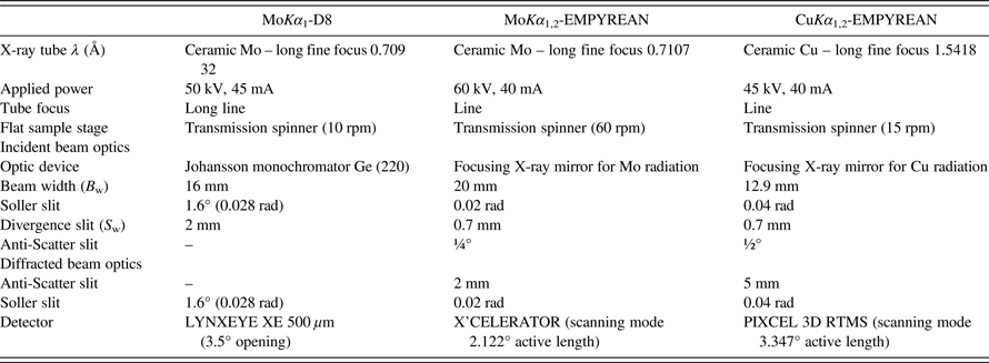
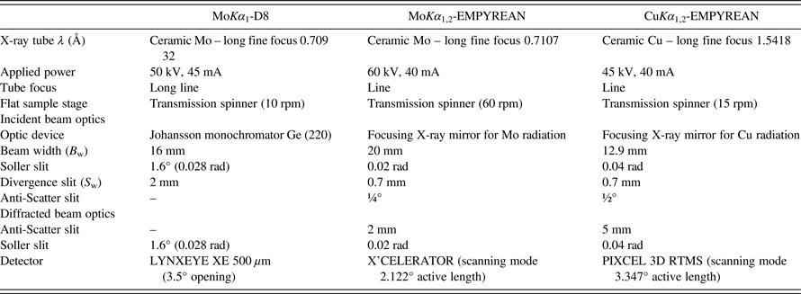
Table I gives experimental set-up details for the three diffractometers used for this type of data collection.
-
(1) D8 ADVANCE DaVinci (Bruker AXS) diffractometer (250 mm of diameter) with Mo radiation equipped with a primary Johansson monochromator Ge (220), which gives a strictly monochromatic radiation (λ = 0.7093 Å), MoKα 1. The energy-dispersive linear detector LYNXEYE XE 500 µm, specific for high energetic radiation, was used.
-
(2) EMPYREAN diffractometer (PANalytical B.V.) with a θ/θ goniometer (240 mm of diameter) with Mo radiation equipped with focusing mirror component used in the incident beam path, which is capable of converting the divergent beam into a convergent radiation focused on the goniometer circle. The focusing mirror is able to eliminate MoKβ, yielding MoKα 1,2 radiations. Raw patterns were mathematically treated to strip MoKα 2; see below. Data were collected preserving constant volume assumption (2θ scan mode). The detector used was the silicon-based position-sensitive detector, X´Celerator, it measures up to 100 times faster than with a traditional point detector, without compromising data quality.
-
(3) EMPYREAN diffractometer (PANalytical B.V.) with a θ/θ goniometer (240 mm of diameter) with Cu radiation equipped with focusing mirror, operating as described just above, yielding CuKα 1,2 radiations. The geometrical configuration of this diffractometer gives a maximum angle of measurement of 40°, which is low for Cu radiation. Consequently, constant volume assumption was not preserved during data collection (gonio scan mode). The photon counting X-ray detector, PIXCEL 3D, was used. This detector can operate in the 1D mode offering a very small strip size and extremely high dynamic range and low noise.
Table I. Transmission LXRPD experimental setups with flat samples.
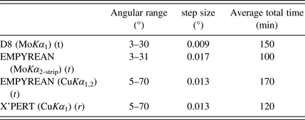
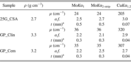
The powder samples were placed (for the three diffractometers) in the holders between two Kapton foils. Table II gives the details about data acquisition. Moreover, the absorption factors of each sample were experimentally measured by comparison of the direct beam with and without sample. The amount of sample loaded in the sample holders were controlled to obtain a total absorption (μt ~ 1), which corresponds to an absorption factor of ~2.7 or 63% of direct attenuation (Cromer and Liberman, Reference Cromer and Liberman1981). Table III gives linear absorption coefficients, fractional attenuation factor of the beam owing to absorption (experimentally measured) as well as the calculated thickness (t) using Lambert–Beer law and a supposed packing fraction of 75%.
Table II. Data acquisition details for the LXRPD patterns collected using Mo and Cu radiations in transmission (t) and reflection geometries (r).

Table III. Density (ρ), linear absorption coefficient (μ), fractional attenuation factor of the beam because of absorption (a.f.), and thickness (t) of flat samples for transmission LXRPD measurements.
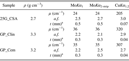
a75% packing factor is assumed.
C. Reflection CuKα 1-LXRPD data acquisition
Patterns were also recorded in Bragg–Brentano reflection geometry (θ/2θ) on an X'Pert MPD PRO (PANalytical B.V.) diffractometer (240 mm of diameter) using strictly monochromatic CuKα 1 radiation (λ = 1.540 59 Å) [Ge (111) primary monochromator]. The X-ray tube worked at 45 kV and 40 mA. The optics configuration was a fixed divergence slit (1/2°), a fixed incident anti-scatter slit (1°), a fixed diffracted anti-scatter slit (1/2°) and X'Celerator RTMS (real-time multiple strip) detector, working in the scanning mode with the maximum active length.
D. Transmission SXRPD
SXRPD patters were collected in the Debye–Scherrer (transmission) mode using the X-ray powder diffraction station of ALBA, the Spanish Synchrotron Radiation Facility (Barcelona, Spain) (Knapp et al., Reference Knapp, Peral, Nikitina, Quispe and Ferrer2011). The wavelength, 0.620 15(2) Å, was selected with a double-crystal Si (111) monochromator and determined from a Si640d NIST standard (a = 5.431 23 Å). The diffractometer is equipped with a MYTHEN detector system especially suited for time-resolved experiments. This detector system is not optimized for high-resolution experiments, nevertheless its suitability to perform RQPA has been previously checked (Alvarez-Pinazo et al., Reference Alvarez-Pinazo, Cuesta, García-Maté, Santacruz, Losilla, Sanfélix, Fauth, Aranda and De la Torre2014). The capillaries of 0.7 mm of diameter were rotated during data collection to improve diffracting particle statistics. The data acquisition time was ~25 min per pattern to attain very good signal-to-noise ratio over the angular range 1–35° (2θ). The temperature inside the experimental hutch was 299(1) K.
E. XRPD data analysis
The focusing mirror used in EMPYREAN diffractometers causes a wavelength shift of Kα 2 radiation. The effect is very small for copper wavelength, but it becomes noticeable for short wavelengths such as Mo radiation. Consequently, MoKα 2 data were stripped using the modified wide Rachinger (Reference Rachinger1948) algorithm of Delhez and Mittemeijer (Reference Delhez and Mittemeijer1975) as implemented in HighScore+ (v. 3.0e) PANalytical software, using Kα 2 shift value of 0.005, Kα 2/Kα 1 intensity ratio of 0.6 and a wavelength ratio correction of 0 ppm.
In order to obtain RQPA, all patterns were analyzed using the Rietveld methodology as implemented in the GSAS software package (Larson and Von Dreele, Reference Larson and Von Dreele2004). Crystal structure descriptions used for all the phases were those reported in Aranda et al. (Reference Aranda, De la Torre and León-Reina2012). Final global optimized parameters were: background coefficients, zero-shift error, cell parameters, peak shape parameters and March–Dollase (Dollase, Reference Dollase1986) preferred orientation parameter, when appropriated. Peak shapes were fitted using the pseudo-Voigt function (Thompson et al., Reference Thompson, Cox and Hasting1987) with the asymmetry correction of Finger et al. (Reference Finger, Cox and Jephcoat1994) included.
III. RESULTS AND DISCUSSIONS
A. Characterization of peak widths
The instrumental contribution to peak broadening for LXRPD and SXRPD was determined with Standard Reference Material (SRM) LaB6 and Na2Ca3Al2F14 (NAC) standards, respectively. Figure 1 shows measured full-width at the half-maximum (FWHM) as a function of angle for all the diffractometers and configurations used in this study.

Figure 1. FWHM evolution with diffracting angle for all diffractometers and configurations used in this study.
The SXRPD pattern yielded the narrowest diffraction peaks. FWHM values were ≈0.02° (2θ), and not the smallest possible values ≈0.006°, as the configuration used was the MITHEN detector and not the crystal analyzer detector system. On the other hand, the broadest diffraction peaks arisen from the CuKα 1,2 transmission geometry with the focusing mirror although the values ranged 0.08°–0.10° (2θ) are small enough to be considered medium-resolution data.
The most important outcome from this analysis is the observation of quite low FWHM values for strictly monochromatic MoKα 1 radiation. As depictured in Figure 1, FWHM values ranged 0.03°–0.05° (2θ). These low values imply that peak overlapping is not much important than in CuKα 1 powder diffraction data.
B. Comparison of irradiated volumes
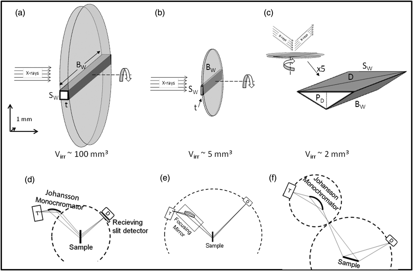
Any analytical technique requires a representative sample or sampling. Irradiated volume in diffraction is a key issue since higher volume yields enhanced particle statistics. Therefore, the use of a high-energy radiation is beneficial as the irradiated volume of sample can be increased, and absorption effects can be reduced. Figure 2 shows a graphical representation of the volumes that are bathed by X-ray radiations for the laboratory diffraction geometries (transmission and reflection, also included in Figure 2) used in this study.

Figure 2. Irradiated volume for flat sample holder in the transmission mode using (a) molybdenum radiation and (b) copper radiation; and (c) reflection mode using copper radiation. Diffraction geometry sketches (d) transmission geometry with primary monochromator, (e) transmission geometry with focusing mirror, and (f) reflection geometry with primary monochromator.
Figures 2(a) and 2(b) give the irradiated volumes bathed by X-rays when using flat samples, which are spun about the normal to the sample surface during data acquisition (shadowed zone) for Mo and Cu radiations, respectively. The total irradiated volume is calculated as V = π(B w/2)2 t, where B w stands for the beam width (see Table I) and it is defined by optical components on the incident beam. On the other hand, t is the thickness of the sample. These values are calculated using Lambert–Beer law: t = −[ln(1/a.f.)]/μρc, being a.f. the experimentally determined absorption factor, μ the mass absorption coefficient in cm2 g−1, ρ the density in g cm−3, and c the packing fraction, assumed to be 75% in these calculations; see Table III. Taking into account these data, the irradiated volume for Mo-radiation is close to 100 mm3, whereas for Cu-radiation the value is not larger than 5 mm3. Unfortunately, the latter cannot be enlarged without decreasing the resolution and having strong absorption effects.
Finally, Figure 2(c) gives the irradiated volume for reflection geometry with Cu-radiation. In this case, the beam and slit widths are also defined by the incident beam optic components (Table I) and penetration depth (P D) has been calculated assuming an attenuation factor of 63% (equivalent to an absorption factor of 2.7) at an incident angle of 40°. Sample holder is also spun about the normal to the sample surface during data collection [shadowed zone in Figure 2(c)], consequently the irradiated volume is close to 2 mm3 calculated as a truncated cone, V = 1/3πP D[(D/2)2 + (B W/2)2 + (D/2) (B W/2)] and D = (B W 2 + SW 2)1/2. Furthermore, the enlargement of this value is not possible as it only depends on the absorption factor of the sample.
C. Constant volume assumption
As detailed in the experimental section, patterns obtained in transmission geometry with Cu radiation did not preserved the constant volume assumption. The intensity of the pattern was increased by a factor of 1/cosθ as a consequence of an increase in the irradiated volume during data collection (Klug and Alexander, Reference Klug and Alexander1974). On the other hand, the intensity was reduced as a consequence of higher absorption by a factor of e µt[1−(1/cosθ)], where μ stands for the mass absorption coefficient and t for the calculated thickness of the sample, both parameters given in Table III (Klug and Alexander, Reference Klug and Alexander1974). Consequently, the collected intensity should be corrected by a factor of 1/cosθ × e µt[1−(1/cosθ)].
This correction was applied to 25G_CSA and GP_Clin patterns in order to check the effect of not preserving the constant volume assumption on RQPA. Figure 3 shows the raw pattern of 25G_CSA (in red) and corrected data using the correction factors given in the inset of Figure 3. An enlarged range of the high-angle region of the patterns has been included as an inset to show that both patterns are almost coincident. Moreover, RQPA obtained by analyzing both raw and corrected data are included in Tables IV and V, in the CuKα 1,2 column. It can be observed that the results are almost the same. Consequently, in the collected angle range of this study the effect of not preserving the constant volume assumption is not significantly affecting RPQA and this correction was not applied to remaining patterns collected in transmission geometry with Cu radiation.

Figure 3. Raw (red) and corrected (black) data for 25G_CSA. Inset shows the applied correction factors considering the improvement of irradiated volume and absorption.
Table IV. Comparative of the RQPAs for sample 25G_CSA measured with different radiations (Mo, Cu, and synchrotron) and geometries [reflection (r) and transmission (t)].

aRQPA obtained after the application of the correction factor because of not preserving the constant volume assumption.
Table V. Comparative of the RQPAs for sample GP_Clin measured with synchrotron, Mo, and Cu radiations, as in Table IV.

aMean and standard deviation values from the Round Robin study (León-Reina et al., Reference León-Reina, De la Torre, Porras-Vázquez, Cruz, Ordonez, Alcobé, Gispert-Guirado, Larrañaga-Varga, Paul, Fuellmann, Schmidt and Aranda2009). In this case, the average values and the standard deviations were derived from the results of the 14 participants.
bRQPA obtained after the application of the correction factor because of not preserving the constant volume assumption.
D. Accuracy study
One of the main objectives of this work is to evaluate the accuracy of RQPA obtained from MoKα-LXRPD data. A comparison of the technical performances of the detectors used here are out of the scope of the present study. As discussed in the Introduction section, cement samples are used as a benchmark owing to their complexity. So, a CSA clinker was mixed with 25 wt% of crystalline gypsum [CaSO4·2H2O or CSH2, in cement nomenclature (cement nomenclature: C = CaO, S = SiO2, A = Al2O3, F = Fe2O3, S = SO3, M = MgO, and T = TiO2)], labeled as 25G_CSA. The accuracy of the quantitative analysis of gypsum in this sample was confirmed by comparison to the weighed value and also to the value obtained from an alternative technique differential thermal analysis (DTA) and thermo-gravimetric analysis (TGA) (Rajczyk and Nocun-Wczelik, Reference Rajczyk and Nocun-Wczelik1992). Hence, the sample was heated from RT to 1273 K at a rate of 10° min−1, and its mass variation was accurately monitored. Gypsum has its own characteristic temperature range of dehydration. By the specific mass loss at ~360 K, which corresponds to the release of two water molecules, it could be inferred the gypsum amount which was 24.96 wt%; see Table IV.
Table IV also gives RQPA for 25G_CSA obtained by analyzing the data collected using different diffraction geometries and radiations. Strictly monochromatic Cu radiation has been used in reflection geometry (CuKα 1), whereas CuKα 1,2 radiations were used in transmission with flat sample (CuKα 1,2 data in Table IV). Molybdenum radiation has only been used in the transmission mode with flat sample with two different optic components: (i) a primary monochromator, labeled as MoKα 1 in Table IV and (ii) a focusing mirror, labeled as MoKα 2-strip in Table IV. Moreover, SXRPD data (labeled as synchr. λ = 0.62 Å in Table IV) have been collected in the transmission mode with the samples loaded in a capillary as described in the experimental section.
It is worthwhile to underline that the well-known weighed sample used, gypsum, is a layered compound and therefore, it usually displays preferred orientation effect. In any case, we have used this phase as it is ubiquitously used in the cement field as set regulator. Furthermore, if the analyses yield good values for this extreme case, in more favorable situations the outcome could be even better. As shown in Table IV, the March–Dollase preferred orientation coefficient, along the [0 1 0]-axis, behaved as expected. The refined value for a flat sample in reflection geometry was smaller than 1, i.e. 0.73. The refined values for flat samples in transmission geometry were larger than 1 ranging between 1.09 and 1.30. Finally, the SXRPD pattern collected in the transmission, but in a capillary did not showed the preferred orientation for gypsum and so this effect was not corrected in this analysis.
High-resolution SXRPD minimizes most of the experimental artifacts that may cause errors in the patterns. The value for gypsum content obtained by SXRPD was 26.1 wt%, which compares very well with the added value 25.0 wt%; see Table IV. The error is 1.1 wt% (absolute value) or 4.6% (relative value). Furthermore, this small discrepancy can be explained by the presence of a small amount of amorphous phase in the CSA clinker, which would result in a small overestimation of the RQPA result for the added gypsum. The values obtained from MoKα radiation are close to 27 wt% (see Table IV), about 2 wt% (absolute error) or 10.5 and 7.4% relative errors for MoKα 1 and MoKα 2-strip analyses, respectively. Finally, the larger error (lower accuracy) is obtained from Cu-radiation patterns. The RQPA-derived gypsum contents were 28.7 and 31.0 wt% for CuKα 1,2 and Cu Kα 1 patterns, respectively. In this case, the relative errors were as large as 14.8 and 24% (relative values). As expected, for LXRPD data, accuracy in the RQPA results improves as the irradiated volume increases.
E. Accuracy study from an inter-laboratory comparison
The assessment of the accuracy of RQPA results from Mo-radiation was also performed by analyzing two commercial samples, previously used in a Round Robin of building materials (León-Reina et al., Reference León-Reina, De la Torre, Porras-Vázquez, Cruz, Ordonez, Alcobé, Gispert-Guirado, Larrañaga-Varga, Paul, Fuellmann, Schmidt and Aranda2009). Tables V and VI give RQPA of GP_Clin and GP_Cem, respectively. The first column in these tables gives the mean values and standard deviations obtained in that study (in bold) and they are considered as “true values” and they were derived from the reported values by the 14 experienced participants. The RQPA results obtained by the radiations and geometries described in the experimental section are also given in these tables. The standard deviation reported in Tables V and VI, for the RQPA obtained in this study, are mathematically derived errors. For the sake of comparison Figure 4 gives Rietveld plots for GP_Cem collected with LXRPD with Mo and Cu radiations in transmission.

Figure 4. Rietveld plots for GP_Cem collected in the transmission mode with flat sample with (a) strictly monochromatic MoKα 1 radiation, (b) MoKα 2-striped radiation, and (c) CuKα 1,2 radiations.
Table VI. Comparative of the RQPAs for sample GP_Cem measured with Cu, Mo, and synchrotron radiations, as in Table IV.
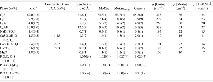
aMean and standard deviation values from the Round Robin study (León-Reina et al., Reference León-Reina, De la Torre, Porras-Vázquez, Cruz, Ordonez, Alcobé, Gispert-Guirado, Larrañaga-Varga, Paul, Fuellmann, Schmidt and Aranda2009). In this case, the average values and the standard deviations were derived from the results of the 14 participants.
As expected, RQPA results for the SXRPD data showed the closest agreement with the reported values in the Round Robin study. In fact, the RQPA results agree within one standard deviation for most of the phases. Then, the next closest agreement is the Mo-radiation patterns with quite good agreement; see Tables V and VI. For GP_Clin sample RQPA results from MoKα 1 radiation are almost identical to those obtained from synchrotron radiation. As the sample complexity increases, GP_Cem (Table VI), the deviations are a bit larger but still the values are quite similar.
Finally, the deviation dramatically increased in RQPA results obtained from transmission geometry with CuKα 1,2 radiation. It is well known that main C3S and C2S peaks are severely overlapped and the use of polychromatic radiation has likely increased the correlations in data analysis. Transmission CuKα 1,2 Rietveld results for both samples followed the general trend obtained in previous studies (De la Torre and Aranda, Reference De la Torre and Aranda2003; León-Reina et al., Reference León-Reina, De la Torre, Porras-Vázquez, Cruz, Ordonez, Alcobé, Gispert-Guirado, Larrañaga-Varga, Paul, Fuellmann, Schmidt and Aranda2009), showing an underestimation of C3S and an overestimation of C2S respect to mean values, although the total silicate content is almost constant.
The obtained values by DTA–TGA are also included in Table VI, as an alternative way to evaluate the accuracy of the obtained results. The percentages of gypsum obtained by both methods (RQPA and thermal analysis) are very similar. However, the percentages of bassanite obtained with synchrotron and Mo radiations resulted in underestimated values when compared to the DTA–TGA value. These differences could be because of the poor crystallinity of this phase, which may result in a smaller content for the crystalline fraction. On the other hand, the calcite amount obtained by RQPA is slightly overestimated in the patterns collected in this study, likely because of the strong overlapping between C3S and calcite main peaks, which makes problematic the calcite quantification at low contents.
F. RQPA of very complex systems
Three hydrated cements have been analyzed using strictly monochromatic MoKα 1 radiation. RQPA results were cross-checked by comparison to the results from SXRPD data for the same samples. In addition to some remaining phases from the anhydrous cements, three hydrated crystalline phases are expected in these types of pastes: ettringite, stratlingite, and katoite (Alvarez-Pinazo et al., Reference Alvarez-Pinazo, Santacruz, León-Reina, Aranda and De la Torre2013, Reference Alvarez-Pinazo, Cuesta, García-Maté, Santacruz, Losilla, Sanfélix, Fauth, Aranda and De la Torre2014). Some amounts of calcium carbonate (calcite and vaterite) were also quantified. These carbonates likely arise from the carbonation of portlandite, Ca(OH)2, which is one of the hydration products of dicalcium silicate, a.k.a. belite. The complexity of these systems is clear from Table VII as eight crystalline phases are present. Figure 5 gives Rietveld plots for G10B0 sample (MoKα 1 and synchrotron patterns) as a representative example. Figure 5 highlights not only the complexity of the sample (with eight crystalline phases), but also the high-resolution features of the MoKα 1 pattern, where the diffraction peak overlapping is very similar to that observed in the synchrotron pattern.

Figure 5. Rietveld plots for G10B0 hydrated sample patterns (a) strictly monochromatic MoKα 1 radiation in transmission with the flat sample, (b) synchrotron radiation in transmission with the sample in a capillary.
Table VII. Comparative of the RQPA results (wt%) for the hydrated samples measured with MoKα 1 and synchrotron radiations.

aPhase from the anhydrous cement.
bPhase resulting from the hydration reactions.
Two main conclusions can be derived from the RQPA results reported in Table VII. Firstly, the carbonation effects are clearly observed in these patterns with the calcium carbonate (calcite and vaterite phases) slightly evolving with time. Secondly, in spite of the carbonation effects and the complexity of the systems, the derived contents for the main crystalline phases agree relatively well in both studies.
IV. CONCLUSION
Irradiated volume in diffraction is a key issue since higher volume yields enhanced particle statistics. Therefore, the use of a high-energy radiation is beneficial as the irradiated volume of the sample can be increased. Moreover, quite low FWHM values for strictly monochromatic MoKα 1 diffraction peaks have been measured. Low FWHM values indicate that peak overlapping is not much more important than in CuKα 1 powder diffraction. So, the optimum results for strictly monochromatic Mo radiation arise from the large tested volumes meanwhile peak overlapping is not enlarged.
ACKNOWLEDGEMENTS
This work has been supported by Junta de Andalucía through P11-FQM-7517 research grant and by Spanish MINECO through MAT2010-16213 research grant, which is co-funded by FEDER. I. Santacruz acknowledges a Ramón y Cajal fellowship, RYC-2008-03523. PANalytical B.V. (Almelo, The Netherland) and Bruker (Karlsruhe, Germany) are thanked by providing the Mo-radiation diffractometers. ALBA is thanked for providing synchrotron beamtime at BL04-MSPD beamline.


