I. INTRODUCTION
Extraordinary properties of graphene make it attractive for applications in polymer-based composite materials (Stankovich et al., Reference Stankovich, Dikin, Dommett, Kohlhaas, Zimney, Stach, Piner, Nguyen and Ruoff2006; Xu et al., Reference Xu, Wang, Liang, Huang, Ma, Wan and Chen2009; Pramoda et al., Reference Pramoda, Hussain, Koh, Tan and He2010; Tung et al., Reference Tung, Kim, Shim, Yang, Kim and Suh2011). Several methods have been developed to prepare graphene, such as mechanical exfoliation method, chemical vapor deposition method, epitaxial growth on silicon carbide, and oxidation–reduction of graphite method. It has been verified that an exciting method for low-cost and large-scale production of graphene is by reducing the precursor of graphene oxide to obtain reduced graphene oxide (RGO) (Fernandez-Merino et al., Reference Fernandez-Merino, Guardia, Paredes, Villar-Rodil, Solis-Fernandez, Martinez-Alonso and Tascon2010; Zhu et al., Reference Zhu, Guo, Fang and Dong2010). However, the loss of oxygen-containing groups on the basic plane of graphene by chemical reduction leads to the poor dispersibility in various solvents. The higher the reduction degree, the more serious the aggregation is. Thus, the re-aggregation of RGO sheets is undesirable for many applications in graphene-based composites. To overcome these problems, covalent and non-covalent functionalizations of RGO platelets have been performed (Stankovich et al., Reference Stankovich, Dikin, Dommett, Kohlhaas, Zimney, Stach, Piner, Nguyen and Ruoff2006; Wang et al., Reference Wang, Shen, Wang, Yao and Park2009, Reference Wang, Liu, Sun, Stach, Zhang, Stanciu and Xie2012; Chang et al., Reference Chang, Wang, Yang, Tao, Liu, Shen and Zheng2010; Pramoda et al., Reference Pramoda, Hussain, Koh, Tan and He2010; Kuila et al., Reference Kuila, Bose, Khanra, Kim and Lee2011; Zhang et al., Reference Zhang, Mao, Zhang, Chan, Zhao and Wu2011; Fan et al., Reference Fan, Liu, Cai, Liu and Zhang2012; Yang et al., Reference Yang, He, Peng, Baji, Du, Huang, Xie and Mai2012; Uddin et al., Reference Uddin, Kuila, Nayak, Kim, Ku and Lee2013).
Surfactants have been used in modified carbon nanomaterials, such as carbon nanotube (Goh et al., Reference Goh, Ng, Ismail, Aziz and Sanip2010) and graphene (Wang et al., Reference Wang, Shen, Wang, Yao and Park2009; Chang et al., Reference Chang, Wang, Yang, Tao, Liu, Shen and Zheng2010; Pramoda et al., Reference Pramoda, Hussain, Koh, Tan and He2010; Kuila et al., Reference Kuila, Bose, Khanra, Kim and Lee2011; Zhang et al., Reference Zhang, Mao, Zhang, Chan, Zhao and Wu2011; Fan et al., Reference Fan, Liu, Cai, Liu and Zhang2012; Uddin et al., Reference Uddin, Kuila, Nayak, Kim, Ku and Lee2013), in order to prepare a well-dispersed suspension. The presence of amphiphilic surfactant molecules on the graphene surface can effectively inhibit the re-aggregation of non-polar graphene sheets, but usually results in a weak conductive graphene. Uddin et al. (Reference Uddin, Kuila, Nayak, Kim, Ku and Lee2013) reported that sodium dodecyl benzene sulfonate (SDBS), sodium dodecyl sulfate (SDS), and 4-(1,1,3,3-tetramethylbutyl) phenyl-polyethylene glycol (Triton X-100)-modified graphene all showed a conductivity of approximately 100 S m−1, which is far lower than non-functionalized graphene (4760 S m−1) under the same condition. Fan et al. (Reference Fan, Liu, Cai, Liu and Zhang2012) prepared cetyltrimethylammonium bromide-(CTAB)-modified graphene with a conductivity of 3719 S m−1, which is still a little lower than that of RGO without modification (Fernandez-Merino et al., Reference Fernandez-Merino, Guardia, Paredes, Villar-Rodil, Solis-Fernandez, Martinez-Alonso and Tascon2010). Therefore, it must be considered how to remove the residual surfactant molecules in order to obtain highly conductive graphene without compromising a homogeneous dispersion of RGO sheets.
In this work, we took advantage of amphiphilic property of a thermal-unstable, inexpensive, and water-soluble cetyltrimethylammonium chloride (CTAC) to modify the RGO surface during the hydrazine reduction process. Then a thermal annealing process in H2/Ar was used to remove the non-conductive CTAC and further reduce RGO sheets. The resulting RGO showed a high conductivity. Moreover, the aggregation of graphene was effectively inhibited. The electrical conductivity of RGO annealing at 500 °C reached up to 2.23 × 10⁴ S m−1, which was about 400 times as large as that of CTAC-modified RGO. The effect of annealing temperature on RGO conductivity is discussed. With the high-conductive RGOs, the prepared 5 wt% graphene/polymethylmethacrylate (PMMA) nanocomposites also exhibited a conductivity of 4.11 S m−1, which showed nearly 14 orders of magnitude higher conductivity than pure PMMA. It was also far higher than the conductivity of directly reduced RGO/PMMA composite without addition of surfactant with the same filler content. Our work may provide guidance for manufacturing highly conductive and non-aggregated graphene and its polymer-based nanocomposites.
II. EXPERIMENTAL DETAILS
A. Materials
Natural flake graphite (NFG) (325 mesh) was purchased from Alfa Aesar. N,N-dimethylformamide (DMF), nitric acid, sulfuric acid (H2SO4; 96%), and hydrogen peroxide (H2O2; 30%) were obtained from Beijing Chemical Works (Beijing, China). Anhydrous methanol, potassium permanganate (KMnO4), sodium nitrate (NaNO3), and CTAC were provided by Sinopharm Chemical Reagent Co., Ltd. PMMA polymer (Mw = 413 500 g mol−1) was purchased from Tokyo Chemical Industry Co., Ltd. All chemicals were analytical grade and used as received.
B. Preparation of CTAC-modified RGO and removal of CTAC
Graphite oxide (GO) was prepared by the modified Hummer's method according to our previous work (Zeng et al., Reference Zeng, Yang and Yuan2012). GO products were then subjected to a two-step process – (i) modified with CTAC and reduced by hydrazine hydrate and (ii) annealed in H2/Ar (mass ratio 1:1) for 2 h at the temperature range of 200–700 °C.
First, the dried GO (200 mg) was placed in a beaker and then 40 ml of distilled water were added. The mixture was sonicated (240 W) for 2 h to obtain a graphene oxide suspension. Then 200 mg of CTAC were added into the graphene oxide suspension and the mixture was stirred for 24 h at room temperature. After that, hydrazine monohydrate (60 μl per 12 mg of GO) was subsequently added into the suspension, which was then placed in an 80 °C water bath for 2 h with continuous stirring. The obtained black product was filtered and washed with distilled water, and finally dried in a vacuum oven at 60 °C for 12 h to obtain a fluffy powder, which was designated as C-RGO. For comparison, the product without addition of CTAC in the same process was designated as N-RGO.
Secondly, the as-prepared C-RGO was heated for 2 h in a tube furnace (heating rate 8 °C min−1) under a mixture of hydrogen and argon. The flow was controlled by a mass flow controller and the ratio of H2/Ar was 1:1. The samples of C-RGO annealed at 200, 300, 400, 500, and 700 °C were marked as C-RGO-200, C-RGO-300, C-RGO-400, C-RGO-500, and C-RGO-700, respectively.
C. Preparation of RGO/PMMA nanocomposites
The C-RGO-500/PMMA (C-RGO/PMMA or N-RGO/PMMA) nanocomposites were prepared by a solution-based intercalation method. At first, 80 mg C-RGO-500 (C-RGO or N-RGO) was dissolved in 80 ml of DMF and then was sonicated (240 W) for 2 h. 40 ml of PMMA/DMF solution (40 g l−1) were added with stirring (200 rpm) and sonication (240 W), which continued for 2 h to obtain a well-dispersed C-RGO-500/PMMA (C-RGO/PMMA or N-RGO/PMMA) nanocomposites. The crude product was then poured into a beaker filled with methanol under vigorous stirring (300 rpm). The precipitate was filtered through a nylon membrane filter (1.2 μm pore size), and washed with methanol for three times. The product was dried in a vacuum at 80 °C for 12 h.
The whole process for preparing C-RGO-500 and C-RGO-500/PMMA nanocomposites is illustrated in Figure 1.

Figure 1. Schematic illustration of preparation of C-RGO-500/PMMA composites.
D. Characterizations
The crystal phases of NFG, CTAC, GO, C-RGO, RGO, C-RGO-500, and N-RGO were characterized by powder X-ray diffraction (XRD) on a Philips X'Pert Pro X-ray polycrystalline diffractometer with CuKα radiation. The Fourier-transformed infrared (FTIR) spectra of the samples were recorded by a Nicolet6700 FTIR spectrometer. Atomic force microscopy (AFM; Veeco, Dimension V) was employed to measure the thickness of graphene sheets. The X-ray photoelectron spectra (XPS) of GO, N-RGO, C-RGO, and C-RGO-500 were obtained with a PHI Quantera XPS equipment. Transmission electron microscopy (TEM) was performed on a F20 S-TWIN electron microscope (Tecnai G2, FEI Co.), using a 200 kV accelerating voltage. The surface morphology of the samples was observed by a field emission scanning electron microscopy (FESEM) system (S-4800, Hitachi, Japan). The Brunauer–Emmett–Teller (BET)-specific surface area of the C-RGO, C-RGO-300, C-RGO-500, and C-RGO-700 was measured by nitrogen adsorption at 77 K on a Quantachrome Instrument Version 2.0.
When the conductivity of the sample was higher than 10−4 S m−1, the electrical properties were measured using an HL 55WIN Hall System by Vander Paw method. For low conductive samples (<10−4 S m−1), the measurement was performed on an Agilent 4294A impedance analyzer system. Before measurement, the prepared C-RGO-500/PMMA (N-RGO/PMMA or C-RGO/PMMA) particles were ground into powder using an agate mortar, and then were pressed into thin pieces using a tablet press under a pressure of 20 MPa.
III. RESULTS AND DISSCUSSION
It has been found that graphene sheets in the presence of surfactant molecules can show a decrease in conductivity of graphene owing to the surfactant non-conductive properties (Fan et al., Reference Fan, Liu, Cai, Liu and Zhang2012; Uddin et al., Reference Uddin, Kuila, Nayak, Kim, Ku and Lee2013). How to eliminate the non-conductive CTAC from C-RGO sheets is an important consideration. CTAC surfactant is unstable when heating, and it decomposes into alkenes and organic ammonium salt above 200 °C. As H2 can be used as a reduction gas, thermal annealing of C-RGO in H2 may be a better choice. Hence, the CTAC molecules can be removed in H2/Ar with heating.
Figure 2 shows the conductivity and weight loss of C-RGO annealed at different temperatures in H2/Ar. The conductivity of C-RGO is measured as 55.5 S m−1. This value is markedly lower than that of RGO with the same C/O ratio (Pei et al., Reference Pei, Zhao, Du, Ren and Cheng2010), and far lower than N-RGO (8.98 × 10³ S m−1, this work) with the same reduction process without addition of CTAC. After additional annealing under H2/Ar atmosphere, the conductivity of C-RGO increases significantly. The increase of conductivity can be attributed to two aspects. On the one hand, the content of non-conductive CTAC molecules in the C-RGO decreases with the increase of temperature, because CTAC is unstable under high temperature in H2/Ar. The weight decrease of C-RGO can be seen from the weight loss curve of C-RGO in Figure 2. In particular, before 400 °C the weight loss of C-RGO is evident. In addition, with the increase of temperature the reduction degree of C-RGO can also be augmented, which can be verified from the XPS spectrum and XRD patterns. As the conductivity of C-RGO-400 (9.10 × 10³ S m−1) approximates to that of N-RGO, we suppose the increase of the conductivity of RGO before 400 °C is principally due to the removal of CTAC. And after 400 °C, further reduction of C-RGO is the main reason for the increasing of conductivity.

Figure 2. Curve of weight loss and conductivities of the samples of C-RGO after annealing at different temperatures in H2/Ar atmosphere. The inset table shows a comparison of the specific surface area of the samples.
As the continuous removing of CTAC and enhancement in reduction degree of C-RGO, the conductivity of C-RGO-500 reaches 2.23 × 10⁴ S m−1, which is 400 times larger than that of C-RGO and six times higher than that of CTAB-modified RGO (Fan et al., Reference Fan, Liu, Cai, Liu and Zhang2012). Although the conductivity of C-RGO-700 is a bit higher than C-RGO-500, the specific surface area of C-RGO-700 is much lower than C-RGO-500 (see the inset table of Figure 2). The reason might come from the increase of particle sizes. As the high specific surface area of graphene is beneficial for graphene/polymer composites (Stankovich et al., Reference Stankovich, Dikin, Dommett, Kohlhaas, Zimney, Stach, Piner, Nguyen and Ruoff2006), it is not suitable to dispose C-RGO when the temperature is too high. This feature is different from thermal exfoliation of graphene (Zhang et al., Reference Zhang, Zheng, Yan, Jiang and Yu2012). In our work, C-RGO-500 is chosen as the optimal filler for preparing graphene/PMMA nanocomposites.
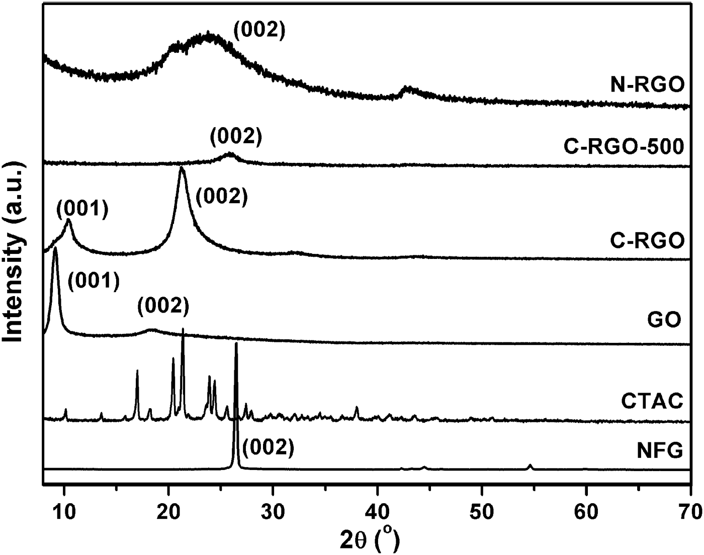
The powder XRD patterns of the raw materials and prepared products are shown in Figure 3. The characteristic peak (002) of the NFG (PDF card: 41-1487, Campbell et al., Reference Campbell, Kelly and Peacock1989) is detected at 2θ = 26.5°. After oxidation, a strong peak at 2θ = 9.1° related to the characteristic peak (001) of GO is observed (Zhang et al., Reference Zhang, Mao, Zhang, Chan, Zhao and Wu2011), indicating that the NFG is effectively oxidized. After CTAC is added and then reduced by hydrazine hydrate, a peak appears at 21.2° for C-RGO, which is because of a random stack of RGO sheets. It is noted that a weaker peak of C-RGO at 10.4° emerges, which is owing to the insufficient reduction of GO. With further reduction under H2/Ar flow at the temperature of 500 °C, the characteristic peak (001) of GO disappears, and there only exists a wide peak (002) at 26.3°. This corresponds to the characteristic peak of stacked graphene layers, showing that the additional exposure with hydrogen and argon can effectively eliminate the residual oxygen functional groups on the graphene plane. Although the mass of added CTAC was the same as that of GO, there is no obvious characteristic peak of CTAC in C-RGO. This result is in accordance with the work reported by Zhang et al. (Reference Zhang, Mao, Zhang, Chan, Zhao and Wu2011). Moreover, the difference in the XRD patterns between C-RGO and N-RGO also indicates the CTAC has effectively interacted with RGO. Compared with C-RGO-500, the sample of N-RGO exhibits the similar XRD patterns, but the (002) peak moves to lower angle. The interlayer spacing of C-RGO (0.420 nm), N-RGO (0.375 nm), and C-RGO-500 (0.346 nm) decreases gradually. This indicates the elimination of the oxygen functional groups at the graphene plane. In other words, the reduction degree of RGO enhances. This conclusion is identical with the trend of conductivity.

Figure 3. Powder XRD patterns of NFG, CTAC, GO, C-RGO, C-RGO-500, and N-RGO samples.
Figure 4 shows the FTIR spectra of GO, CTAC, C-RGO, and C-RGO-500 samples. The peaks at 1480, 2842, and 2920 cm−1 are all observed in the spectrum of CTAC and C-RGO. The absorbance bands at 2842 and 2920 cm−1 are ascribed to C–H stretching vibration of alkyl chain of CTAC molecule (Fan et al., Reference Fan, Liu, Cai, Liu and Zhang2012). The band at 1480 cm−1 corresponds to the C–H bending (Lian et al., Reference Lian, Li, Liu, Xu, Wang and Guo2011). The results further confirm the interaction between graphene and CTAC. The above three bands are absent in the spectrum of C-RGO-500 meaning that CTAC is successfully removed after annealing at 500 °C in H2/Ar. Moreover, there are few peaks in C-RGO-500 at 3340 and 1700 cm−1, which indicates that the oxygen functional groups almost disappear. The results are consistent with the XPS data of C-RGO-500.
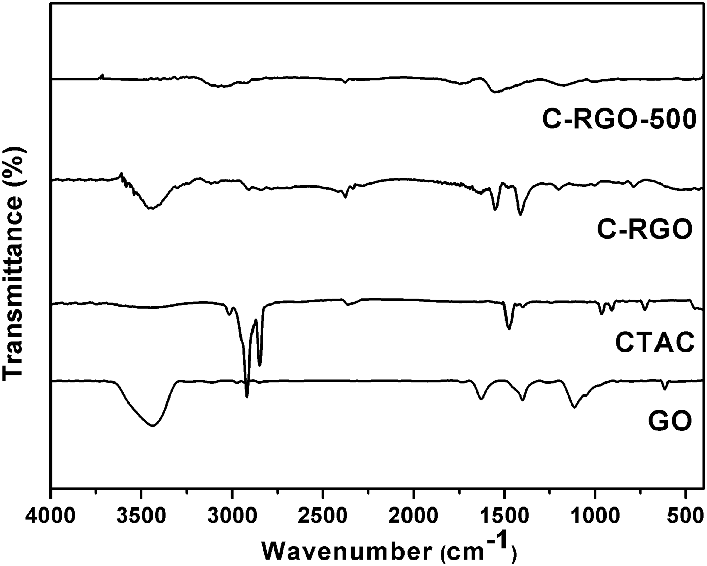
Figure 4. FTIR spectra of GO, CTAC, C-RGO, and C-RGO-500 samples.
To identify the functional groups in graphene sheets, XPS measurement was performed. Figure 5 shows C1 s XPS spectra of GO, N-RGO, C-RGO, and C-RGO-500. GO generally consists of two main components arising from C = C/C–C, as well as C–O (epoxy and hydroxyl) groups. A few of carbonyl and carboxyl groups also exist on the edge of the GO plane (Zhao et al., Reference Zhao, Pei, Ren, Gao and Cheng2010). C1s XPS spectra of N-RGO are similar to C-RGO, which means the CTAC will not obviously inhibit the reduction capacity of hydrazine hydrate. Indeed, the C/O atomic ratios of C-RGO (13.9) is a bit higher than N-RGO (12.0). The higher value of C/O is more likely attributable to the presence of CTAC on C-RGO, because CTAC has a long alkyl chain. Figures 5(b) and 5(c) indicate that after reduction of graphene oxide with hydrazine hydrate, there are only one strong peak (C = C/C–C) and three minor peaks in the C1s XPS spectrum of C-RGO and N-RGO. Compared to GO, a new peak of C–N appears at 285.7 eV, and the content of C = O and C–O decrease significantly. The remaining C = O and C–O bands demonstrate that reduction is not complete. For C-RGO, the peak of C–N comes from the addition of CTAC and the interaction between C = O and hydrazine. But the C–N peak of N-RGO only derives from the latter. In the case of C-RGO, after additional reduction by H2/Ar at 500 °C, the C = O peak disappears and the content of C = C/C–C increases (see Figure 5(d)). The C/O atomic ratios according to the XPS results are 2.1 for GO, 13.9 for C-RGO, and 31.7 for C-RGO-500, respectively. The C/O ratio of C-RGO-500 is much higher than that of RGO reduced by hydrogen iodide (Pei et al., Reference Pei, Zhao, Du, Ren and Cheng2010) or thermally shocked in hydrogen and argon at 1000 °C (Yang et al., Reference Yang, Velamakanni, Bozoklu, Park, Stoller, Piner, Stankovich, Jung, Field and Ventrice2009). The high C/O ratio of C-RGO-500 contributes to a higher conductivity compared with that of RGO (Pei et al., Reference Pei, Zhao, Du, Ren and Cheng2010) and N-RGO.

Figure 5. C1s XPS spectra of GO (a), N-RGO (b), C-RGO (c), and C-RGO-500 (d).
The AFM images and TEM measurements all manifest that the prepared C-RGO-500 consists of single- and multi-layer graphene sheets in micron size. As can be seen in Figure 6, the height of the C-RGO sheets is about 1.343 nm, which is a little higher than the height of C-RGO-500 sheets (about 1.035 nm). The increased height of C-RGO can be attributed to the residual CTAC molecules on the C-RGO sheets and the additional oxygen groups. A typical TEM image (Figure 7) also shows a curved thin flaky appearance of the prepared C-RGO-500, the results are similar to previously report data (Zhang et al., Reference Zhang, Mao, Zhang, Chan, Zhao and Wu2011).

Figure 6. AFM images for C-RGO sheets (a) 3 × 3 μm, (b) the corresponding height map in (a), and C-RGO-500 sheets (c) 3 × 3 μm, and (d) the corresponding height map in (c).

Figure 7. TEM images of C-RGO-500 under (a) low magnification and (b) high magnification (high-resolution TEM).
The morphologies of C-RGO and C-RGO-500 characterized by FESEM are shown in Figures 8(a) and 8(b). The samples all exhibit a typical wrinkled morphology of graphene, similar to CTAB intercalated RGO, but far different from the agglomerated graphite-like particles (Zhang et al., Reference Zhang, Mao, Zhang, Chan, Zhao and Wu2011). The similar morphology of C-RGO and C-RGO-500 indicates that the fluffy structure of RGO is dominated by the role of CTAC. Additional annealing in H2/Ar cannot visibly influence the structure of graphene. This crumpled surface morphology of C-RGO-500 might be beneficial for fabricating graphene-based polymer composites. Composites of C-RGO-500/PMMA were prepared to evaluate the role of C-RGO-500 in a PMMA matrix. The FESEM images of C-RGO-500/PMMA nanocomposites, seen in Figures 8(c) and 8(d), are similar to the previous report (Wang et al., Reference Wang, Hu, Wang, Xu, Zhang and Shang2011). The PMMA microspheres are immobilized on or anchored to the surface of C-RGO-500. The interaction between C-RGO-500 and the PMMA matrix demonstrates that graphene is an excellent filler in enhancing the properties of PMMA.

Figure 8. FESEM images of C-RGO (a), C-RGO-500 (b), C-RGO-500/PMMA sample under low magnification (c), and high magnification (d).
Figure 9 shows the conductivity of 5 wt% graphene/PMMA composites. Compared to PMMA with an electrical conductivity of about 10−14 S m−1 (Zheng and Wong, Reference Zheng and Wong2003), three different graphene/PMMA nanocomposites all show enhanced electrical properties. Among these, the conductivity of C-RGO-500/PMMA is the highest, 4.11 S m−1, which is nearly 14 orders of magnitude more than the pure PMMA. As the conductivity of C-RGO is the lowest among the RGOs, although it has high dispersibility, the conductivity of C-RGO/PMMA nanocomposite is only 7.83 × 10⁻⁹ S m−1 at 100 Hz. The poor conductivity of C-RGO is because of the existence of CTAC at the graphene surface. On the other hand, although the conductivity of C-RGO-500 is only 2.5 times higher than N-RGO, the conductivity of C-RGO-500/PMMA is about 60 times higher than N-RGO/PMMA. The advantage of C-RGO-500 is not only low aggregation compared with N-RGO (the inset in Figure 9 is the digital photographs of C-RGO and N-RGO dispersion, showing that the N-RGO is easy to precipitate), but also with a higher conductivity. The conductivity of C-RGO-500/PMMA is similar to the graphene/PMMA with the same filler addition reported by Jang et al. (Reference Jang, Jeong and Kim2009), but our route for preparing C-RGO-500 is at much lower temperature compared with their 1100 °C. The combination of surfactant modification and additional annealing to remove the surfactant molecule is an effective approach to acquire high-conductive, non-aggregation graphene powder, and ultimately results in high-conductive graphene/PMMA nanocomposites. An optimized network of graphene in the PMMA matrix is expected for higher electrical conductive graphene/PMMA nanocomposites.

Figure 9. Conductivity of 5 wt% graphene/PMMA nanocomposites prepared by a solution based blending method. The conductivity of 5 wt% C-RGO/PMMA nanocomposites was measured at AC (e.g. at 100 Hz). Others were measured by the Vander Paw method at DC. The inset is the digital photograph of dispersion of C-RGO and N-RGO in water with the same concentration after 1 day.
IV. CONCLUSION
In this study, high-electrical conductive, non-aggregated graphene powder was prepared in large quantity by a two-step approach. Chemical RGO modified with CTAC exhibited excellent dispersibility in solvents. By removing the CTAC on C-RGO sheets in H2/Ar atmosphere at 500 °C, the electrical conductivity of RGO powder was 2.23 × 10⁴ S m−1. The graphene prepared by this method was suitable for fabricating high-conductive graphene/polymer nanocomposites. The prepared graphene/PMMA nanocomposites with 5 wt% filler content showed a conductivity of 4.11 S m−1. This study indicates a potential application in fabrication of low-cost graphene-based flexible electronic materials.
ACKNOWLEDGEMENTS
The financial support by the National Natural Science Foundation of China (Grant Nos. 50972010 and 51172025) and the Fundamental Research Funds for the Central Universities (FRF-TP-09-021B) are gratefully acknowledged.