


I. INTRODUCTION
Diblock copolymers (DiBCP) with low dispersity Ð form nanostructured morphologies because of nanophase separation in bulk, thin films, and at surfaces. The synthesis of these DiBCP requires controlled polymerization methods. Here we used sequential living anionic polymerization (Keska et al., Reference Keska, Pospiech, Eckstein, Jehnichen, Ptacek, Häußler, Friedel, Janke and Voit2006; Werner et al., Reference Werner, Pospiech, Jehnichen, Eckstein, Komber, Friedel, Janke, Näther, Reuter, Voit, Taurino and Messori2011). The morphologies in thin films can be altered drastically by introduction of additional preferential forces; e.g. surface forces (Horvat et al., Reference Horvat, Lyakhova, Sevink, Zvelindovsky and Magerle2004; Knoll et al., Reference Knoll, Magerle and Krausch2004; Segalman, Reference Segalman2005; Kim et al., Reference Kim, Park and Hinsberg2010) and in confined dimensions. As consequence, the resulting BCP morphology as well as domain orientation both depend on the thickness of the thin film in relation to the domain spacing of the DiBCP (Krausch & Magerle, Reference Krausch and Magerle2002). To generate further preferential interactions, pre-synthesized nanoparticles (NPs) modified with compatibilizing shell can be applied (Xu et al., Reference Xu, Ohno, Ladmiral and Composto2008; Horechyy et al., Reference Horechyy, Zafeiropoulos, Nandan, Formanek, Simon, Kiriy and Stamm2010; He, Reference He2014).
In the present work, poly(pentyl methacrylate-b-methyl methacrylate) (PPMA-b-PMMA) (70/30 mol mol−1, hcp PMMA cylinders in PPMA matrix) was used as matrix material. In former studies (Jehnichen et al., Reference Jehnichen, Pospiech, Keska, Ptacek, Janke, Funari, Timmann and Papadakis2008, Reference Jehnichen, Pospiech, Ptacek, Eckstein, Friedel, Janke and Papadakis2009; Reference Jehnichen, Pospiech, Friedel, He, Zhang, Sepe, Papadakis, Taurino and Perlich2015; Pospiech et al., Reference Pospiech, Werner (Ptacek), Jehnichen, Komber, Friedel, Reuter, Funari, Perlich and Voit2012) the polymer system PPMA/PMMA with different molar ratios and molar masses was investigated extensively, mainly under the aspect of phase separation and generation of lamellar and cylinder morphologies. Here we focus on the understanding of the influences of the parameters named above because laterally structured polymer surfaces may serve as template for controlled NP assemblies (Nandan et al., Reference Nandan, Kuila and Stamm2011).
The system chosen turned out to be well suited to carry out these investigations. The study aimed at two aspects: (1) investigation of morphology after controlled incorporation of organo-modified NP (Au, Ag, Fe3O4, SiO x ) and (2) influence of additional solvent vapour annealing (SVA) with tetrahydrofuran (THF) as non-selective solvent to cause an improvement of phase separation. In the case of DiBCP-nanocomposites with magnetite NP (Fe3O4) the influence of the kind of solvent [THF and chloroform (CHCl3), respectively] on this process will be discussed (Horechyy et al., Reference Horechyy, Nandan, Zafeiropoulos, Jehnichen, Göbel, Stamm and Pospiech2014).
Apart from direct mixing of pre-synthesized NP with DiBCP in an appropriate solvent (here THF), in the case of SiO x the in situ sol–gel process in solution was applied to generate SiO x NP (Näther, Reference Näther2010). This allowed comparing thin films with SiO x prepared by moderate treatment of the polymer films with precursor-containing vapours in different steps (Jehnichen et al., Reference Jehnichen, Pospiech, Friedel, He, Zhang, Sepe, Papadakis, Taurino and Perlich2015).
The studies presented here are based on temperature-dependent small-angle X-ray scattering in transmission (T-SAXS) for bulk morphology, carried out on as-synthesized samples and compact cast films to get information about the bulk structure of the DiBCP without NP. X-ray reflectometry (XRR) for pre-characterization, grazing-incidence small-angle X-ray scattering (GISAXS, for details about the method see, e.g. Müller-Buschbaum, Reference Müller-Buschbaum2003), and atomic force microscopy (AFM) experiments were applied on dip-coated thin films with film thicknesses to <40 nm, which should guarantee standing cylinders in relation to the DiBCP used (Werner et al., Reference Werner, Pospiech, Jehnichen, Eckstein, Komber, Friedel, Janke, Näther, Reuter, Voit, Taurino and Messori2011; Horechyy et al., Reference Horechyy, Nandan, Zafeiropoulos, Jehnichen, Göbel, Stamm and Pospiech2014; Jehnichen et al., Reference Jehnichen, Pospiech, Friedel, He, Zhang, Sepe, Papadakis, Taurino and Perlich2015). By combination of the methods the influence of the type of NP, as well as the film preparation method on the morphology of the DiBCP was evaluated.
II. EXPERIMENTAL
A. Sample preparation
1. Synthesis
a. DiBCP PPMA-b-PMMA
The DiBCP PPMA-b-PMMA (Figure 1) chosen in this study was synthesized by sequential living anionic polymerization in THF/LiCl at −78 °C using sec-butyl lithium/diphenyl ethylene as initiator as reported earlier (Keska et al., Reference Keska, Pospiech, Eckstein, Jehnichen, Ptacek, Häußler, Friedel, Janke and Voit2006; Werner et al., Reference Werner, Pospiech, Jehnichen, Eckstein, Komber, Friedel, Janke, Näther, Reuter, Voit, Taurino and Messori2011) to ensure narrow dispersity (Ð ~ 1.1). The weight averaged molar mass of M w ~ 184 kg mol−1 was determined by SEC using distributed narrowly PMMA standards. The block molar ratio was n/m ~ 70/30.

Figure 1. Chemical structure of the DiBCP studied. n/m – molar ratio of PPMA and PMMA repeating units.
b. The metallic NP
Metallic NPs (Au, Ag) were prepared by the Brust–Schiffrin method (Brust et al., Reference Brust, Walker, Bethell, Schiffrin and Whyman1994) and were stabilized with dodecanethiol (DDT) (Näther, Reference Näther2010; Yee et al., Reference Yee, Jordan, Ulman, White, King, Rafailovich and Sokolov1999). The mean core diameters are (10 ± 4) nm for Au NP and (7.5 ± 3) nm for Ag NP, respectively.
c. Magnetic NP
Magnetite NP (Fe3O4) with a mean core diameter of (6.1 ± 1.1) nm were prepared by thermal decomposition method reported by Sun & Zeng (Reference Sun and Zeng2002), with some modifications. Iron (III) acetylacetonate was used as a precursor, and 1,2-hexadecanediol was used as reducing agent. An equimolar mixture of oleylamine and tri-n-octylphosphine oxide was used as surfactant during the NP synthesis. After purification step and removal of free surfactants (repeated centrifugation/re-dispersion procedure) Fe3O4 NP appeared coated with sparse aliphatic stabilizing shell. More details of the Fe3O4 NP preparation are given in Horechyy et al. (Reference Horechyy, Zafeiropoulos, Nandan, Formanek, Simon, Kiriy and Stamm2010).
d. The silica NP
Silica NP (SiO x ) were synthesized by in situ sol–gel reaction in DiBCP solution. Tetraethoxysilane (TEOS) as precursor and H2O/HCl were added to the polymer solution in THF (Fischer et al., Reference Fischer, Pospiech, Scheler, Navarro, Messori and Fabbri2008) and mixed (compare Figure 2). In this step, hydrolysis of TEOS and oligomerization occur. Finally, the SiO x network was generated during the film annealing by polycondensation of these oligomers. The SiO x contents used in the discussion were calculated from the concentration of TEOS because they could not be determined directly in the thin film on wafer.

Figure 2. (Color online) Scheme of DiBCP/NP nanocomposite synthesis methods, film preparation, and applied microscopic and scattering methods for characterization.
2. Film preparation
Thin films were prepared on Si wafers by dip-coating of diluted solutions of DiBCP in THF (1 wt.%), which contained the chosen amount of pre-synthesized NPs (Au, Ag, Fe3O4) or TEOS as precursor for SiO x . The silicon wafers were pre-cleaned in H2O2:NH4OH:H2O mixture (4:1:1 vol./vol.) at 80 °C for 0.5 h followed by thorough rinsing with deionized water and drying with pressurized nitrogen. Finally, the films were annealed under reduced pressure at 100 °C for 2 h.
Slowly cast films were prepared by drying from THF solution (exsiccator, 5 days) and subsequent annealing in vacuum at 100 °C for 8 h (Näther, Reference Näther2010) for bulk pre-characterization.
B. Experiments
1. T-SAXS
T-SAXS was carried out at the Soft Condensed Matter beamline A2 (HASYLAB @ DESY Hamburg, λ A2 = 0.15 nm) using linear detectors. Temperature-dependant experiments between room temperature and 200 °C were performed with heating/cooling rates of 3 K min−1.
2. XRR and GISAXS
XRR was performed with a diffractometer XRD T/T (GE Inspection Technologies, Ahrensburg, Germany) in symmetric step-scan mode with Δ2Θ = 0.01° and t = 3 s (CuKα radiation) for pre-examination of film parameters (e.g. film thickness, no graphical examples).
GISAXS was carried out at the Beamline BW4 (Roth et al., Reference Roth, Döhrmann, Dommach, Kuhlmann, Kröger, Gehrke, Walter, Schroer, Lengeler and Müller-Buschbaum2006; HASYLAB @ DESY Hamburg, λ BW4 = 0.138 nm) using a MarCCD 165 area detector (Rayonix, L.L.C., Evanston, Illinois, USA; formerly Mar USA, Inc.). Two-dimensional (2D) patterns with incidence angles α i,selected = 0.18° > α c,DiBCP, and 0.25° > α c,DiBCP–NP, i.e. close to the critical angles α c (polymer film, e.g. pure PMMA: α c,BCP ≈ 0.148°; substrate Si/SiO x : α c,SiOx ≈ 0.20°), were accumulated with sufficiently high measuring time (typically 150 s). Data treatments were implemented using the software package Datasqueeze 2.1.3 (Heiney, Reference Heiney2008).
SVA with THF (and CHCl3 for comparison) and subsequent drying were performed off-line.
3. AFM investigations
AFM measurements before and after film treatment (SVA after the GISAXS experiments), respectively, was done with the scanning force microscope NanoScope IIIa-D3100 (Digital Instruments, USA) in tapping mode. The mean lateral distances L 0 were calculated from the power spectral density (PSD) obtained by fast Fourier transform (FFT) of the AFM image using the AFM software.
4. Magnetic characterization
Magnetization measurements of thin films cast on silicon wafers from DiBCP/NP solutions were carried out as normalized magnetization M/M ref vs. magnetic field μ 0 H. The samples (cut into rectangular pieces of 2 × 2.5 mm2 size) were measured in a vibrating sample magnetometer (VSM) attached to a Quantum Design physical properties measurement system (PPMS, Quantum Design, USA) in fields up to μ 0 H = 1 T applied in the film plane. The NP-free sample shows the typical diamagnetic behaviour of the Si substrate and the measured negative slope has been used for a background correction of the NP-containing films. The measured moment for each sample has been normalized to the magnetic moment measured at the maximum field of 1 T. For more experimental details see Hetti et al. (Reference Hetti, Wei, Pohl, Casperson, Bartusch, Neu, Pospiech and Voit2016).
5. Calculation of phase diagrams
Phase diagram calculations were performed using self-written software, which is based on the concept of binary regular polymer solutions reported in the early 1940s by Flory and Huggins (see, e.g. Flory, Reference Flory1953; Strobl, Reference Strobl2007). This concept was modified by Ijichy & Hashimoto (Reference Ijichi and Hashimoto1988) for the application to a three-component system by means of the Random Phase Approximation (RPA) theory for polymers [more details are described in de Gennes (Reference de Gennes1970)]. The interaction parameters necessary for application to the RPA concept of three component systems were calculated by Fedors’ method (Fedors, Reference Fedors1974; see also Pospiech et al., Reference Pospiech, Gottwald, Jehnichen, Friedel, John, Harnisch, Voigt, Khimich and Bilibin2002).
III. RESULTS AND DISCUSSION
A. Bulk behaviour of the DiBCP
The DiBCP PPMA-b-PMMA 70/30 shows morphology with hexagonally close packed cylinders. Figure 3 represents the SAXS curve after a heating/cooling cycle to 200 °C starting from the as-synthesized state. Cast films displayed the same scattering behaviour in the cooling run. Based on the position of the first scattering maximum, q 1, and the known ratios of the next allowed reflections q 1/q n of the hexagonally close-packed cylinder morphology (HCPC) (i.e. 1 : √3 : √4 : √7 : √9 …), the expected positions of the higher-order reflections were calculated (see Figure 3). Basing on the first d-spacing (d 100 = 57.5 nm) the corresponding cylinder–cylinder distances, a hex (unit-cell parameter of HCPC, derived from lateral correlation peak) could be calculated to be 66.4 nm.

Figure 3. (Color online) SAXS-curves of DiBCP used (bulk) with hexagonally close-packed cylinder morphology (after heating/cooling cycle to 200 °C). The vertical lines mark the reflection positions calculated from a hex (derived from first reflection).
B. Thin films
1. XRR and AFM
For pre-evaluation of the films (e.g. determination of the film thickness, roughness), XRR investigations were performed prior to GISAXS experiments. The thicknesses of as-prepared films f XRR could be determined to (20.0 ± 0.5) nm in films with Fe3O4 NP, the thickness of films with SiO x and metallic NP was f XRR = (35.0 ± 0.8) nm. XRR curves show distinct Kiessig interferences in a limited 2Θ range (corresponding to typical rms roughness of 0.8–1.1 nm) and good preparation reproducibility.
The AFM images serve as visualization of the film morphology and give a direct impression of the film morphology in topmost layer (surface). AFM investigations were performed prior and after GISAXS experiments. AFM pattern will be discussed together with the GISAXS patterns.
2. GISAXS results and film treatment
a. Thin films with Fe 3 O4 NP
The morphology in thin DiBCP films with different amount of Fe3O4 NP was compared dependent on the NP content and on the film treatment (as-prepared/dried and after SVA with THF). This comparison is presented in Figure 4 as an overview on the related GISAXS patterns and AFM images. The parameters of the lateral correlations of the film morphology as seen in the out-of-plane curves (Figures 5(a) and 5(b)) and results of the PSD in the AFM images are summarized in Table I. The out-of-plane curves obtained from the GISAXS pattern indicate a distinct improvement of order in the DiBCP after adding Fe3O4 NP, especially for the samples with 10 wt.% Fe3O4, which is indicated by a strong reduction of the full-width at half-maximum. The improvement of order is also visible in the corresponding AFM images. The periodic distance of the nanostructure decreases in samples with high content of Fe3O4 as compared with the pure DiBCP, where it is increasing at lower contents of Fe3O4. One explanation could be that the content of 10 wt.% Fe3O4 cannot be incorporated completely into the DiBCP film and a part of the NP is excluded from the morphology and migrates to the bottom of the film as it was shown before for other DiBCP by transmission electron microscopy (cross-sectional imaging) in Horechyy et al. (Reference Horechyy, Nandan, Zafeiropoulos, Jehnichen, Göbel, Stamm and Pospiech2014).
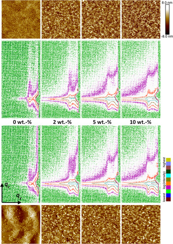
Figure 4. (Color online) GISAXS patterns of 20 nm films of DiBCP with different concentration of Fe3O4 NP (miscoloured contour plot log(I), mesh size Δq = 0.1 nm−1). Above: as dip-coated, below: after SVA with THF. AFM height images (image size 2 × 2 µm2). On top: as dip-coated, at the bottom: after SVA with THF.
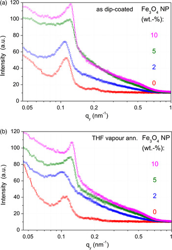
Figure 5. (Color online) Out-of-plane curves of GISAXS patterns in Figure 4 at q z = q Yoneda,DiBCP–NP (α i = 0.30°); (a) above – as dip-coated, (b) below – THF vapour annealed.
Table I. Summary of applied NP and their parameters, DiBCP films and their morphology characterization with AFM and GISAXS (lateral correlations).

All parameters are rounded.
a a hex can be calculated exactly only in the case of HCPC in the film (Lee et al., Reference Lee, Park, Yoon, Park, Kim, Kim, Chang and Ree2005).
b For surface modifications, see: Synthesis of NP. 〈Ø〉 – mean core diameter. not. def. – not definable. n.m. – not measured.
Fe3O4 NP cause a strong diffuse background in the GISAXS patterns and do not show a significant preference for any block. Obviously, the background is caused by the NP themselves (with iron as strong scattering element). Fe3O4 NP segregate to the polymer/substrate (silicon wafer) interface. The presence of Fe3O4 NP at the polymer/substrate interface induces a strong domain orientation effect in both as-cast and SVA films, which is attributed to the changes of the effective substrate energy (Horechyy et al., Reference Horechyy, Nandan, Zafeiropoulos, Jehnichen, Göbel, Stamm and Pospiech2014).
It can also be noted that the cylindrical morphology of the DiBCP remains unaltered after incorporation of Fe3O4 NP. However, increasing amount of Fe3O4 leads to an enhanced ratio between standing and lying cylinders. Another interesting aspect of the DiBCP/Fe3O4 system is that the distance between the PMMA cylinders is reduced after NP addition.
The treatment of pure DiBCP films with THF vapour does not improve the order as it was found for other DiBCP (Gu et al., Reference Gu, Gunkel, Hexemer, Gu and Russell2014; Zhang et al., Reference Zhang, Posselt, Smilgies, Perlich, Kyriakos, Jaksch and Papadakis2014; Sepe et al., Reference Sepe, Zhang, Perlich, Smilgies, Posselt and Papadakis2016). Annealing of pure DiBCP films with THF vapour leads to the formation of islands of dot-like structures within feature-less regions. This can be explained to be a result of incommensurate of film thickness with respect to the DiBCP domain spacing (Fasolka et al., Reference Fasolka, Banerjee, Mayes, Pickett and Balazs2000). For comparison, the use of CHCl3 in solvent annealing of DiBCP thin films (without NPs) induces substrate-parallel orientation of PMMA domains, as discussed in a former work by Horechyy et al. (Reference Horechyy, Nandan, Zafeiropoulos, Jehnichen, Göbel, Stamm and Pospiech2014). A very interesting observation was that upon addition of Fe3O4 NP the effect of SVA on the resulting morphology is quite similar: the initial surface morphology formed upon film deposition (as-cast samples) remains almost unchanged before and after exposure to the solvent vapours, irrespective whether THF or CHCl3 was used. At lower Fe3O4 NP content (2 wt.%), a mixture of standing and short laying cylinders can be seen, whereas at higher NP loading (>5 wt.%) standing cylinders prevail before and after SVA. Dominating perpendicular domain orientation, subsequently, leads to the reduced periodic distance, which can be noticed from the analysis of GISAXS results [see Figures 5(a) and 5(b) and Table I]. These observations suggest that in the DiBCP/Fe3O4 system Fe3O4 NP acts as structure-directing and, at the same time, structure-freezing additives. Such effects were discussed in thin films of lamellae-forming polystyrene-b-polybutadiene DiBCP systems (Berezkin et al., Reference Berezkin, Papadakis and Potemkin2016) as well.
Additionally, for selected samples of the DiBCP/NP system with different content of Fe3O4 NP magnetic measurements were performed. Figure 6 shows the magnetization loops for NP-free (0 wt.%) and NP-containing polymer films (2 and 10 wt.% nominal NP concentration) as a function of the applied magnetic field. The raw data of the NP-free film (0 wt.%, inset) display the diamagnetic slope from the substrate and a small ferromagnetic contribution from the sample holder. They have been fitted and used as a background correction for the NP-containing samples. The NP-containing films show a clear magnetic signal, which is essentially saturated at 1 T. Within the field resolution of the measurement, the coercivity of the samples is negligible, which is in agreement with the superparamagnetic behaviour known for these magnetic NPs.

Figure 6. (Colour online) Normalized magnetization of DiBCP films with different content of Fe3O4 NP, after subtraction of the background signal measured in the NP-free sample (inset) as function of the applied field in the film plane.
Looking at the slightly different approach to saturation, one observes that in the higher concentrated NP film the magnetostatic interactions lead to an increase of the magnetic order (increased initial susceptibility), which is opposite to the typically observed increased disorder in more dispersed systems of interacting magnetic NP systems (e.g., granular metallic alloys Cu90Co10 discussed by Allia et al. (Reference Allia, Coisson, Tiberto, Vinai, Knobel, Novak and Nunes2001)). There, the behaviour is determined also by the strong non-magnetic interaction of two metallic components (diamagnetic Cu and ferromagnetic Co) and is in this respect incommensurable to a system polymer matrix with ferromagnetic Fe3O4. Nevertheless, it could be shown that already in very thin DiBCP films with only low amount of Fe3O4 NP magnetization is present and can be measured. The superparamagnetic behaviour proves that the inserted Fe3O4 NP are small enough and have a sufficient mobility in the DiBCP matrix to turn in magnetic fields.
b. Influence of the solvent used in SVA
To get more information about the interaction of the polymer blocks (PMA) n and (MMA) m with the solvents used in SVA (THF and CHCl3), calculations of phase diagrams were performed in order to find out whether the solvents are selective or not related to the blocks of PPMA-b-PMMA. This knowledge is helpful to understand the structure formation and its changes in the thin films.
The results, illustrated in Figure 7, show 2D cuts through the 3D phase diagram (not presented) of the polymer–solvent mixture of the DiBCP PPMA-b-PMMA (70/30 mol mol−1) with the solvents THF and CHCl3, respectively (0–100 vol.% solvent). The horizontal line marks the composition of investigated DiBCP with molar mass of 184 kg mol−1 (degree of polymerization, DP = 1320).
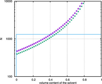
Figure 7. (Color online) Phase diagram of the three component system, containing the DiBCP PPMA-b-PMMA and one solvent (![]() – THF;
– THF; ![]() – CHCl3). Additionally inserted is the line (
– CHCl3). Additionally inserted is the line (![]() ) representing the investigated DiBCP with molar ratio 70/30 (PMA/MMA) and molar mass of 184 kg mol−1 (DP = 1320) – profile across the three component spinodal hypersurface (3D triangle diagram: PMA–MMA–solvent) along the line of 100%-DiBCP to 100%-solvent.
) representing the investigated DiBCP with molar ratio 70/30 (PMA/MMA) and molar mass of 184 kg mol−1 (DP = 1320) – profile across the three component spinodal hypersurface (3D triangle diagram: PMA–MMA–solvent) along the line of 100%-DiBCP to 100%-solvent.
The label of the y-axis is N, and not χ·N as in usual phase diagrams because different interaction parameters χ of the polymer blocks to the solvent have to be assumed. The three-component system contains three different interaction parameters χ (Table II). The shown spinodal lines represent the first step of the phase separation in the DiBCP solution. The first step of separation originates from the system with the larger χ. In the present case, the first step results from demixing of the MMA block with the solvent. Therefore, the phase separated region above the first step spinodal line is biphasic and contains a phase with the DiBCP and a mixed phase with PMA/solvent. A second step of phase separation would lead to a three phase region above the second spinodal line and is caused by the next smaller χ parameter, resulting in the PMA enriched phase, the PPMA-b-PMMA phase and the solvent phase. Only now, the third separation step can occur, where the PMA block of the DiBCP separates from the MMA block in the thin film.
Table II. Results of χ parameter calculations performed for the binary systems polymer block/solvent and block/block of the DiBCP and solvents under investigation.

Because of the fact that only the first step of phase separation is available for calculations in the 3D phase diagram the calculations were complemented by providing 2D spinodals of blends consisting of the corresponding PMMA-b-PMMA, homopolymers, and solvents (Figure 8). In summary, Figure 8 shows that CHCl3 is more selective to the different blocks PPMA and PMMA (spinodals located below those of THF). Generally, it can be seen that only the area of lower volume content (up to about 0.4) leads to a phase separation. Outside of this area the homopolymer blocks seems to be fully solvated. Otherwise, the mixture of PPMA and THF does not show any spinodal according the calculation approach applied here, i.e. it is a mixture across the full area.
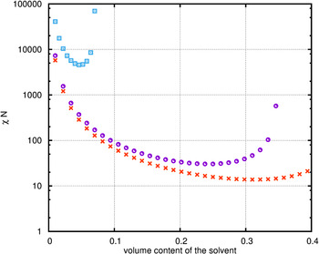
Figure 8. (Color online) Phase diagram of a two component systems, containing one homopolymer (PPMA or PMMA, respectively) and one solvent (THF or CHCl3, respectively); ![]() – PMMA/THF,
– PMMA/THF, ![]() – PMMA/CHCl3,
– PMMA/CHCl3, ![]() – PPMA/CHCl3.
– PPMA/CHCl3.
It can be concluded from the calculations that the interaction of both solvents with the DiBCP is qualitatively equal. Quantitative differences are small. In the case of CHCl3 a stronger influence, i.e. a little bit higher selectivity may be stated ending up with a microphase-separated structure formation of the block copolymer inside the thin film.
c. Thin films with SiO x NP
In a second sample series, the morphology in thin DiBCP films with different amounts of SiO x NP were compared in dependence on their NP content and on the film treatment (as-prepared/dried and after SVA with THF). This comparison is presented in Figure 9 as an overview of GISAXS patterns and AFM images. The parameters of the lateral correlations of the film morphology as observed in the out-of-plane curves [Figure 10(a) and 10(b)] and results of the PSD in the AFM images are summarized in Table I.

Figure 9. (Color online) GISAXS patterns of 35 nm films of DiBCP with different concentration of SiO x NP (miscoloured contour plot log(I), mesh size Δq = 0.1 nm−1). Above: as dip-coated, below: after SVA with THF. AFM height images (image size 2 × 2 µm2). On top: as dip-coated. 0 wt-%*) – reference film (pure polymer solution); 0 wt-% – film from solution after in-situ process without precursor.
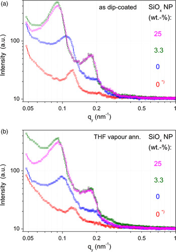
Figure 10. (Color online) Out-of-plane curves of GISAXS patterns in Figure 9 at q z = q Yoneda,DiBCP–NP (α = 0.30°); (a) above – as dip-coated, (b) below – THF vapour annealed.
In this work, a special kind of NP generation was applied. The in situ generation of SiO x NP in a sol–gel process was exploited to realize a large range of NP concentration (up to 25 wt.%). To get reliable information about the influence of the NP amount, a thin film with 0 wt.% SiO x was prepared from DiBCP solution without the TEOS precursor, but undergoing all other treatments of the sol–gel process. In comparison with a DiBCP film dip-coated only with THF solution, a moderate increase of the d-spacing and a broadening of the lateral correlation peaks was found in the treated film. After evolution of the SiO x NP (3.3 and 25 wt.%, respectively), a strong enlargement of d-values was detected. Interestingly, there is no significant difference between the samples with different NP amounts. However, the SiO x amount could not be determined directly, it was only calculated from the starting concentration in the DiBCP solution. SVA with THF does not change the result. GISAXS 2D pattern (Figure 9) and their out-of-plane curves [Figures 10(a) and 10(b)] show these changes. Apparently, at the end of the sol–gel process after annealing the film morphology was as perfect as possible under these conditions, so that an additional SVA does not initiate further improvements.
The HCPC morphology can only be confirmed in the case of standing cylinders. SiO x NP (by in situ sol–gel process) cause a quite strong influence on the film morphology as observed by AFM. Higher concentration of SiO x results in the change between standing to PMMA cylinder morphology. AFM images show that a high concentration of SiO x extends the cylinder length. This indicates that SiO x is incorporated into the PMMA cylinders and improves the morphology, which is because of the high polarity of both, SiO x and PMMA. The extension of cylinder length could be explained by a post-condensation of SiO x NP in cylinder direction. The broadening of the lateral correlation peaks can be explained by the enhanced amount of lying cylinders and the enhanced length of the PMMA cylinders. An additional segregation of SiO x NP on the silicon wafer surface cannot be excluded. However, an evidence of that is difficult.
This behaviour is different from the result found by stepwise off-line treatment of pure DiBCP films with TEOS, followed by treatment with H2O/HCl vapour (Jehnichen et al., Reference Jehnichen, Pospiech, Friedel, He, Zhang, Sepe, Papadakis, Taurino and Perlich2015). In this method of NP generation, a rather weak decrease of the d-values was found. Here the generation of SiO x is going on in different steps of the SVA process. It was observed that only a relatively low amount of small SiO x particles can be generated. The out-of-plane curves are broadened indicating a significant change in morphology. The morphology of the initially prepared well-nanostructured thin film of the pure DiBCP cannot be maintained by this method. This was only possible when DiBCP with –OH end groups were employed. After conversion of –OH into triethoxysilane groups, SiO x NP were generated by the DiBCP template (Werner et al., Reference Werner, Pospiech, Jehnichen, Eckstein, Komber, Friedel, Janke, Näther, Reuter, Voit, Taurino and Messori2011).
d. Thin films with metallic NP
In continuation of the studies, a few thin films with organo-modified Au and Ag NP, respectively, were prepared and investigated in a similar manner. GISAXS and AFM figures are not shown here. But the final results based on GISAXS and AFM measurements are inserted in Table I as well.
In comparison to the pure DiBCP film with 51.5 nm (d 100 reflection), in films with organo-modified metallic NP a strong reduction of this value was observed (minus ~7 nm and minus ~12 nm for Au NP and Ag NP, respectively). Former investigations with similar DiBCP films and metallic NP (DDT-modified according to the same procedure) have shown only a moderate decrease in presence of Au NP (Jehnichen et al., Reference Jehnichen, Pospiech, Friedel, He, Zhang, Sepe, Papadakis, Taurino and Perlich2015). In this case, the mean core diameter of Au NP was significantly smaller (2 nm) in contrast to the actual one (10 nm). With Ag NP (mean core diameter 7.5 nm), the reduction of the d 100-value is much stronger with slight increase at higher NP content compared with the Au NP. The reduction of the domain spacings is caused by the preferential interaction of the Au NP with PMMA cylinders (Kim et al., Reference Kim, Bang, Hawker and Kramer2006; Yoo et al., Reference Yoo, Kim, Jang, Choi, Yang, Kramer, Lee, Kim and Bang2011; Jehnichen et al., Reference Jehnichen, Pospiech, Friedel, He, Zhang, Sepe, Papadakis, Taurino and Perlich2015). Otherwise, there is a strong influence of the NP interaction with DiBCP matrix dependent on the surface modification of the NP. For instance, it could be demonstrated for Au NP that a modifying with polyoxymethylene leads to a segregation of the Au NP at the film/substrate interface (He, Reference He2014).
IV. CONCLUSION
Summarizing the results of the previous and current studies that were carried out using a method combination of SAXS, XRR, and GISAXS about the influence of modified NP with PPMA-b-PMMA DiBCP in thin films, it can be stated that the NPs induce distinct morphology changes.
The changes of the DiBCP morphology depend strongly on the type of NP, their size, the chemistry of the modifying shell used to stabilize the NP, but also on the thickness of the DiBCP film and the solvent used for preparation. This behaviour reflects the complex interplay between the interfacial tensions of all components in the system. Moreover, the surface tension of the underlying substrate (here the silicon wafer) plays an important role. Therefore, it is indispensable to keep all preparation parameters and NP characteristics constant before more general aspects of the influence of a certain type of NP can be derived.
Assuming these constant parameters, the following notices can be summarized:
Fe3O4 NPs stabilized with sparse aliphatic shell brought into the standing cylinder structure of the DiBCP in the thin film tend to reduce the d-spacing of the DiBCP morphology at a certain minimum concentration of 5 wt.%. Fe3O4 NP segregate to the polymer/substrate interface and stabilize the standing cylinder morphology.
In contrast, SiO x NP (without chemical modification and with high density of polar –OH groups at the surface) are generated within the PMMA cylinder phase because of the higher polarity of PMMA compared with the PPMA matrix. Thus, the PMMA cylinders swell and enlarge the DiBCP d-spacing. Higher concentrations of SiO x result in the change of standing PMMA cylinder morphology to lying cylinder morphology where the cylinders are aligned parallel to the substrate. Concentration of about 25 wt.% causes the expansion of PMMA cylinder lengths of about 2 µm and create very stabilized morphologies.
Au NPs were stabilized with dodecyl alkyl shells. For that reason, they segregate to the interface between the PMMA cylinders and the PPMA matrix and cause the reduction of the d-spacing of the BCP. Low amounts of Au NP stabilize the standing cylinder morphology, while at higher amounts the NP segregates to the substrate as in the case of Fe3O4.
Solvent annealing in the given DiBCP system does not mostly improve the morphology of the DiBCP/NP nanocomposites, which is because of the fact that only weak preferential interactions between one of the blocks and the solvent (either THF or CHCl3) can be assumed as the calculations of phase diagrams of the solutions showed.
The combination of GISAXS and AFM investigations gave the possibility to find out the complex behaviour of the system DiBCP/NP under the conditions of thin-film preparation and subsequent treatment by SVA. Mixed morphologies, i.e. varying amount of standing and lying cylinders of PMMA in the PPMA matrix, were found more often as expected from the chemically tailored DiBCP and the realized parameters of the dip-coated thin films.
It can be stated that the multiphase systems implements a huge interplay of interactions between all components under either stable or varying conditions during all processes starting at synthesis and closing with the final thin film as matter of complex measurements which should offer the true morphology. The results have to be verified and challenged. New methods of investigations, better resolved data and modelling of structure parameters and interaction force can be helpfully.
To achieve more or less identical films other parameter and conditions should be taken into account, e.g. type and power of interaction forces, energetic conditions at interfaces, enthalpic contributions, and further more. On the other side, in such multiphase systems (wafer having hydrophobic or hydrophilic surface, two different polymer blocks, solvent – selective or non-selective related to the polymer blocks, different surface-modified NP) a lot of scenarios can be designed.
ACKNOWLEDGEMENTS
We thank all not-named colleagues of the IPF, participating in synthesis and characterization of polymers. We gratefully acknowledge financial support by and participation in EU NoE “NANOFUN-POLY” and by the German Science Foundation. We thank HASYLAB @ DESY Hamburg (now: DESY Photon Science) for carrying out scattering experiments as well as the beamline operators and technicians for their help to perform the experiments.


