I. INTRODUCTION
Double-bent-crystal (DBC) monochromator settings are not very commonly exploited in neutron diffractometry. Nondispersive as well as dispersive DBC monochromators are quite common at synchrotron sources. However, in the case of neutrons, at present, one can find only several scattering instruments in the world which use nondispersive double-crystal settings for neutron monochromatization (e.g. HB-1A Triple-Axis Spectrometer at High Flux Isotope Reactor in ORNL, Double Crystal Diffractometer at NIST for USANS, 4F1, and 4F2 spectrometers in LLB Saclay). The goal of such a setting on the diffractometer's performance was to decrease the neutron background, namely, in the case when the instrument was installed at the reactor. When the instrument is installed at the neutron guide, the problem of the background becomes unimportant, however, any use of the double crystal monochromator with mosaic crystals brings about a decrease in the luminosity of the instrument, because the peak reflectivity of each mosaic crystal is usually much less than 100%. When using perfect single crystals, double crystal settings have often been used for high-resolution experiments, namely, in the field of dynamical diffraction. The situation is considerably different in the case of employing bent perfect crystals (BPC), when the peak reflectivity depends on the crystal material and the crystal curvature (Kulda, Reference Kulda1984; Mikula et al., Reference Mikula, Kulda, Vrána and Chalupa1984). First, DBC settings have been used in high or medium resolution SANS diffractometers with a variable resolution (Kulda and Mikula, Reference Kulda and Mikula1983; Mikula et al., Reference Mikula, Lukáš and Eichhorn1988; Šaroun et al., Reference Šaroun, Lukáš, Mikula and Alefeld1994; Hempel et al., Reference Hempel, Eichhorn, Reichel and Boede1996). Recently, several experimental studies into properties of dispersive DBC settings have been carried out, with the goal of their possible employment in high resolution diffractometry (Mikula et al., Reference Mikula, Vrána, Šaroun, Pilch, Seong, Woo and Em2014, Reference Mikula, Vrána and Korytár2015; Mikula and Vrána, Reference Mikula and Vrána2015). The tested DBC settings demonstrated the possibility of obtaining a high-resolution monochromatic beam with a very low collimation (2Δ θΜ) and Δ θ spread without using any Soller collimators. In the present paper, we describe the properties of dispersive DBC settings of Si(111) + Si(311) and Si(111) + Si(400) with the fully asymmetric diffraction (FAD) geometry and a strongly asymmetric diffraction geometry of the second crystal analyzer, respectively, when the analyzer was oriented for the output beam compression (OBC) geometry. Figure 1 shows schematic drawings of the DBC performances employing BPCs as used in the experiment with a powder standard sample of α-Fe(211). The experiment was carried out on the neutron optics diffractometer installed at the medium power research reactor LVR-15 in Řež and operating at the constant neutron wavelength of 0.162 nm. The diffractometer can operate in two or three axis mode and permits a variety of neutron diffraction experiments to be carried out. All Si crystals had the following dimensions: 200 × 40 × 4 mm3 (length × height × thickness). It should be pointed out that the radius of the curvature of the first Si(111) crystal of the DBC setting was fixed (R 1 ≈ 12 m) and was not changed during the experiment. No Soller collimator was installed before or after the first Si(111) crystal. In order to be sure that all neutrons from the Si(111) crystal were incident on the second crystal, the height of the slit (see Figure 1) was 20 mm and was not changed during the experiment.

Figure 1. (Color online) The DBC setting with the symmetric diffraction geometry of the first crystal and (a) the FAD-geometry of the second Si(311) crystal or (b) the asymmetric geometry of the second Si(400) crystal. Both cases used OBC orientation.
II. DBC SETTING WITH THE SECOND Si(311) CRYSTAL IN THE FAD-OBC GEOMETRY
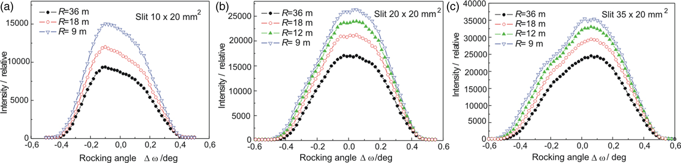
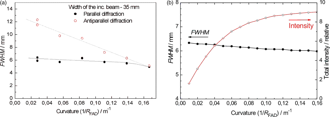
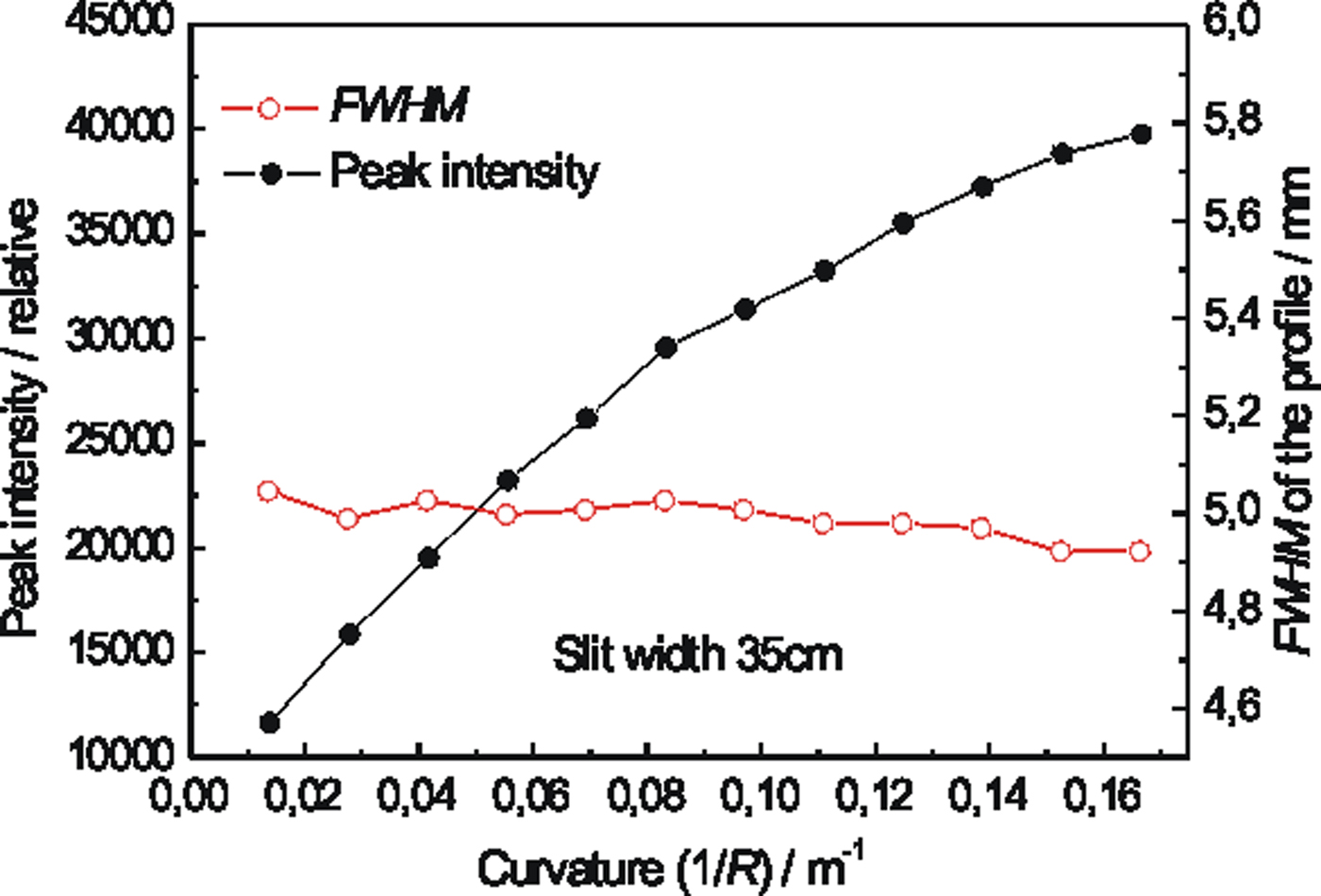
First, double crystal rocking curves were measured in order to find out if there is an effect and how large the effect is of the width of the incident beam on the luminosity of the obtained double diffracted beam after the second crystal. Figure 2 shows the rocking curves obtained by the rotating of the second FAD-crystal (see Figure 1(a)) in the vicinity of the Bragg condition for Si(311) lattice planes with respect to the first crystal for three widths of the incident beam. It is evident that when the larger width of the incident beam is used a higher intensity of the double reflected beam (measured by the peak intensity of the rocking curves) can be obtained. Slight asymmetry of the rocking curves seen in Figures 2(a) and 2(c) is brought about by a combination of spatial inhomogeneity of the beam incident on the second crystal and the attenuation of Si slab for neutrons passing along its longest edge. As in the further investigations just the peak position of the double-crystal rocking curve was used, its asymmetry had negligible influence on the powder diffraction profiles. Therefore, in the next step, the intensity of the double diffracted beam for peak position on the rocking curve (Δ ω = 0o) as well as the full width at half maximum (FWHM) of the output beam profile as a function of the crystal curvature 1/R FAD was measured by means of a scintillation camera (SC) at the distance of 50 cm from the second crystal. Figure 3 shows the obtained parameters of the imaged profiles. From Figure 3 an appealing beam property can be seen, where for the largest curvature of the crystal, a minimum FWHM (slightly less than the crystal thickness of 4 mm) and simultaneously a maximum peak intensity of the profiles were obtained. After the preparation of the monochromatic beam by the double diffraction process, its resolution properties were tested on the standard α−Fe(211) polycrystalline pin, of 2 mm diameter, situated just 50 cm from the FAD-crystal. The tests were carried out in both, so-called parallel and antiparallel, diffraction geometries (see Figure 1(a)) and for two widths of the incident beam. Figure 4 shows examples of the powder diffraction profiles displayed by means of the Imaging plate (IP) placed at 50 cm from the α-Fe(211) pin. It documents a high-resolution property for both geometries. The estimation provides the values of FWHM(Δ d/d) at about 3 × 10⁻³, 5 × 10⁻³, 9 × 10⁻³, 9.4 × 10⁻³ for the results shown in Figures 4(a), 4(b), 4(c), and 4(d), respectively. Figure 5(a) summarizes the related results of FWHM for different curvatures of the FAD slab and for the incident beam-slit width of 35 mm. In the case of parallel diffraction position, Monte Carlo simulations (Šaroun and Kulda, Reference Šaroun and Kulda2009) were also carried out which showed a similar behaviour of the FWHM as a function of the FAD-crystal curvature (see Figure 5(b)).

Figure 2. (Color online) Double-crystal rocking curves of the FAD crystal for different radii of curvature R and different widths of the beam incident on the second crystal: (a) 10 mm, (b) 20 mm, (c) 35 mm.
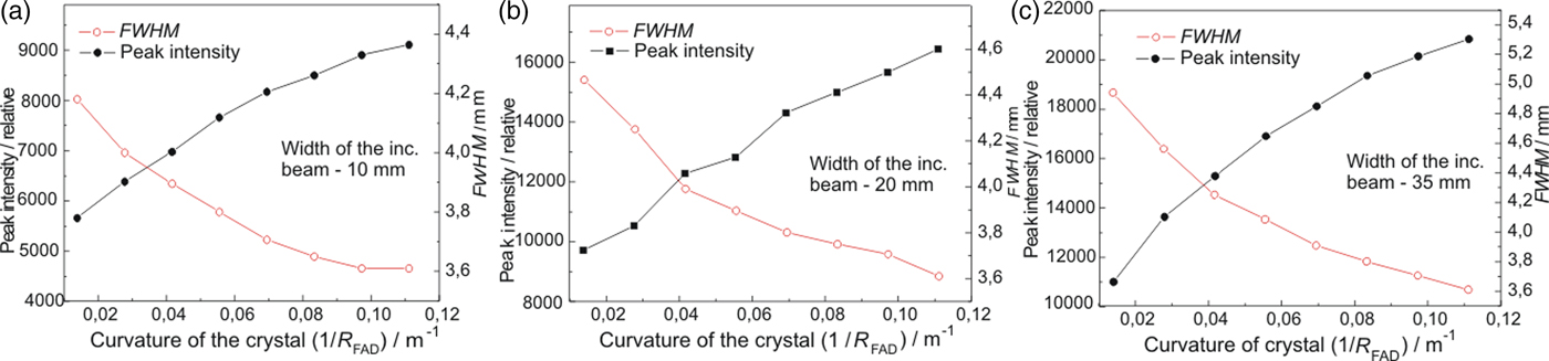
Figure 3. (Color online) Properties of the output beam profiles from the FAD crystal as a function of the crystal slab curvature imaged by scintillation camera for different widths of the beam incident on the second crystal: (a) 10 mm, (b) 20 mm, (c) 35 mm.

Figure 4. Examples of the diffraction profiles from the α-Fe(211) polycrystalline pin in the parallel and antiparallel diffraction geometry for two widths of the incident beam slit as taken by the Imaging plate.

Figure 5. (Color online) The summarized results of FWHM for different curvatures of the FAD crystal slab and for the incident beam-slit width of 35 mm (a), and the result of the Monte Carlo simulation for the parallel diffraction geometry (b).
III. DBC SETTING WITH THE SECOND Si(400) CRYSTAL IN A STRONGLY ASYMMETRIC TRANSMISSION GEOMETRY
In this case we used the Si crystal slab cut with the lattice planes (111) parallel to the main surface. Then, the planes (400) were at the angle of 54.7° with respect to the main surface of the slab. As the related Bragg angle is equal to 36.7°, we could test properties of a strongly asymmetric diffraction geometry as schematically shown in Figure 1(b). First, we measured the Si(400) rocking curves and then the profiles of the beam reflected by the second crystal by a SC (measured at the peak position of the rocking curves) for different curvatures of the Si(400) crystal slab (see Figure 6). The properties of the beam profiles are summarized in Figure 7. It can be seen from Figure 7 that with increasing crystal curvature the beam intensity strongly increases but FWHM of the beam profile decreases only very slightly. In the next step, the diffraction profiles from the α-Fe(211) polycrystalline pin (2 mm diameter) were measured by IP for parallel (see Figure 8) as well as antiparallel (see Figure 9) diffraction geometry. In this case, a large difference of FWHM of the profiles in parallel and antiparallel geometry is evident. An estimated minimum resolution FWHM(Δ d/d) of about 11 × 10−3 for parallel diffraction geometry can also be considered as good. However, the smallest curvature of the Si(400) slab yields the smallest luminosity. Finally, Figure 10 summarizes the results of FWHM for different curvatures of the Si(400) slab.
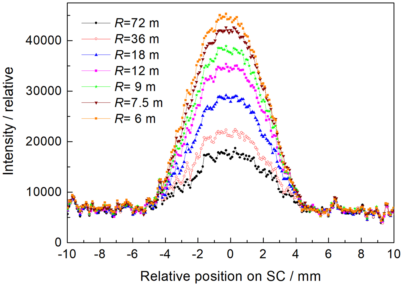
Figure 6. (Color online) Profiles of the output beam from the Si(400) crystal as imaged by scintillation camera at the distance of 50 cm for different radii of curvature R at the peak position of the rocking curve and the slit width of 35 mm.

Figure 7. (Color online) Summarized properties of the output beam profiles from Figure 6 as a function of the crystal curvature.
Figure 8. Examples of the diffraction profiles from the α-Fe(211) polycrystalline pin as taken by Imaging plate at 50 cm for different curvatures of the Si(400) slab, 35 mm slit and parallel diffraction geometry.
Figure 9. Complementary examples to the previous ones from Figure 8 of the diffraction profiles from the α-Fe(211) polycrystalline pin for different curvatures of the Si(400) slab, 35 mm slit and antiparallel diffraction geometry.

Figure 10. Summarized FWHMs of the beam profiles from the polycrystalline pin for both diffraction geometries as a function of the curvature of the second bent perfect crystal (BPC) slab.
IV. SUMMARY
In this paper, neutron diffraction properties of the (quasi)-dispersive double-crystal Si(111) + Si(311) and Si(111) + Si(400) settings containing two BPCs with the second in the strongly asymmetric diffraction geometry, were investigated. The quasi-dispersive DBC arrangements provide a highly parallel monochromatic beam. The width of the output beam from the second crystal can be in the range of several millimetres. It was demonstrated that a narrow monochromatic beam can be exploited in high-resolution powder diffractometry. However, it should be pointed out that the quasi-dispersive experimental performances have such excellent properties in one dimension only, i.e. in the scattering plane. As it is usual in the case of BPCs, the resolution can be easily manipulated by changing the curvature of the employed crystals. Finally, it should be pointed out that there is still one more free parameter – the curvature of the first Si(111) slab which was fixed in our case. It is possible that changes in the Si(111) curvature could improve the optimization of both crystals in the DBC system.
ACKNOWLEDGEMENTS
Measurements were carried out at the CANAM infrastructure of the NPI CAS Řež supported through MŠMT project No. LM2015056. The presented results were also supported in the frame of LM2015074 infrastructural MŠMT project “Experimental nuclear reactors LVR-15 and LR-0”. Bragg diffraction optics investigations are in the Czech Republic, supported by GACR project No. 16-08803J and by the ESS project LM2010011: “Contribution to Partnership in Large Research Infrastructure of Pan-European Importance”. The authors thank Ms. Michalcova from NPI ASCR for significant help in the measurements and basic elaboration of the data.