I. INTRODUCTION
Rietveld-based quantitative X-ray diffraction (QXRD) allows an accurate estimation of changes in the mineralogical composition of solids or slurries. The application of QXRD analysis has been used extensively in research of hydrometallurgical processes, particularly the reaction chemistry and kinetics of ore leaching (Scarlett et al., Reference Scarlett, Madsen and Whittington2008; Wang et al., Reference Wang, Li, Hart, van Riessen and McDonald2011, Reference Wang, McDonald, Hart, Li and van Riessen2014). The formation of new phases as a result of precipitation is often encountered during ore leaching processes, especially under high-temperature conditions, and the formation of these phases can be monitored by the QXRD analysis (Whittington et al., Reference Whittington, Johnson, Quan, McDonald and Muir2003b; Madsen et al., Reference Madsen, Scarlett and Whittington2005). In this work, two case studies are discussed to demonstrate how Rietveld-based QXRD can be applied to improve understandings of ore processing and mineral formation.
Case One: Nickel laterites contain ~70% of the world's land-based nickel resources, whereas sulphides contain the remaining ~30% (Dalvi et al., Reference Dalvi, Bacon and Osborne2004). With the rapid depletion of the nickel sulphide resources, global production of nickel from laterite ores has increased from 42% in 2003 (Dalvi et al., Reference Dalvi, Bacon and Osborne2004) to ~56% in 2012, overtaking the production from sulphide ores. Western Australia (WA) hosts approximately 90% of the total Australian economic nickel resources (Geoscience Australia, 2012). Some of the laterite ore which deposits in WA are located in the close proximity to sulphide ore deposits, offering a potential opportunity for the co-processing of oxidic and sulphidic materials (Quinn et al., Reference Quinn, Turner, van der Meulen, Malhotra, Taylor, Spiller and LeVier2009). Traditionally high-pressure acid leaching (HPAL) has been commercially applied to nickel laterite ores (Whittington and Muir, Reference Whittington and Muir2000). In co-processing, nickel laterite and sulphidic materials (e.g. nickel sulphide concentrates) are mixed and processed under HPAL conditions (McDonald et al., Reference McDonald, Rodriguez, Li, Robinson, Jackson, Hosken, Collins, Filippou, Harlamovs and Peek2012). This blending can improve the rheology of the pulp as compared with laterite ore processing (Rodriguez, Reference Rodriguez2009), with addition of an oxidant enabling in situ sulphuric acid production with co-generation of heat, improving overall nickel recovery and, potentially enabling the processing of “dirty” concentrates (e.g. containing As, Sb, and Hg) and concentrates obtained from disseminated sulphide ores (McDonald et al., Reference McDonald, Rodriguez, Li, Robinson, Jackson, Hosken, Collins, Filippou, Harlamovs and Peek2012). The reaction chemistry during co-processing is complex and not well understood, and the aim of the current study was to better understand the oxidation of the sulphide minerals. Changes to the iron hydrolysis chemistry during co-processing were also investigated.
Case Two: Solutions rich in ferrous iron (Fe2+) are generated during oxidative leaching of sulphide ores and reductive leaching of oxide ores (Ozkaya et al., Reference Ozkaya, Sahinkaya, Nurmi, Kaksonen and Puhakka2007; Nurmi et al., Reference Nurmi, Ozkaya, Kaksonen, Tuovinen, Riekkola-Vanhanen and Puhakka2009; du Plessis et al., Reference du Plessis, Slabbert, Hallberg and Johnson2011). The subsequent oxidation of Fe2+ to ferric iron (Fe3+) and precipitation of Fe3+ from the leach solutions are required to remove excess iron that can passivate mineral surfaces and interfere with valuable metals recovery. Biologically catalysed Fe2+ oxidation is preferred over abiotic oxidation, as it is several orders of magnitude faster than abiotic oxidation at low pH (Rawlings, Reference Rawlings2002). In this study, a two-stage reactor configuration recently proposed by du Plessis et al. (Reference du Plessis, Slabbert, Hallberg and Johnson2011) was used for biological Fe2+ oxidation and subsequent Fe3+ precipitation as jarosite. The aim of this work was to use QXRD to confirm the formation of jarosite, to determine the crystallinity, and the incorporation of cations in the jarosite structure.
II. EXPERIMENTAL
A. Materials and methods
Case One: Details of the materials and experimental procedures can be found elsewhere (McDonald et al., Reference McDonald, Rodriguez, Li, Robinson, Jackson, Hosken, Collins, Filippou, Harlamovs and Peek2012). Briefly, the nickel laterite ore, obtained from the Bulong complex, 40 km east of Kalgoorlie in WA, was ball milled and wet screened to −500 μm. A Poseidon nickel concentrate sample was dry screened to −75 μm. Tests using just the Poseidon nickel sulphide concentrate were run using 10% (w/w) pulp density, whereas those with only Bulong nickel laterite employed 30% (w/w) pulp density. For blends of Bulong nickel laterite with Poseidon nickel concentrate, the ratio of concentrate to laterite was calculated, so that sufficient in situ sulphuric acid was formed to leach the laterite ore. A series of feeds were leached at 250 °C using a 1 gal. Parr titanium autoclave and Poseidon site process the water (Na+ 3.1, K+ 0.08, Mg2+ 0.33, Ca2+ 0.11, SO42− 0.89, Cl− 5.3, g l−1). The oxidation of the concentrate was enabled via the continuous, controlled injection of oxygen to give a head space partial pressure of 100 kPa. The autoclave contents were sampled as slurry collected after 10, 20, and 30 min reaction time, and every 15 min thereafter; the total reaction time was 90 min for each test. After leaching, the slurries were filtered and the residues were washed, repulped, refiltered, and dried overnight in an oven set at 70 °C. The washed residues and leach solutions were submitted for the elemental analysis by inductively coupled plasma-optical emission spectroscopy (ICP-OES). Sulphur analyses were performed using a LabFit CS-2000 analyser. A selection of residues was submitted for the XRD analysis.
Case Two: Details of the microbial inoculum, the bioreactor setup, sampling, and subsequent analytical methods have been described in Kaksonen et al. (Reference Kaksonen, Morris, Suzy, Li, Wylie, Usher, Ginige, Cheng, Hilario and du Plessis2014a, Reference Kaksonen, Morris, Suzy, Li, Usher, McDonald, Hilario, Hosken, Jackson and du Plessis2014b). Briefly, a two-stage continuous stirred tank reactor (CSTR) system as illustrated in Figure 1 was assembled for iron oxidation and precipitation at room temperature (23 ± 2 °C). A mixed culture of iron oxidizing micro-organisms was applied to assist ferrous oxidation inside the reactors. The influent of the system contained 15 g l−1 Fe2+ and the pH was adjusted to 1.0, 1.5, 1.9, and 2.2 for each test. Influent was fed with a peristaltic pump into the CSTR1 from which it flowed under gravity to the first settler. The overflow from the first settler was directed by the peristaltic pump to the CSTR2 from which the solution flowed by gravity to the second settler (Figure 1). The effluent from the second settler flowed by gravity to an effluent container. Sludges from settlers 1 and 2 were recycled back into CSTR1 and CSTR2, respectively. Excess sludge was intermittently removed from the settlers using a peristaltic pump. Sludge removed from the settlers was collected to analyse the elemental and mineralogical compositions of the precipitates and for the scanning electron microscopy (SEM). The CSTR influents and effluents were sampled for pH, Fe2+, and soluble Fe analysis.

Figure 1. (Color online) Schematic representations for two-stage continuous stirred tank reactor (CSTR) system (Kaksonen et al., Reference Kaksonen, Morris, Suzy, Li, Wylie, Usher, Ginige, Cheng, Hilario and du Plessis2014a).
B. Data collection and analysis for XRD
The mineralogy of the solid samples was examined by the XRD analysis. The XRD traces were obtained after addition of calcium fluoride [CaF2, to yield 10% (w/w)] as internal standard and micronized in the ethanol medium for 15 min. The micronized sample was air-dried and lightly reground before back-pressing into a conventional XRD sample holder. XRD measurements were carried out using a PANalytical X'Pert PRO diffractometer in Bragg–Brentano geometry equipped with a Co long fine focus tube source operated at 40 kV and 40 mA. The beam path was defined with a 1° divergent, 0.3 mm receiving and 1° anti-scatter slits. A post-diffraction, curved graphite monochromator was used to eliminate Kβ radiation. Patterns were recorded from range of 3 to 140°2θ using a step size of 0.02° and a counting time of 2.5 s per step. Commercially available TOPAS (version 4.2) software (Bruker Advanced X-ray Solutions) was employed to perform the QXRD analysis using the Rietveld method, employing a fundamental parameters approach to line profile fitting for the above instrumental setup.
For the Case One study, all crystalline phases used in the Rietveld refinement were obtained from the ICSD data base using FindIt software, except for nontronite. For this mineral the hkl model developed by Wang et al. (Reference Wang, Hart, Li, McDonald and van Riessen2012) to account for turbostratic disorder was used. For the Case Two study, the jarosite crystal structure of Menchetti and Sabelli (Reference Menchetti and Sabelli1976) was used for the QXRD analysis. The proportions of potassium (K+), sodium (Na+), ammonium (NH4+), and hydronium (H3O+) jarosites were calculated based on the K, Na, and N contents of the precipitates, assuming that the jarosite has an ideal composition, and the following relationship between the molar contents of the monovalent cations:
 $$\lsqb {\rm H}_ 3 {\rm O}^+ \rsqb =1 - {\rm \lsqb K}^+ \rsqb - {\rm \lsqb Na}^+ \rsqb - {\rm \lsqb NH}_4^+\rsqb$$
III. RESULTS AND DISCUSSION
A. Case One: Chemistry and mineralogy of feed materials
The chemical and mineralogical compositions of the feed materials used for the Case One study are given in Tables I and II, respectively.
Table I. Chemical composition (wt %) of feed materials used in the Case One study (McDonald et al., Reference McDonald, Rodriguez, Li, Robinson, Jackson, Hosken, Collins, Filippou, Harlamovs and Peek2012).
Table II. Mineralogical composition (w/w %) from QXRD analysis of feed materials used in the Case One study.
The mineralogical profile of the Bulong laterite deposit consists of a limonite zone with the major minerals goethite and kaolinite, a clay (smectite) zone with mainly nontronite and spinel minerals, and a saprolite zone dominated by antigorite and nontronite (Elias et al., Reference Elias, Donaldson and Giorgetta1981). The major minerals present in the Bulong nickel laterite sample used in the Case One study were nontronite (44%) and goethite (24%), with various minor phases typically present in nickel laterite ores (Table II). Based on the mineralogical analysis, the sample appears to be a blend of limonite and smectite fractions.
The mineralogy of the ore at Poseidon's Mt Windarra deposit has been described by Watmuff (Reference Watmuff1974). The primary sulphide minerals consist of pentlandite, both monoclinic and hexagonal pyrrhotites, chalcopyrite, and pyrite. Weathering of the primary ore results in gradual replacement of the pentlandite by violarite, and the unviolaritized pyrrhotite may be replaced by secondary pyrite and/or marcasite. QXRD analysis indicates the nickel concentrate used in the present work contains 36% pyrrhotite, 11% pyrite, 7% pentlandite, 7% violarite, and 3% chalcopyrite; as expected the gangue minerals are only minor in quantity (Table II).
B. Case One: Hydrothermal conversion of primary sulphides under HPAL conditions
The change in the compositions of the sulphide minerals in the Poseidon nickel concentrate during oxidative leaching is revealed by the QXRD analysis of the leach residues. The QXRD results are presented in Figures 2(a) (Fe sulphides) and 2(b) (Ni sulphides); the nickel recovery as a function of leaching time is also presented in Figure 2(b). Figure 2(a) indicates that the pyrrhotite in the Poseidon nickel concentrate reacted rapidly, disappearing within the first 10 min, whereas both pyrite and marcasite contents initially increased, and eventually dropped below detection levels within 60 min. This suggests the conversion of pyrrhotite to both pyrite and marcasite. Preferential leaching of marcasite over pyrite was also suggested, with marcasite being completely reacted after 30 min, whereas pyrite was reacted fully after 60 min.
Figure 2. (Color online) Quantitative changes to the contents of the Fe sulphide minerals (a) and the Ni sulphide minerals along with overall Ni recovery (b), from the oxidative leaching of a 10% (w/w) Poseidon nickel concentration as a function of leaching time (modified from McDonald et al., Reference McDonald, Rodriguez, Li, Robinson, Jackson, Hosken, Collins, Filippou, Harlamovs and Peek2012).
Qian et al. (Reference Qian, Xia, Brugger, Skinner, Bei, Chen and Pring2011) indicated that in the presence of oxygen (O2) the conversion of pyrrhotite is based on Eq. (2), referred to as the O2-pathway. The authors suggested that the conversion is a dissolution–reprecipitation replacement process, in which the dissolution of parent pyrrhotite liberates Fe and S, which are necessary for pyrite/marcasite formation. It is worthwhile here indicating that pyrite and marcasite are polymorphs of FeS2 and are cubic and orthorhombic, respectively. Marcasite formation is favoured over pyrite in initial stages of the conversion, as marcasite requires a lower supersaturation to precipitate than pyrite, while marcasite nucleation is favoured in the presence of pyrrhotite because of the similarity of the mineral structures (Qian et al., Reference Qian, Xia, Brugger, Skinner, Bei, Chen and Pring2011).
 $$2{\rm Fe}_{1- x} {\rm S}_{\lpar {\rm s}\rpar } +\lpar 2 - 4x\rpar {\rm H}^+ _{{\rm \lpar aq\rpar }} +\lpar 1/2 - x\rpar {\rm O}_{{\rm 2\lpar aq\rpar }} \to {\rm FeS}_{2\lpar {\rm s\rpar }}+\lpar 1 - 2x\rpar {\rm Fe}^{2+} _{\lpar {\rm aq}\rpar }+\lpar 1 - 2x\rpar {\rm H}_ 2 {\rm O}$$
(O2-pathway)
Pentlandite dissolution also appears to be rapid within the first 20 min [Figure 2(b)]. The violarite content increased slightly during the first 10 min, and gradually decreased below the detection limit by 60 min. This agrees well with the previous finding that Ni and Fe released by dissolution of pentlandite subsequently reprecipitate as violarite based upon Eq. (3) (Xia et al., Reference Xia, Zhou, Pring, Ngothai and O'Neill2007):
 $$\lpar {\rm Ni\comma \; Fe}\rpar _ 9 {\rm S}_{{\rm 8\lpar s\rpar }} +1{\rm .5O}_{{\rm 2\lpar aq\rpar }} {\rm+6H}^+ _{{\rm \lpar aq\rpar }} \to {\rm 2\lpar Ni\comma \; Fe\rpar }_ 3 {\rm S}_{{\rm 4\lpar s\rpar }} +0{\rm .5Ni}^{2+} _{{\rm \lpar aq\rpar }} +2{\rm .5Fe}^{2+} _{{\rm \lpar aq\rpar }} {\rm+3H}_ 2 {\rm O}$$
However, based on the recovery data, only 50% of the nickel reported to solution although the pentlandite was dissolved completely within 20 min [Figure 2(b)]. Given that only ~2% violarite was present at this time, representing only 15% total nickel in the residue, this suggested that the remaining nickel must be present in another solid phase.
During the oxidative leaching of the Poseidon nickel concentrate, new XRD peaks appeared in the 10 min sample, for which the peak intensity reached a maximum after 20 min (Figure 3). Based upon the peak positions the new mineral appears to be similar, but not identical to, vaesite (NiS2) or bravoite (Fe0.5Ni0.5S2), both of which have a cubic structure (Pa3 space group). The formation of this intermediate does not appear to have been previously demonstrated in a hydrothermal environment; however, its formation was predicted by the study of Warner et al. (Reference Warner, Rice and Taylor1996) under conditions of increasing oxidation potential. Further study will be required to confirm the formation, chemistry, and crystal structure of this mineral. A cubic NiS2 structure [gersdorffite; Bayliss and Stephenson (Reference Bayliss and Stephenson1968)] was used to quantify the concentration of the new intermediate by the QXRD, since it fits the peak positions and relative intensities in the pattern well, as indicated in Figure 3. To explain the formation of this new mineral phase the following equation is proposed, where 0 ≤ x ≤ 1:
Figure 3. (Color online) XRD patterns of leached residues from the Poseidon nickel concentrate [10% (w/w) pulp density] after 0, 10, and 20 min leaching time, with the oval circles indicating the appearance of new XRD peaks ascribed to a newly formed nickel sulphide with structure similar to vaesite (NiS2) or bravoite (Fe0.5Ni0.5S2). Pyr = pyrrhotite, Pen = pentlandite, and Vio = violarite.
 $$\lpar {\rm Ni\comma \; Fe}\rpar _ 3 {\rm S}_{{\rm 4\lpar s\rpar }} +0{\rm .5O}_{{\rm 2\lpar aq\rpar }} {\rm+2H}^+ _{{\rm \lpar aq\rpar }} \to {\rm 2\lpar Ni\comma \; Fe\rpar S}_{{\rm 2\lpar s\rpar }} +x{\rm Ni}^{2+} _{{\rm \lpar aq\rpar }} +\lpar 1 - x{\rm \rpar Fe}^{2+} _{{\rm \lpar aq\rpar }} {\rm+H}_ 2 {\rm O}$$
C. Case One: Iron hydrolysis in HPAL conditions
Dissolution of the Bulong laterite and Poseidon nickel concentrate under oxidative HPAL conditions is expected to produce Fe3+ that hydrolyses to generate various precipitate phases depending upon the free acidity of the final leach solutions. According to Umetsu et al. (Reference Umetsu, Tozawa and Sasaki1977) and references therein, at lower acidity (<60 gl−1) and high temperature (200 °C) Fe3+ will precipitate as hematite (Fe2O3), whereas at high acidity (>60 gl−1) basic ferric sulphate (BFS, FeOHSO4) is formed. At lower temperatures, other basic ferric sulphates such as hydronium jarosite [MFe3(SO4)2(OH)6, where M = H3O] can form and hematite becomes less stable. The formation of jarosites is promoted by the presence of other monovalent cations (M = Na and K) so, even at high temperature and depending upon the prevailing conditions (i.e. M + and SO42− concentrations), these compounds can form in preference to hematite and BFS (Stoffregen, Reference Stoffregen1993). Furthermore, if these compounds have aluminium substitution for iron, then the jarosite compound formed is expected to be even more stable (Gaboreau and Vieillard, Reference Gaboreau and Vieillard2004) and this has also been noted from QXRD analyses of other HPAL residues (Whittington et al., Reference Whittington, McDonald, Johnson and Muir2003a).
Production of hematite is preferred for optimum acid regeneration and formation of an environmentally preferable residue. The formation of jarosite and BFS are undesirable because of lower acid recovery and potential instability of these materials which can decompose with time to release acid into the environment.
The compositions of the iron precipitation products from the oxidative leaching of Poseidon nickel concentrate [10% (w/w)] are presented in Figure 4(a), whereas for a blend of Poseidon nickel concentrate [10.5% (w/w)] and Bulong laterite ore [19.5% (w/w)] the compositions are shown in Figure 4(b). Hematite was the dominant iron hydrolysis product during the first 30 min of both reactions, increasing to about 50% by the end of the 90 min leaching time. Significant amounts of BFS (26–41%) were found between 45 and 90 min when leaching the Poseidon concentrate; with just under 10% jarosite also present [Figure 4(a)]. This corresponded to increasing acidity after 30 min as a result of sulphide oxidation to sulphuric acid and Fe2+ oxidation to Fe3+ followed by hematite precipitation. In contrast, only trace amounts of BFS (<2%) and <20% jarosite were present when leaching the blend of the Bulong laterite and Poseidon concentrate [Figure 4(b)]. The presence of laterite in the blend consumes the acid produced resulting in a lower free acidity, ~55 g l−1, which was sufficiently low to inhibit the formation of BFS. As indicated in Section II A, the amount of concentrate blended was calculated to provide sufficient in situ acid for the leaching of the laterite ore, minimizing the formation of basic iron sulphate phases.
Figure 4. (Color online) Mineralogical compositions of the Fe hydrolysis products from (a) Poseidon nickel concentrate, (b) a blend of Poseidon nickel concentrate [10.5% (w/w)] and Bulong nickel laterite [19.5% (w/w)]. (Modified from McDonald et al., Reference McDonald, Rodriguez, Li, Robinson, Jackson, Hosken, Collins, Filippou, Harlamovs and Peek2012.)
D. Case Two: Iron oxidation and formation of jarosite in bioreactors
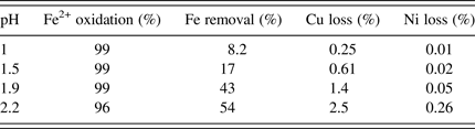
The composition of influent used in the Case Two study is given in Table III. The results of iron oxidation and removal for the two-stage CSTR system are presented in Table IV along with the percentages of copper and nickel loss to the solid precipitates. These results indicate that Fe3+ was effectively oxidized for all influent pH values. The percentage of iron removal increased with increasing influent pH, and reached 54% for influent pH 2.2. The percentage of valuable metals (Cu and Ni) lost also increased with increasing influent pH (Table IV).
Table III. Elemental concentrations of influent used in the Case Two study (Kaksonen et al., Reference Kaksonen, Morris, Suzy, Li, Wylie, Usher, Ginige, Cheng, Hilario and du Plessis2014a).
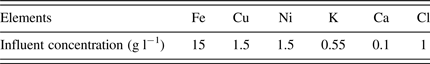
Table IV. The percentage of iron oxidation and valuable metals losses from the two-stage CSTR system (Kaksonen et al., Reference Kaksonen, Morris, Suzy, Li, Usher, McDonald, Hilario, Hosken, Jackson and du Plessis2014a).

XRD analysis of the precipitates collected from the CSTR1 and 2 indicates that jarosite is the only crystalline mineral present (Figure 5). However, the presence of schwertmannite or other poorly crystalline iron precipitates (e.g. ferrihydrite) cannot be discounted as these may not be readily detected by the XRD when highly crystalline phases are present (i.e. jarosite in this study). In sulphate-containing systems, the formation of schwertmannite is thermodynamically favoured in the pH range of 2–8 (Majzlan et al., Reference Majzlan, Navrotsky and Schwertmann2004). A more recent study (Brand et al., Reference Brand, Scarlett, Grey, Knott and Kirby2013) indicated the possible presence of amorphous material as a precursor to the formation of crystalline natrojarosite. The addition of an internal standard, fluorite, allows the amorphous content of the jarosite precipitate to be calculated from the QXRD analysis by difference. For instance, if the QXRD analysis indicates 97% jarosite with 3% “unaccounted for material”, the latter is considered to represent the amorphous content. The purity or the crystallinity of the jarosite is said to be 97%. Using chemical analysis data, the monovalent cation occupancy of the jarosite can also be derived from the QXRD analysis, assuming that all the K, Na, and N (as NH4+) present in the sample occupy the same site as H3O+ in the jarosite structure. The crystallinity and K occupancy of the jarosite formed in the two stages at different pH are presented in Figures 6(a) and 6(b).
Figure 5. (Color online) XRD of the precipitates collected from CSTR1 and 2 operated at room temperature and influent pH of 1.5; the precipitates were mixed with 10% (w/w) fluorite.
Figure 6. (Color online) Crystallinity of precipitates in CSTR1 and 2 (a) K occupancy of jarosite in CSTR1 and 2 (b) obtained at room temperature.
The stability of jarosite analogues is expected to follow the order K+ > Na+ > H3O+ > NH4+ from estimates of both heat of formation (Drouet and Navrotsky, Reference Drouet and Navrotsky2003) and Gibbs free energy (Gaboreau and Vieillard, Reference Gaboreau and Vieillard2004). In the present study, given the presence of sufficient potassium, it was expected that K occupancy, which is the molar value of M as K in jarosite formula of MFe3(SO4)2(OH)6 (where M = Na, K, and H3O), would be significant.
The results indicated that the precipitates from CSTR2 contained less impurities compared with those from CSTR1, except at influent pH 2.2 [Figure 6(a)]. The crystallinity of the precipitates increased with increasing influent pH in both CSTRs, except at pH 2.2. The crystallinity of the precipitate in CSTR2 with influent pH 2.2 actually reduced to ~75%. The reason for this anomaly is unclear. Higher amounts of K+ were incorporated into jarosite from CSTR1 compared with CSTR2 [Figure 6(b)]. The amount of K+ incorporation reduced with increasing influent pH in both CSTRs. However, the change was relatively small in CSTR1 (~15% reduced from pH 1.0 to 2.2), but larger in CSTR2 (~70% reduction from pH 1.0 to 2.2) [Figure 6(b)]. Dutrizac and Jambor (Reference Dutrizac, Jambor, Alpers, Jambor and Nordstrom2000) indicated that the level of Na+ incorporated into jarosite was not affected by the change of pH in the range of 0–2, but the amount of jarosite formation reduced from ~90 to 0% when the pH decreased from 2 to 0.5. This explains the near-steady level of K+ in jarosite from CSTR1. With lower concentrations of K+ in solution going into CSTR2 and with increasing pH, less K+ was expected to be incorporated into jarosite from CSTR2.
IV. CONCLUSION
In the Case One study, the hydrothermal conversions of pyrrhotite and pentlandite were demonstrated and quantified using Rietveld-based QXRD analysis and the findings agreed well with previous observations. In addition, a nickel sulphide mineral with cubic structure similar to vaesite and bravoite was identified. Although the leaching of the nickel concentrate produced a significant amount of basic ferric sulphate, the co-processing of nickel laterite and sulphide was shown to generate residues that are more environmentally acceptable. Rietveld-based QXRD analysis can be applied to investigate reaction pathways and specifically the oxidation of sulphide minerals. This may have implications for the geological formation of secondary minerals from primary sulphides. In the Case Two study, QXRD analysis was applied to monitor the solid formation in the bio-processing of iron-containing leach liquors, characterize the mineralogy and crystallinity of the precipitates, and to derive the cation occupancy of the formed jarosites using chemical data.
ACKNOWLEDGEMENTS
The authors acknowledge financial support of CSIRO Mineral Resources Flagship, Vale, Poseidon Nickel, and the Goldfields Esperance Development Council. The authors also thank Barry Halstead (CSIRO Clayton) for collecting the XRD data, and staff in Analytical group in CSIRO Waterford site for chemical analysis of samples discussed in this study.