I. INTRODUCTION
Cellulose, (C6H10O5)n, is a linear macromolecule comprised of β-d-glucose units (Saito, Reference Saito, Kennedy, Phillips and Williams1989). Cellulose materials are typically semicrystalline (comprised of crystalline and amorphous components), with several crystalline polymorphs known to exist (Fawcett et al., Reference Fawcett, Crowder, Kabekkodu, Needham, Kaduk, Blanton, Petkov, Bucher and Shpanchenko2013). The generation of cellulose II from native cellulose (cellulose I) can be accomplished using the methods of regeneration (dissolving in a derivative-forming solvent) or mercerization (swelling in concentrated sodium hydroxide) (Kolpak et al., Reference Kolpak, Weih and Blackwell1978).
A Debye–Scherrer film exhibiting a shriveled and distorted appearance was submitted for analysis. It was determined by X-ray diffraction (XRD) that the polymer film base was cellulose II, an indication that the original film base was cellulose triacetate. Cellulose triacetate can deteriorate with age, characterized by the emission of acetic acid (vinegar syndrome), resulting in a film that becomes brittle, and in extreme cases turns to powder (National Archives, 2000). During this study, cellulose triacetate samples were exposed to various chemical treatments, and some of the resulting samples were identified by XRD as crystalline cellulose II.
The atomic coordinates for cellulose II contained in Powder Diffraction File entry 00-056-1717 (ICDD, Reference Kabekkodu2012) were derived by a density functional geometry optimization (Kaduk and Langan, Reference Kaduk and Langan2003) of the structure using CASTEP (Milman et al., Reference Milman, Winkler, White, Pickard, Payne, Akhmatskaya and Nobes2000) and the fixed experimental unit-cell parameters from Langan et al. (Reference Langan, Nishiyama and Chanzy2001). The preparation of bulk samples of cellulose II mentioned above has permitted the determination of more precise unit-cell parameters, and a new DFT geometry optimization, resulting in an improved cellulose II pattern for the Powder Diffraction File.
II. EXPERIMENTAL
A. Sample preparation
Preparation of cellulose II is based on experiments carried out at Eastman Kodak Company, while studying deacetylation of cellulose acetate-based photographic films. The procedure has been modified so that it can be carried out in a laboratory setting.
Into a glass flask was added 180-g deionized H2O, 180-g aqueous ammonia (NH3 assay 29.8%, J.T Baker), and 45-g cellulose acetate powder (Eastman Kodak). Using a magnetic stirrer/hot plate, the mixture was continuously stirred at room temperature for 45 h, then over a period of 1.5 h while heating to 50 °C, and at 50 °C for 3 h. The flask was removed from the hot plate, allowed to cool to 35 °C, stirred for 1 min then filtered (Millipore Type LS) using a vacuum filtration apparatus. The collected solids were washed with 250 ml 40% (v/v) acetic acid/H2O, followed by two washes with 200-ml glacial acetic acid, and four washes with 250-ml methanol. All solids were transferred to a glass dish and dried at 40 °C for 14 h. An aliquot of the dried powder was analyzed by XRD and identified as cellulose II. A scanning electron microscope micrograph of this cellulose II sample is shown in Figure 1.

Figure 1. Scanning electron microscope micrograph of cellulose II powder sample.
B. X-ray diffraction
A portion of the cellulose II sample was blended with ~5 wt% NIST SRM 640b silicon internal standard, and packed into a 50-μm deep quartz zero-background cell. The X-ray powder pattern was measured (5–70°2θ, 0.020 2144° steps, 2 s per step, 0.6-mm divergence slit, 2.5° Soller slits, 1-mm scatter screen height) on a Bruker D2 Phaser diffractometer using only the central 96/192 channels of the LynxEye position-sensitive detector. The resulting XRD pattern was processed by the Rietveld method using GSAS (Larson and Von Dreele, Reference Larson and Von Dreele2004) and the fixed structural model from PDF entry 00-056-1717.
The previous CASTEP (Milman et al., Reference Milman, Winkler, White, Pickard, Payne, Akhmatskaya and Nobes2000) geometry optimization for cellulose II, used to generate the coordinates in PDF entry 00-056-1717, was carried out using the CGA-PW91 functional, with a plane wave energy cut-off of 340.0 eV (fine basis set), and a k-point spacing of 0.08 Å−1 (two-point sampling of the Brillouin zone of the primitive cell). The unit-cell parameters were fixed at the experimental values (space group P1121) a = 8.10(3), b = 9.03(3), c = 10.31(5) Å, and γ = 117.10(5)°. The compound was treated as a metal, and the default number of orbitals was increased by 10% to include some empty orbitals in the calculation. Plausible initial positions for the hydroxyl hydrogen atoms were derived by analysis of the O···O distance of potential hydrogen bonds. The input hydrogen positions were averages of these, in an attempt to avoid local minima.
The Rietveld refinement included phase fractions for cellulose and silicon, as well as cellulose unit-cell parameters. The cellulose profile X, silicon profile Y, and a common specimen displacement coefficient were refined. The background was modeled using a three-term shifted Chebyshev function; the initial coefficients were based on those obtained from a refinement using data collected at the same conditions on a glucose sample, but the coefficients were refined. A three-term diffuse scattering function was included, with fixed characteristic distances of 1.57(5), 3.15(5), and 8.84(5) Å.
Using the (fixed) refined unit-cell parameters: a = 8.076(13), b = 9.144(10), c = 10.386(20) Å, and γ = 117.00(8)°, a new geometry optimization was carried out using CRYSTAL09 (Dovesi et al., Reference Dovesi, Orlando, Civalleri, Roetti, Saunders and Zicovich-Wilson2005). The basis sets for the H, C, and O atoms were those of Gatti et al. (Reference Gatti, Saunders and Roetti1994). A density functional calculation using eight k-points and the B3LYP functional was carried out.
III. RESULTS AND DISCUSSION
An acceptable Rietveld refinement (Figure 2) was obtained: R wp = 0.0589 and χ 2 = 4.704. The transparency of the specimen, even in a thin layer in a zero-background cell, resulted in Si profiles that were hard to describe using GSAS profile function number 2. The refined cellulose profile X coefficient of 202(3) corresponds to an average crystallite size of 39(1) Å. The diffuse scattering function contribution to the pattern is minor. Removing the diffuse scattering function from the refinement yielded a residual ~18°2θ. Manual integration of this residual suggested the presence of ~15% amorphous component. Despite the appearance of the pattern, cellulose II is highly crystalline.
Figure 2. Observed, calculated, and difference patterns from the Rietveld refinement used to determine the lattice parameters of cellulose II. The red crosses represent the observed data points, the green line through them the calculated pattern. The magenta difference curve is plotted at the same vertical scale as the other patterns.
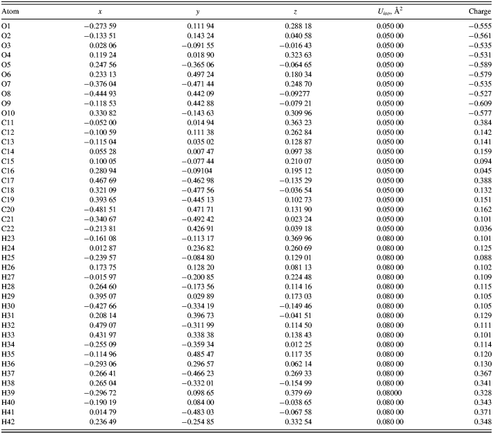
The DFT-optimized atom coordinates are reported in Table I. A powder pattern calculated using these coordinates has been submitted to the ICDD for inclusion in future versions of the Powder Diffraction File. The initial and final structures are very similar (Figure 3). The root-mean-square displacement of the non-hydrogen atoms in the C17–C22/O5–O9 monomer at the center of the unit cell is 0.067 Å. The chain–chain differences are larger. The energy difference between the two structures is only 0.12 kcal mole−1 of monomer.
Figure 3. Overlap between the initial (from PDF entry 00-056-1717) and final structural models for cellulose II.
Table I. DFT optimized atom coordinates for cellulose II, calculated by CRYSTAL09. Space group P1121, a = 8.076(13), b = 9.144(10), c = 10.386(20) Å, γ = 117.00(8)°, and V = 683.5(18) Å3.
As expected, a Mercury/Mogul Geometry Check of the optimized structure (Figure 4) reveals very few geometrical features outside the normal ranges. Only the O3–C11 bond distance of 1.403 Å (1.25(6)) and the O3–C14–C13, C17–C18–C19, O6–C19–C18, and O8–C21–C20 angles of 112.52 (108.0(21)), 113.75 (110.0(19)), 105.09 (110.3(22)), and 106.96° (110.2(16)) fall outside the default Mogul ranges within Mercury. A search directly in Mogul 1.4 (which has larger default tolerances) indicates that the O3–C11 bond is normal [1.395(19) Å], and confirms that the listed angles lie on the tails of the normal distributions in glucose polymers.
Figure 4. The asymmetric unit of cellulose II, with atom numbering.
The most interesting feature of the structure is the hydrogen bonds (Table II and Figure 5). A positive Mulliken overlap population serves to distinguish real hydrogen bonds from potential (by geometry) hydrogen bonding interactions. The hydrogen bonds involving the methylene side-chain hydroxyl groups O9 and O10 are stronger than the others, but none of the hydrogen bonds are exceptionally strong. Using the correlation that the energy of a hydrogen bond (in kcal/mole) equals 147.1 × overlap0.53 (Kaduk, Reference Kaduk2002), these hydrogen bonds contribute 83.5 kcal/mole/monomer to lattice energy.
Figure 5. The hydrogen bonds in cellulose II.
Table II. Hydrogen bonds in cellulose II.

The charges on the ether oxygen atoms O3, O4, O7, and O8 are slightly less negative than those on the hydroxyl oxygens. As expected, the hydroxyl hydrogens are more positive than those bonded to carbon. All of the carbon atoms bear a slight positive charge. Any correlation between the charges on the hydrogens involved in the hydrogen bonds and the overlap population is very weak.
There are two crystallographically independent chains in the cellulose II structure (Figure 6), both along the c-axis. The planes of the glucose rings lie approximately in the ac-plane. The hydrogen bonds involving H38, H39, H41, and H42 link chains, while H37 and H40 participate in intrachain hydrogen bonds. H40 forms bifurcated hydrogen bonds.
Figure 6. The crystal structure of cellulose II, viewed down the c-axis in P1121 (down the chains).
The BFDH morphology (Bravais, Reference Bravais1866; Friedel, Reference Friedel1907; Donnay and Harker, Reference Donnay and Harker1937; Figure 7) calculated from the crystal structure using Mercury (Sykes et al., Reference Sykes, McCabe, Allen, Battle, Bruno and Wood2011), though slightly elongated along the chain (c) axis, is not especially anisotropic. This result suggests that fibers of cellulose II consist of smaller domains. The fibers typically observed in native celluloses (Nishiyama, Reference Nishiyama2009) are apparently the result of the formation processes rather than the crystal structures themselves.
Figure 7. Bravais–Friedel–Donnay–Harker calculated morphology of cellulose II.
Powder patterns calculated from this structure model reproduce the observed pattern well (Figure 8). The major deviation is ~34°2θ, a region that is also the poorest in calculated patterns of cellulose I α and I β (Fawcett et al., Reference Fawcett, Crowder, Kabekkodu, Needham, Kaduk, Blanton, Petkov, Bucher and Shpanchenko2013). A pattern based on the one calculated with narrow peaks has been submitted to ICDD for inclusion in future releases of the Powder Diffraction File.
Figure 8. Observed and calculated powder patterns of cellulose II.
ACKNOWLEDGMENTS
The authors thank Dr Q. Johnson, Materials Data Inc., for providing the distorted Debye–Scherrer film that initiated the study for chemical deacetylation methods for cellulose II generation.