


Introduction
During past decades, compressed plasma flow (CPF) was intensively studied as a typical source of intense thermal loads. Due to its thermal effect on the material surface, cracks, melting, ripples, droplets, evaporation, sublimation, or ablation will be formed. Similar burst of particles exists in the edge localized modes (ELMs) of the International Thermonuclear Experimental Reactor (ITER) as well, which is attributed to the turbulent transport process and plasma instability localized in the Tokamak edge region. Therefore, CPF is widely applied in material surface modification (Astashynski et al., Reference Astashynski, Ananin, Askerko, Kostyukevich, Kuzmitski, Uglov, Anishchik, Astashynski, Kvasov and Danilyuk2004) and environment simulation for ELMs (Garkusha et al., Reference Garkusha, Malykhin, Makhlai, Pugachev, Bazdyrieva and Aksenov2014).
As one of the key ITER plasma-materials interaction issues (Federici et al., Reference Federici, Andrew, Barabaschi, Brooks, Doerner, Geier, Herrmann, Janeschitz, Krieger, Kukushkin, Loarte, Neu, Saibene, Shimada, Strohmayer and Sugihara2003), material surface behavior under plasma thermal loads during type I ELMs was focused on plenty of works (Uglov et al. Reference Uglov, Anishchik, Astashynski, Astashynski, Ananin, Askerko, Kostyukevich, Kuz'mitski, Kvasov and Danilyuk2002, Reference Uglov, Remnev, Kuleshov, Astashinski and Saltymakov2010; Astashynski et al. Reference Astashynski, Ananin, Emelyanenko, Kostyukevich, Kuzmitzky, Zhvavy and Uglov2006; Dojčinović et al. Reference Dojčinović, Kuraica and Purić2010). Among these works, a quasi-stationary plasma gun of magnetoplasma compressor (MPC) was selected as the source of CPF. Filled with hydrogen at 100–5000 Pa, MPC working with initial capacitor banks voltage at 3–4 kV, inter-electrode voltage at 1.25 kV can generate CPF with current 80–100 kA, effective discharge duration 70 µs, average plasma density 5 × 1016 cm−3, plasma flow velocity up to 120 km/s (Dojčinović et al., Reference Dojčinović, Kuraica, Obradovć, Cvetanović and Purić2007a; Dojčinović et al., Reference Dojčinović, Kuraica and Purić2010).
After the action of CPF on (100) single-crystal silicon, two kinds of fracture are observed on the surface. One is surface-latticed linear fracture and the other is interlaminar planar fracture along {100} planes parallel to the surface (Dojčinović et al., Reference Dojčinović, Kuraica and Purić2010). As shown in Figure 1, the latter fracture drives the occurrence of exfoliation, thus the surface fragment is removed and subsurface is revealed after exfoliation. As an indispensable part of the surface erosion, ablation and target mass losses, it is of great importance to study the formation mechanism of the interlaminar planar fracture for the investigation of plasma interaction with fusion reactor first wall materials.

Fig. 1. SEM micrograph of cross-section of silicon (100) sample treated by CPF (Dojčinović et al., Reference Dojčinović, Kuraica and Purić2010).
To explain this, Griffith criterion has been used qualitatively (Dojčinović et al., Reference Dojčinović, Kuraica and Purić2010), and the shock-wave theory was applied as well (Uglov et al., Reference Uglov, Remnev, Kuleshov, Astashinski and Saltymakov2010). Nevertheless, shock wave will not always result in fracture, and the role CPF played as a surface thermal load in the initiation of interlaminar fracture remains uncertain. For example, the reason why fracture features were only observed in the central part of the target (Dojčinović et al., Reference Dojčinović, Kuraica and Puric2007b), and the reason why exfoliated layer was no more than 10 µm are still to be shed light on.
Similarly, interlamniar fractures have also been discovered on the surface of silicon (Kovivchak et al., Reference Kovivchak, Panova, Krivozubov, Davletkil'deev and Knyazev2012; Shen et al., Reference Shen, Yu, Zhang, Zhong, Zhang, Qu, Yan, Zhang, Zhang and Le2015) and tungsten (Remnev et al., Reference Remnev, Uglov, Shymanski, Pavlova and Kuleshovb2014) irradiated by another impact thermal load source intense pulsed ion beam (IPIB) (Zhao et al., Reference Zhao, Remnev, Yan, Opekounov, Le, Matvienko, Han, Xue and Wang2000). Even though different crystallographic orientation samples were utilized, interlaminar planar fracture parallel to the surface can always be observed. It was concluded that the non-uniformity of stress distribution between the bulk and outmost layer actuates the interlaminar fracture parallel to the surface and finally leads to exfoliation. The J integral model combined with linear elastic mechanics has been applied to study the material behavior and judge the possibility of interlaminar planar fracture initiation (Shen et al., Reference Shen, Shahid, Yu, Zhang, Zhong, Cui, Liang, Yu, Huang, Yan, Zhang, Zhang and Le2017). It provides a good reference for the study of CPF, but considering the significantly different loading rates, energy deposition depths and energy density, it will be beneficial to develop a model specifically for CPF.
Taking (100) single-crystal silicon used in the experiment work (Dojčinović et al., Reference Dojčinović, Kuraica and Purić2010) as an example, the purpose of this work is to better understand the formation mechanism of exfoliation driven by {100} interlaminar planar fracture under the action of CPF and reveal the answers for the above-mentioned problems. In this case, a quantitative relationship between CPF parameters and interlaminar fracture features should be constructed as well. It will eventually enable one to avoid these undesirable microstructures by adjusting CPF parameters, and in engineering applications, it can also be beneficial for the evaluation of surface behavior under different pulsed thermal loads.
Finite element method simulation
Before the model establishment, it is of great necessity to review the exfoliation process. At the very beginning, CPF action can lead to interlaminar planar fracture initiation along {100} planes parallel to the surface, and separate the outmost layer from the substrate surface. In this stage, even though {111} and {110} planes are usually more preferred at regular thermal stress loading (Danilewsky et al., Reference Danilewsky, Wittge, Kiefl, Allen, McNally, Garagorri, Elizalde, Baumbach and Tanner2013), the CPF energy deposition with an energy density up to 1.0 MJ/m2 during tens of microseconds is so strong and fast that the crystal directions with 0.5 J/m2 maximum surface energy difference (Tanaka et al., Reference Tanaka, Higashida, Nakashima, Takagi and Fujiwara2006) are too weak to make difference in this non-equilibrium state process. After crack growth, the surface energy is weakened rapidly and the binding energy difference becomes significant; thus, the cleavage fracture along {111} planes toward the surface occurs as demonstrated in the experiment (Dojčinović et al., Reference Dojčinović, Kuraica and Purić2010). In this way, the exfoliated area is limited and bounded by cleavage fractures.
Based on the above process, it is important to firstly define the thermal load applied onto the study object for fracture mechanics analysis. Afterwards, the main idea is to get the stress distribution around the notch, crack tip or some other crack sources within a specific area, and then use an appropriate criterion to evaluate the possibility of crack growth. Therefore, the processes of this work can be briefly illustrated in Figure 2.
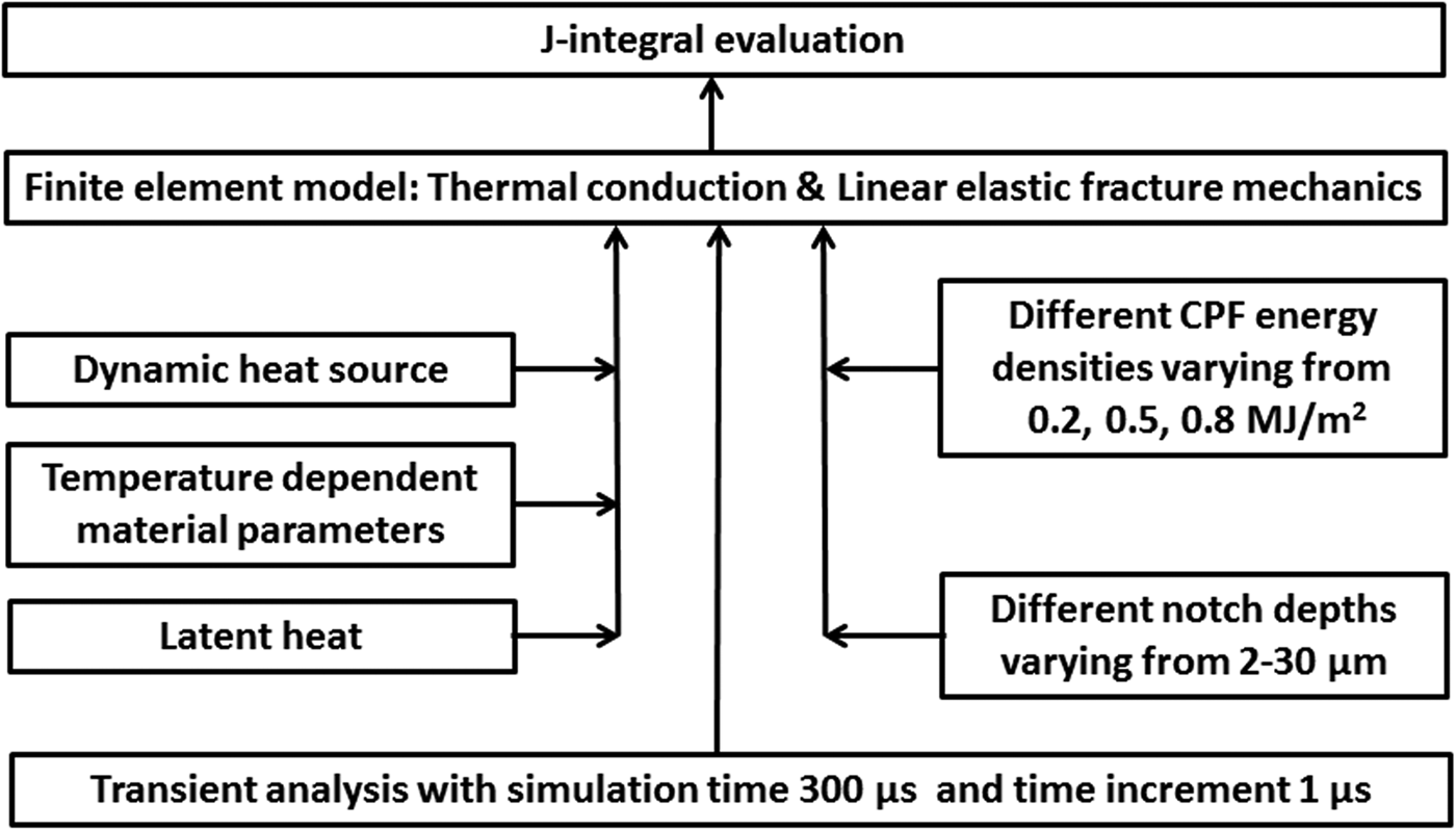
Fig. 2. The schematic diagram of the analytical model.
According to the dimension of the silicon target used in (Dojčinović et al., Reference Dojčinović, Kuraica and Purić2010), a 10 µm × 1 mm rectangular cross-section of single-crystal silicon was studied as shown in Figure 3, where 10 µm stands for an area large enough for the study of micro scale single crack, and 1 mm is the total target depth. A micro scale notch with 1–4 µm lengths, 0.2 µm height, and 2–26 µm depths on the upper left corner was preset in the square. The notch stands for the potential crack source, which probably evolved from the original defect through defect generation, migration, and nucleation (Masters & Gorey Reference Masters and Gorey1978; Gao et al., Reference Gao, Qin, Dong and Li2014). According to (Bailey & Sethna Reference Bailey and Sethna2003), the crack opening angle can significantly affect the value of the critical stress intensity factor. For this reason, a U-type notch was used rather than a V-type one.

Fig. 3. Meshed two-dimensional cross-section of single-crystal silicon irradiated by CPF with a crack tip surrounded by a J integral path.
In this work, as thermal stress induced by CPF is the applied load, the thermal conduction process should be taken into consideration. Thus, Fourier heat conduction equation was adopted as the governing equation:
 $${\rm \rho} C_{\rm v}\displaystyle{{\partial T} \over {\partial t}} = {\rm \lambda} \nabla ^2T + P$$
where ρ, C V, and λ are the mass density, specific heat, and thermal conductivity of the target, respectively, and all of them are temperature-dependent parameters. Worth to mention, based on our evaluation, the melt layer depth is within half micrometer, which is also demonstrated in (Dojčinović et al., Reference Dojčinović, Kuraica and Purić2010). Therefore, the phase change process was not taken into account in this work.
Based on our previous work (Yu et al., Reference Yu, Shen, Qu, Liu, Zhong, Zhang, Zhang, Yan, Zhang, Zhang and Le2015), the external heat source term P(x,y,t) induced by CPF can be defined as:
 $$P(x,y,t) = U(x) \cdot d(y) \cdot g\left( t \right)$$
Here P(x, y, t) is the power density distribution on the target induced by IPIB. U(x) is the cross-sectional energy distribution function. As the studied sample size in this work is 10 µm much smaller than the beam spot (around one centimeter), so U(x) can be approximately replaced by a constant; d(y) shown in Figure 4a is the dimensionless depth-normalized energy loss distribution over the depth y, which can be readily obtained by simulating the penetration of 1.25 keV protons efficiently accelerated by inter-electrode voltage with Monte Carlo software SRIM (Ziegler et al., Reference Ziegler, Ziegler and Biersack2010). When considering the power density in material, it is assumed that the deposited energy from CPF is mainly contributed by positive ions when taking the mass difference and shot range difference between ions and electrons into consideration. Multiple trials of simulation have been carried out with various shapes of d(y), like rectangular or triangular distribution within a depth range of 20–500 nm, which showed that no significant difference was generated as long as the energy density value was fixed; g(t) shown in Figure 4b is the dimensionless time-normalized power density evolution function, which can be calculated with the current waveform obtained in (Dojčinović et al., Reference Dojčinović, Kuraica, Obradovć, Cvetanović and Purić2007a).

Fig. 4. (a) Depth-normalized energy loss per unit length in material surface for ions in CPF; (b) time-normalized energy distribution of CPF during the first 70 µs.
For initial condition, we took:
 $$T(x,y,0) = T_0$$
here T 0 is room temperature 298 K.
For boundary condition, Stefan–Bolzmann boundary condition was taken for the upper surface to evaluate the energy loss by infrared radiation:
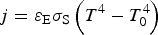 $$j = {\rm \varepsilon} _{\rm E}{\rm \sigma} _{\rm S}\left( {T^4 - T_0^4} \right)$$
where j is the surface-to-ambient radiative heat flux, εE is the emissivity, which here takes 0.5 for silicon, and σS is the Stefan–Boltzmann constant; adiabatic boundary was adopted for the rest boundaries. In addition, as the air pressure in the vacuum chamber is quite low, convective thermal transfer is not taken into consideration, either.
Up to now, the temperature evolution over the studying area can already be obtained. In order to analyze the stress and strain configuration after CPF action, elastic linear mechanics is considered for silicon as well.
As an expression of Newton's second law, the material's motion equation was adopted to describe the thermodynamic process:
 $$\nabla \cdot {\rm \sigma} = {\rm \rho} \displaystyle{{\partial ^2{\bf u}} \over {\partial t^2}}$$
where σ, ρ, u stand for Cauchy stress tensor, mass density, and displacement vector, respectively.
The relationship between strain and displacement is defined with infinitesimal strain theory:
 $${\rm \varepsilon} = \displaystyle{1 \over 2}\left[ {\nabla {\bf u} + {(\nabla {\bf u})}^T} \right]$$
where ε is the infinitesimal strain tensor, while  $(\nabla {\bf u})^T$ is a transpose of
  $\nabla {\bf u}$.
The general equation for Hooke's law to describe the elastic material behavior:
 $${\rm \sigma} = {\bf D}{\rm \varepsilon} _{{\rm el}} = {\bf D}\left( {{\rm \varepsilon} - {\rm \varepsilon} _{{\rm th}}} \right)$$
where D is the elasticity matrix, εel and εth are the elastic strain and thermal strain, respectively.
Zero displacement boundary conditions are set for all the boundaries except the upper surface, which is unrestricted in this model.
To combine the thermal conduction model and linear elastic mechanics model, temperature distribution was connected to thermal strain with:
 $${\rm \varepsilon} _{{\rm th}} = {\rm \alpha} (T - T_0)$$
where α is the temperature-dependent coefficient of thermal expansion. The above equations were solved by Comsol Multiphysics, a finite element method (FEM) tool. Time step for the solution is 1 µs and the whole study duration is 300 µs.
J Integral analysis
In scientific research, there was a strong desire for natural phenomena at a fundamental level. To explain fracture physically, the famous Griffith theory (Griffith Reference Griffith1921) treats critical fracture as an equilibrium state when the strain energy loss can be equated to the newly generated surface energy due to the crack growth of an infinitesimal length. Proposed by Eshelby (Eshelby Reference Eshelby1999) and Rice (Rice Reference Rice1968), J integral is a path-independent parameter in a line integral form, which has been widely used due to its attractive features.
In this work, since now the dynamic evolution of the stress and strain field around the crack tip can already be calculated quantitatively, a valid method has to be employed to predict the crack growth. As an effective bridge to connect the strain field around the crack tip to the strain energy release rate, J integral becomes a promising candidate. To be specific, J integral is a two-dimensional line integral along Γ, a counterclockwise contour surrounding the crack tip shown in Figure 3. It is defined as:
 $$J = \mathop \int \limits_{\rm \Gamma} ^{} {\rm (}Wdy - {\bf T}_i\displaystyle{{\partial u_i} \over {\partial x}}ds{\rm )}$$
where W is the strain energy per unit volume subjected to arbitrary stresses:
 $$W = \displaystyle{1 \over 2}({\rm \sigma} _x \cdot {\rm \varepsilon} _x + {\rm \sigma} _y \cdot {\rm \varepsilon} _y + 2 \cdot {\rm \sigma} _{xy} \cdot {\rm \varepsilon} _{xy})$$
And T is the traction vector defined according to the outward normal unit vector n along Γ:
 $${\bf T}_i = {\rm \sigma} _{ij} \cdot {\bf n}_i$$
With the J integral parameter, K I factor which can be obtained if treating silicon as linear elastic:
 $$K_{\rm I} = \sqrt {\displaystyle{{J \cdot E} \over {1 - {\rm \nu} ^2}}} $$
where E is the Young's modulus and ν is the Poisson's ratio. K factor can be applied as a criterion if comparing it with the critical stress intensity factor K IC for different materials. In other words, in a dynamic loading case, one can obtain the critical J parameter J C for a specific material, and compare the dynamic J parameter with J C as a criterion to judge if the crack can initiate or not. All the parameters mentioned above correspond to single-crystal silicon (100). Worth to mention, different crystallographic directions of silicon wafer have different critical stress intensities (Johansson et al., Reference Johansson, Ericson and Schweitz1989). Critical stress intensity for silicon (100) in our work was utilized to obtain critical J C in accordance with the actual wafer used in (Dojčinović et al., Reference Dojčinović, Kuraica and Purić2010).
FEM simulation results
As reported in (Dojčinović et al., Reference Dojčinović, Kuraica and Purić2010) that two kinds of fractures are formed on single-crystal silicon after CPF action: one is the waffle-like surface fracture and the other is the interlaminar fracture, which finally leads to exfoliation. According to the previous work (Kovivchak et al., Reference Kovivchak, Panova, Krivozubov, Davletkil'deev and Knyazev2012), the former fracture develops along the cleavage plane due to fast quenching process. Its formation mechanism can be comparable to that of mud-crack (Shorlin et al., Reference Shorlin, Bruyn, Graham and Morris2000). Due to the fast temperature rise induced by CPF within the first hundred μs in time and several μm in depth, the material surface was rapidly expanded (Astashynski et al., Reference Astashynski, Ananin, Emelyanenko, Kostyukevich, Kuzmitzky, Zhvavy and Uglov2006). Closely after that, the surface temperature decreases sharply and inevitably leads to shrinkage. In such a rapid stress load, the material cannot behave with only elastic deformation. Therefore, fracture is launched to release the energy, and naturally it develops along the cleavage plane where the minimum binding energy exists. Thus, the waffle-like surface fracture is achieved.
When it comes to the interlaminar fracture, the waffle-like fracture has made the silicon surface into separated blocks, and the interlaminar fracture is driven to initiate in mode I by thermal loading. In this way, the exfoliation region is generated with a depth around 10 µm. The exfoliated shape is restricted into square for silicon (100) or rhombus with 60 and 120° corners for silicon (111). It can be readily calculated by SRIM that the ion range for the protons in CPF in this case is much smaller than 1 µm. So it can be deduced that the interlaminar crack develops in deeper depth than ion range. Because of the pressure gradient induced by shock-wave effect, the modified layer of the surface depth is much larger than the CPF ion range. In this case, to figure out the exfoliation mechanism, and thus optimize the CPF parameter in future industrial application, it becomes important to develop a model which enables us to evaluate the modified layer status and forecast the crack behavior after CPF action.
By simulation, the typical distributions of temperature and stress are illustrated in Figure 5. The existence of the preset notch breaks the symmetry of distribution, and makes it non-uniform at the same depth. A large gradient of temperature and stress in the surface layer can still easily be figured out. As indicated in (Uglov et al., Reference Uglov, Remnev, Kuleshov, Astashinski and Saltymakov2010), GPa level shock wave will be generated under CPF action. The maximum value in stress distribution in Figure 5b can also arrive at this level. But we can see the maximum is located at geometric corners where stress is concentrated. From the distribution, one can hardly figure out whether the fracture can initiate from the notch or not. In this case, numerical evaluation will be more convincing than qualitative analysis in the fracture initiation issue. That is why J integral should be applied next.

Fig. 5. The distribution of (a) temperature and (b) stress field at 15 µs induced by CPF with cross-sectional energy density of 0.5 MJ/m2 in single-crystal silicon.
Model validity
One big issue of the model applicability for CPF thermal load is to verify its validity. The first concern is that CPF action is a dynamic thermal loading process, and the path-independent J integral may not work. As shown in Figure 6a, the trial was carried out with four different paths around the crack tip. The paths 1–4 are in square shape with side lengths of 0.5, 1.0, 1.5, and 2.0 µm, respectively. One can see no big difference exists in the evaluation results between these paths. It can conclude that the choice of integral path will not bring uncertainty to the result.

Fig. 6. J integral value for 0.2 MJ/m2 CPF and 6 µm depth notch at different (a) paths and (b) notch lengths.
Another concern is that whether the choice of the dimension of the notch will affect the evaluation result. The defect size in single-crystal silicon varies from several nm to hundreds of nm. As J integral can slightly increase with notch height, the notch height is fixed in this work at 0.2 µm according to the maximum defect size reported in (Vanhellemont et al., Reference Vanhellemont, Senkader, Kissinger, Higgs, Trauwaert, Gräf, Lambert and Wagner1997). After CPF action, the defects may generate, migrate, and nucleate as has been stated above. Especially under such powerful shock wave, due to the defect connection mechanism (Gnyusov et al., Reference Gnyusov, Rotshtein, Mayer, Rostov, Gunin, Khishchenko and Levashov2016), the crack source may become longer than original defect size. Figure 6b presents different results with various notch lengths, from which one can conclude that the choice of notch length will make limited difference in the evaluation.
Evaluation results and discussion
To analyze the stress distribution around the crack tip after CPF, thermal conduction model and linear elastic mechanics model are combined. After obtaining the temperature and stress distribution, J integral now should be applied to estimate the energy release rate around the crack tip. The J parameter can be obtained as a criterion of crack growth by comparing with critical value J C. Worth to mention, the critical fracture toughness K IC, which can be readily transformed to J C for micro scale single-crystal silicon has been intensively studied with experiment (Fitzgerald et al., Reference Fitzgerald, Dauskardt and Kenny2000; Sundararajan & Bhushan Reference Sundararajan and Bhushan2002) or molecular dynamic simulation (Bailey & Sethna Reference Bailey and Sethna2003). In this work, a fixed value 5.1 N/m specifically for Si (100) (Johansson et al., Reference Johansson, Ericson and Schweitz1989) is taken as shown in Figure 7.

Fig. 7. The evolution of J integral parameter during the first 300 µs for mode I interlaminar fracture generated at different depths under the action of CPF with energy density at: (a) 0.2; (b) 0.5; (c) 0.8 MJ/m2.
When considering the effect of crack depth, it is demonstrated in Figure 7 that with a specific energy density and larger depth, J value decreases and the peak value comes later. The latter represents the peak of shock wave, and it is easy to understand that shock wave attenuates during propagating and deeper crack interacts with shock wave later.
When it now comes to the energy density, the situation varies. For low-energy density in Figure 7a, the J integral for the surface layer is much smaller than the critical value, which indicates that no interlaminar fracture can initiate at this case. When energy density comes to 0.5 MJ/m2 as shown in Figure 7b, it seems possible for interlaminar fracture to develop within a very shallow layer. However, one cannot easily conclude that exfoliation must occur within these several μm. That is because exfoliation needs a suitable crack source, whose existence depends on the defect distribution status. For CPF with 0.8 MJ/m2 energy density as shown in Figure 7c, the depth range for interlaminar fracture development is within 22 µm. In this case, considering the defect density in single-crystal silicon, there will probably be suitable crack source, which can finally lead to interlaminar fracture.
Based on the above results, it becomes easy to explain the experimental result that the exfoliation only occurs in the central part of the target (Dojčinović et al., Reference Dojčinović, Kuraica and Puric2007b; Dojčinović et al., Reference Dojčinović, Kuraica and Purić2010). It is claimed that with conducted calorimetric measurement, the power density of typical CPF ranges from 0.5 × 10⁵ to 3 × 10⁵ W/cm2 in 120 µs discharge duration depending on the sample location (Uglov et al., Reference Uglov, Anishchik, Astashynski, Astashynski, Ananin, Askerko, Kostyukevich, Kuz'mitski, Kvasov and Danilyuk2002). In the experiment, the sample was placed 5 cm away from the cathode (Dojčinović et al., Reference Dojčinović, Kuraica and Purić2010). That is to say the averaged CPF energy density deposited in the 1 cm2 target material is around 0.36 MJ/m2. According to the high-speed camera frames in, it can be deduced that CPF cross-sectional energy distribution is non-uniform with rotational axisymmetry. The CPF size is 1 cm in diameter, which indicates that the outermost energy density on the silicon sample is closed to zero (Dojčinović et al., Reference Dojčinović, Kuraica, Obradovć, Cvetanović and Purić2007a, Reference Dojčinović, Kuraica and Puricb). No matter it is Gaussian or cone-shaped distribution, the maximum energy density in the center is roughly estimated to be around 0.72 MJ/m2. According to the statement in (Dojčinović et al., Reference Dojčinović, Kuraica, Obradovć, Cvetanović and Purić2007a, Reference Dojčinović, Kuraica and Puricb), the energy density in the peripheral part without surface fracture is 10 J/cm2, that is, 0.1 MJ/m2. To sum up, the critical energy density for the initiation of surface interlaminar fracture should be located within the range of 0.1–0.72 MJ/m2, which is consistent with the simulation result. Future measurement of more accurate value for the critical energy density depends on the development of CPF diagnostic technique with higher spatial resolution like infrared camera technique, which has already been successfully applied for other transient thermal load (Yu et al., Reference Yu, Shen, Qu, Liu, Zhong, Zhang, Zhang, Yan, Zhang, Zhang and Le2015).
Worth to mention, to evaluate the possibility of the interlaminar crack growth, not only silicon, two widely used metals are studied with this model as well. Based on the material book (Vable Reference Vable2012), K IC of steel alloy and aluminum alloy are 150 and 37 MPa×√m, respectively. Both of them are far beyond the calculated maximum K I value by this model. However, here it is assumed that materials are single crystal. For engineering materials, more aspects should be taken into consideration for this model.
Conclusion
To understand the interlaminar fracture produced on single-crystal silicon under the action of CPF, a FEM model combining thermal conduction and linear elastic mechanics with J integral theory was built. The dynamic temperature and stress distributions were obtained. The J integral model was proved valid by trials with different integral paths and crack source lengths.
With this model, it can be concluded that:
(1) For CPF with a specific energy density, it is more difficult for deeper cracks to develop.
(2) There is a minimum value of energy density for CPF to generate interlaminar fracture and exfoliation. For single-crystal silicon (100), it is around 0.5 MJ/m2.
(3) With higher energy density of CPF, larger range of depth is possible for interlaminar fracture generation.
The model will be beneficial for the choice of modified target and optimization of IPIB parameter, and it has a potential application in the intense pulsed ion/electron beam or other thermal processing techniques for material surface as well.
Acknowledgments
This work was supported by the National Natural Science Foundation of China (Grant No. 11175012), China Postdoctoral Science Foundation (Grant No. 2016M600897), and Magnetic Confinement Fusion Program (Grant No. 2013GB109004). In addition, the authors express their sincere gratitude to Professor Ivan Dojčinović from the University of Belgrade, Serbia, for his permission to use the experimental figure in his published paper.


