Introduction
Stimulated Raman scattering has become an important factor that limits the laser intensity of inertial confinement fusion (ICF) drivers and other high-power laser systems. For example, in a thin, large-aperture third-harmonic-generation potassium dihydrogen phosphate (KDP) crystal, transverse stimulated Raman scattering (TSRS) is generated strongly when a third-harmonic (3ω) laser beam (with a center wavelength of 351 nm) is produced and passes through the crystal (Barker et al., Reference Barker, Sacks, Wonterghem, Caird, Murray, Campbell, Kyle, Ehrlich and Nielsen1995; Wang, Reference Wang2011). At present, the damage to large-aperture KDP crystals caused by TSRS has become a key factor in limiting the intensity of the 3ω laser for use in ICF drivers (Raymer and Mostowski, Reference Raymer and Mostowski1981; Smith et al., Reference Smith, Henesian and Milanovich1984; Bel'kov et al., Reference Bel'kov, Kochemasov, Kulikov, Novikov, Rukavishnikov, Sukharev, Voronich and Zaretskii1995; Dixit et al., Reference Dixit, Munro, Murray, Nostrand, Wegner, Froula, Haynam and MacGowan2006). Therefore, determination of how to suppress TSRS effectively has become an important research topic for many scientists, and particularly for those researching ICF laser drivers (Sacks et al., Reference Sacks, Barker and Ehrlich1992; Barker et al., Reference Barker, Sacks, Wonterghem, Caird, Murray, Campbell, Kyle, Ehrlich and Nielsen1995; Novikov et al., Reference Novikov, Bel'kov, Buiko, Voronich, Efimov, Zaretsky, Kochemasov, Kravchenko, Kulikov, Lebedev, Okutin, Rukavishnikov and Sukharev1999; Carr et al., Reference Carr, Feit, Johnson and Rubenchik2006; Zhang et al., Reference Zhang, Ye, Yan, Wang, Jiang, Wang, Zheng, Li, Jing and Wei2010; Demos et al., Reference Demos, Raman, Yang, Negres, Schaffers and Henesian2011; Fan et al., Reference Fan, Lu, Lin, Yang, Liu, Dong, Zhu and Hasi2013; Guo et al., Reference Guo, Tang, Hui, Wang, Tang, Zhu and Lin2013; Han et al., Reference Han, Wang, Zhou, Li, Feng, Cao, Zhao, Li, Zheng, Wei, Gong and Zheng2013a, Reference Han, Wang, Zhou, Li, Wang, Li and Feng2013b, Reference Han, Xiang, Wang, Zhou, Feng, Li, Zhao, Zheng, Zhu, Wei, Zheng and Gong2016).
To date, many TSRS suppression methods have been reported. Examples include division of the large-aperture KDP crystal into several smaller crystals to reduce the Stokes gain length (Sacks et al., Reference Sacks, Barker and Ehrlich1992); beveling of the edges of the KDP crystal to reduce edge reflectivity to TSRS (Barker et al., Reference Barker, Sacks, Wonterghem, Caird, Murray, Campbell, Kyle, Ehrlich and Nielsen1995; Zhang et al., Reference Zhang, Ye, Yan, Wang, Jiang, Wang, Zheng, Li, Jing and Wei2010); use of deuterated KDP with a smaller TSRS gain coefficient for the third-harmonic-generation crystal (Sacks et al., Reference Sacks, Barker and Ehrlich1992; Barker et al., Reference Barker, Sacks, Wonterghem, Caird, Murray, Campbell, Kyle, Ehrlich and Nielsen1995; Novikov et al., Reference Novikov, Bel'kov, Buiko, Voronich, Efimov, Zaretsky, Kochemasov, Kravchenko, Kulikov, Lebedev, Okutin, Rukavishnikov and Sukharev1999; Carr et al., Reference Carr, Feit, Johnson and Rubenchik2006; Demos et al., Reference Demos, Raman, Yang, Negres, Schaffers and Henesian2011; Guo et al., Reference Guo, Tang, Hui, Wang, Tang, Zhu and Lin2013); and blocking propagation of TSRS photons using a laser-induced damage array in the KDP crystal (Han et al., Reference Han, Wang, Zhou, Li, Feng, Cao, Zhao, Li, Zheng, Wei, Gong and Zheng2013a, Reference Han, Wang, Zhou, Li, Wang, Li and Feng2013b). In theory, these methods can all suppress TSRS; however, they have not been applied in engineering practice because the methods are immature or the suppression effects are limited. In this work, we propose a method to suppress TSRS in a large-aperture KDP crystal based on reconstruction of the first-harmonic (1ω) laser pulse (at a center wavelength of 1053 nm) using pulse stacking.
Suppression scheme design
TSRS in KDP crystal
The tripler used to convert the 1ω laser beam into a 3ω laser pulse includes two KDP crystals in the conventional scheme shown in Figure 1a. KDP-1 is a frequency-doubling crystal that partially converts the 1ω laser beam into a second-harmonic (2ω) laser beam (at a center wavelength of 527 nm), while KDP-2 implements sum-frequency conversion of the 1ω and 2ω laser beams into the 3ω laser beam. The TSRS gain coefficient of KDP is inversely proportional to the lasing wavelength, so TSRS is produced more intensely in KDP-2 than in KDP-1, i.e., KDP-2 is more likely to suffer from TSRS damage than KDP-1. Therefore, TSRS and its suppression in the third-harmonic-generation crystal KDP-2 is an important research topic, particularly for research on ICF laser drivers. In KDP-2, the Stokes radiation with the same polarization direction as the 3ω laser beam has its maximum gain, so the TSRS is distributed symmetrically (Sacks et al., Reference Sacks, Barker and Ehrlich1992; Barker et al., Reference Barker, Sacks, Wonterghem, Caird, Murray, Campbell, Kyle, Ehrlich and Nielsen1995). For example, in Figure 1a, the Stokes light grows most rapidly in the upward and downward directions because the polarization of the 3ω laser is perpendicular to the work surface. In the TSRS process, the Stokes light makes one trip up (or down) across the KDP crystal and is then amplified by the next moment of the 3ω laser. Therefore, the TSRS process can be regarded as a steady state process, and follows the below coupled wave equations (Raymer, et al., Reference Raymer, Mostowski and Carlsten1979; Sacks et al., Reference Sacks, Barker and Ehrlich1992):
 $$\displaystyle{\partial \over {\partial x}}E_{\rm S} = - ik_2Q^{^\ast}E_{\rm L},$$
 $$\displaystyle{\partial \over {\partial t}}Q^{^\ast} = - \Gamma Q^{^\ast} + ik_1E_{\rm L}^{^\ast} E_{\rm S},$$
where E L and E S are the laser and Stokes complex amplitudes, and their wave numbers are k L and k S, respectively; Γ is the Raman bandwidth; Q represents the polarization of the medium; k 1 and k 2 are the coupling coefficients:
 $$k_1 = \sqrt {\displaystyle{{\Gamma c^2g} \over {8{\rm \pi} ^2n\hbar {\rm \omega} _{\rm S}}},} $$
 $$k_2 = \displaystyle{{2{\rm \pi} n\hbar {\rm \omega} _{\rm S}} \over c}k_1^{^\ast}, $$
c is the speed of light in vacuum, n is the medium refractivity, g is the TSRS gain coefficient, and ωS is the angular frequency of Stokes. Therefore, the Stokes light is amplified strongly. In addition, partial reflection of the Stokes light from the two edges of the KDP crystal will further affect the Stokes growth. The Stokes light will thus become a very high intensity pulse and is likely to damage the KDP crystal. In fact, in several ICF laser drivers, including Nova (Sacks et al., Reference Sacks, Barker and Ehrlich1992) and SG-III (Han et al., Reference Han, Wang, Zhou, Li, Feng, Cao, Zhao, Li, Zheng, Wei, Gong and Zheng2013a, Reference Han, Wang, Zhou, Li, Wang, Li and Feng2013b, Reference Han, Xiang, Wang, Zhou, Feng, Li, Zhao, Zheng, Zhu, Wei, Zheng and Gong2016), TSRS has damaged the KDP crystals. Figure 1b shows the pattern of destruction in a third-harmonic-generation KDP crystal caused by TSRS in the SG-III prototype. Overall, the destruction pattern is symmetrical, which is consistent with previous theoretical analyses (Sacks et al., Reference Sacks, Barker and Ehrlich1992; Barker et al., Reference Barker, Sacks, Wonterghem, Caird, Murray, Campbell, Kyle, Ehrlich and Nielsen1995). Therefore, determination of how to suppress TSRS effectively is a major problem that must be solved by the designers of ICF laser drivers.

Fig. 1. (a) Schematic diagram of TSRS amplification in third-harmonic-generation KDP crystal and (b) dark-field images of damage to KDP crystal induced by TSRS in SG-III prototype (Wang, Reference Wang2011).
Suppression scheme design
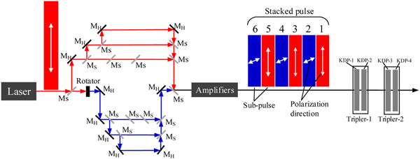
In this work, we propose a method to suppress TSRS in large-aperture third-harmonic-generation KDP crystals based on reconstruction of the 1ω laser pulse using pulse stacking, as shown in Figure 2. In a similar manner to conventional pulse stacking, a stacked pulse is constructed by stacking several narrower subpulses in chronological order. However, unlike conventional pulse stacking, the polarization directions of the adjacent subpulses in this case are perpendicular to each other. Therefore, when the stacked pulse is injected into the KDP crystal, the Stokes light that is generated by one subpulse cannot be continuously amplified by the other subpulses with their different polarization directions. The TSRS gain of the entire stacked pulse is thus lower than the corresponding gain of a single pulse (not formed by stacking of subpulses) with the same intensity and temporal width. The TSRS suppression method proposed in this study is called pulse stacking.

Fig. 2. Schematic diagram of proposed optical arrangement for pulse stacking scheme. M S: semi-transparent and semi-reflecting mirrors; M H: high-reflectivity mirrors.
Figure 2 shows an example of a pulse stacking scheme that we designed using six subpulses. To minimize the energy losses, we placed the pulse stacking setup before the amplifiers. All the subpulses were generated by the same laser source, and pulse stacking is established by adjusting the optical path delay. In addition, while the 1ω pulse only requires one frequency tripler in the conventional optical path, two frequency triplers are required here for the stacked 1ω pulse with its two polarization directions, as shown in Figure 2. Tripler-1 and tripler-2 transform the 1ω subpulses with horizontal (e.g., subpulses 1, 3, and 5 in Fig. 2) and vertical (e.g., subpulses 2, 4, and 6 in Fig. 2) polarizations, respectively, into 3ω subpulses. Therefore, tripler-1 and tripler-2 have identical physical parameters, but their optical axes are oriented differently. TSRS will be generated strongly in KDP-2 and KDP-4, particularly near their rear surfaces. Next, we use KDP-2 as an example to study the effects of the pulse stacking method on TSRS suppression.
The suppression effects of the scheme
For a conventional single laser pulse (without subpulse stacking), as shown in Figure 1a, with a width of 3 ns, we can calculate the flux damage threshold of the Stokes pulse in the KDP crystal as  $F_{{\rm th}} = 6\sqrt {\rm \tau} \,{\rm J/c}{\rm m}^2 = 10.4\,{\rm J/c}{\rm m}^2$ (where τ is the temporal width of the 3ω laser pulse in nanoseconds) (Sacks et al., Reference Sacks, Barker and Ehrlich1992). Using the value of F th and Eqs. (1) and (2), we can then calculate the threshold (or damage limit) intensity I th0 = 1.24 GW/cm2 for the 3ω laser pulse in the KDP crystal. In addition, for the simulations, it was assumed that the 3ω laser pulses were ideal rectangular pulses, and that the aperture size and the edge reflectivity of the KDP were 40 cm and 4%, respectively, the aperture of the laser beam was 36 cm, and the TSRS gain coefficient was 0.345 cm/GW. Next, we study the effects of pulse stacking on the threshold intensity I th of the 3ω laser beam in the KDP crystal. In the pulse stacking scheme, it should be noted that the subpulses and the stacked pulse (Fig. 2) are also assumed to be ideal rectangular pulses, and the stacked laser pulse width remains unchanged at 3 ns, so the widths of the subpulses are determined by the number of subpulses N. For example, the subpulse widths are 0.3 and 0.1 ns when N = 10 and 30, respectively.
According to the principle of pulse stacking and the scheme shown in Figure 2, the effect of pulse stacking on TSRS suppression is related to the number of subpulses used. Figure 3 shows the threshold intensity I th of the stacking pulse in the KDP crystal and its growth rate M (M = I th/I th0) as the number of subpulses N increases. As shown in Figure 3, the pulse stacking scheme can significantly increase the threshold intensity of the 3ω laser pulses in the KDP crystal, i.e., the proposed pulse stacking scheme can effectively suppress TSRS, and greater numbers of subpulses produce a more effective suppression effect. This occurs because the width of each subpulse becomes narrower as the number of subpulses increases, and there is a specific interval (i.e., the width of a subpulse) between adjacent subpulses with identical polarization directions, which means that the TSRS gain of the entire stacked pulse is significantly reduced. When N = 4, the threshold intensity can reach up to 2.31 GW/cm2, i.e., the threshold intensity growth rate of the 3ω laser in the KDP crystal reaches up to about 1.9. This is very easy to achieve in engineering. In addition, the threshold intensity I th fluctuates with respect to the parity of the number of subpulses N. This occurs because, when N is an odd number, the ratios of the energies of the odd numbered subpulses to the energy of the whole stacked pulse are 1, 2/3, 3/5, 4/7, …, (N + 1)/2 N, respectively; however, when N is an even number, the ratio of the energies of the odd numbered subpulses to the energy of the whole stacked pulse is always 1/2. Obviously, (N + 1)/2 N > 1/2; the differences in the laser energy cause fluctuations in the threshold intensity, and these fluctuations gradually decrease with increasing numbers of subpulses.

Fig. 3. Threshold intensity of 3ω laser pulses in the KDP crystal and its growth rate M versus the number of sub-pulses.
Summary and conclusion
In this work, a method to suppress TSRS in large-aperture KDP crystals using pulse stacking is proposed. The results of theoretical analyses and numerical simulations show that the pulse stacking method can suppress TSRS significantly, with greater numbers of subpulses producing more obvious suppression effects, and the threshold intensity growth rate of the 3ω laser in the KDP crystal reaches up to about 1.9 when the stacked pulse contains four subpulses. This is very easy to achieve in engineering. In addition, the method can also be used to suppress other nonlinear effects, including transverse stimulated Brillouin scattering in large-aperture optical devices and stimulated rotational Raman scattering over long air paths. We hope that this method can be of major significance in the efforts to suppress nonlinear effects in high-power laser systems.
Author ORCIDs
Xinmin Fan, 0000-0001-6208-9520
Acknowledgments
This work was supported by the Natural National Science Foundation of China (NSFC) (61701349, 61805178); Higher Education Science and Technology Project of Shandong, China (J16LJ54); and the Natural Science Foundation of Shandong Province (ZR2018PF016).