Introduction
Now-a-days, high-intensity, low emittance electron accelerators are required for many applications. One of the beam qualities demanded often for such advanced accelerators is the brightness. The brightness depends upon current as well as emittance. For a free electron laser (FEL), the electron beam emittance should be about λ, the wavelength of the radiation. Thus the emittance needs to be small for FEL operation at small wavelength. The current must also be high to ensure enough gain. Thus, electron beams for FEL need to be of high brightness. For application in high-energy physics, the high brightness is required to achieve high luminosity. Also, laser-plasma wakefield accelerator, linear colliders, and accelerator for neutron production require sub-picosecond high-brightness beam.
Sub-picosecond electron beam can be generated either using the pico- to femto-second laser or magnetic bunch compression, but they are either limited by the total charge or the emittance growth. Experimental observations and multiparticle simulations indicate that nonlinear space-charge forces of such high-intensity beams in accelerators develop a low-density halo at the periphery of the central core of the beam. They contribute to shape the beam density profile. This outer part of the distribution will lead to particle loss and hence degradation of accelerator components. The major challenge is to control the beam profile. Collimation of beam halo will not solve the problem because the halo may re-develop after further propagation (Allen and Wangler, Reference Allen and Wangler2002; Nghiem et al., Reference Mondelaers and Schillebeeckx2011, Reference Nghiem, Chauvin, Comunian, Delferrière, Duperrier, Mosnier, Oliver and Uriot2012; Wittenberg, Reference Wittenberg2014).
There are many reasons for the formation of beam halo-like mismatch of the beam with the accelerator structure, transverse-longitudinal coupling in the RF (radio frequency) field, aberrations of focusing elements, Coulomb scattering within the beam and residual gases, and nonlinear space-charge forces (Fedotov et al., Reference Fedotov, Gluckstern, Kurennoy and Ryne1999; Allen and Wangler, Reference Allen and Wangler2001; Fedotov, Reference Fedotov2003). Over the years, theoretical studies and numerical simulations on the physics of beam halo has been extensively performed. In the low-energy region, electrostatic repulsion among particles become prominent (Chao et al., Reference Chao, Pitthan, Tajima and Yeremian2003; Reiser, Reference Proch2008; Stupakov and Huang, Reference Stephan, Boulware, Krasilnikov, Bähr, Asova, Donat, Gensch, Grabosch, Hanel, Hakobyan, Henschel, Ivanisenko, Jachmann, Khodyachykh, Khojoyan, Köhler, Korepanov, Koss, Kretzschmann, Leich, Lüdecke, Meissner, Oppelt, Petrosyan, Pohl, Riemann, Rimjaem, Sachwitz, Schöneich, Scholz, Schulze, Schultze, Schwendicke, Shapovalov, Spesyvtsev, Staykov, Tonisch, Walter, Weisse, Wenndorff, Winde, Vu, Dürr, Kamps, Richter, Sperling, Ovsyannikov, Vollmer, Knobloch, Jaeschke, Boster, Brinkmann, Choroba, Flechsenhar, Flöttmann, Gerdau, Katalev, Koprek, Lederer, Martens, Pucyk, Schreiber, Simrock, Vogel, Vogel, Rosbach, Bonev, Tsakov, Michelato, Monaco, Pagani, Sertore, Garvey, Will, Templin, Sandner, Ackermann, Arévalo, Gjonaj, Müller, Schnepp, Weiland, Wolfheimer, Ronsch and Rossbach2008; Wang, Reference Stupakov and Huang2009). An obvious way to suppress these space-charge forces is to choose a beam distribution with a lower degree of space-charge nonlinearity. It is well known that a hollow beam has lesser space-charge force than a uniformly distributed beam (Humphreis, Reference Koepke2002; Pathak and Krishnagopal, Reference Park, Choi, Ha, Han, Hong, Hwang, Kang, Kang, Kim, Kim, Kim, Ko, Lee, Lee, Lee, Min, Park, Son and Chae2015; Dash et al., Reference Dash, Nayak, Sharma and Mittal2016). To study beam halo in electron and proton beams, various experiments have been conducted. In ELSA photo-injector, by varying the focusing strength of anode coil and bunch charge of the electron beam, halo has been observed and gradual change in beam profile is noticed (Haouat et al., Reference Han, Baek, Chae, Choi, Ha, Hong, Hu, Hwang, Jung, Kang, Kim, Kim, Kim, Kim, Kim, Ko, Lee, Lee, Lee, Lee, Min, Mun, Na, Park, Park, Park, Son and Yang1995). Similarly at Los Alamos, proton beam-halo experiment in a 52-quadrupole periodic-focusing channel has been conducted and the results are qualitatively consistent with the particle-core model of halo formation in mismatched beams (Colestock et al., Reference Colestock, Wangler, Allen, Sheffield, Gilpatrick, Thuot, Schulze and Harvey2000; Wangler and Qiang, Reference Wang2002).
In this paper, we discuss beam halo induced due to intense space-charge effect in an electron linac. The paper is divided mainly into two sections. In the first part, description of accelerating and magnetic focusing elements will be presented. In the second part, beam dynamics performed in ASTRA will be discussed in a detailed manner.
Description of accelerator
RF photoinjectors have been under intensive development for the past decade since they promise to be the high-brightness electron beam sources required for FELs. The invention of the photocathode gun and the concepts of emittance compensation in the presence of space-charge and RF forces have made these high-quality beams possible. Photo-cathode guns are used to produce and accelerate intense beams (high charge per bunch). The basic advantage compared with the thermionic gun is that the current density delivered by semiconductor photoemitters is very high. Furthermore, the time structure can be controlled by the laser beam, so that the beam pulse duration can be tailored to match into the RF accelerators without degrading the emittance. A high accelerating field gradient in the laser photocathode RF gun accelerates electrons to relativistic speed within a very short distance, thereby reducing the Coulomb repulsion between the particles in the beam (Table 1). Hence there is a lower emittance growth produced by space-charge forces. However, the minimum emittance attainable is still limited at high current levels by the space-charge effects. Achieving such beams at the end of the linac requires taking a finer resolution view of the electron dynamics near the cathode during photoemission and the initial acceleration of the beam.
Table 1. Parameters of Tesla cavity from CST simulation

The Linac Coherent Light Source (LCLS) is a SASE (self-amplified spontaneous emission) FEL at SLAC. Its injector consists of a RF photocathode gun from which 1 nC bunch charge is extracted (Akre et al., Reference Akre, Dowell, Emma, Frisch, Gilevich, Hays, Hering, Iverson, Limborg-Deprey, Loos, Miahnahri, Schmerge, Turner, Welch, White and Wu2008). The photoinjector test facility at DESY, Zeuthen site (PITZ) is used for high-brilliance, short-wavelength FEL applications like the free-electron laser in Hamburg (FLASH) and the European x-ray free-electron laser (XFEL). Here, electron beams with a bunch charge of 1 nC have been demonstrated (Stephan et al., Reference Shintake, Tanaka, Hara, Tanaka, Togawa, Yabashi, Otake, Asano, Bizen, Fukui, Goto, Higashiya, Hirono, Hosoda, Inagaki, Inoue, Ishii, Kim, Kimura, Kitamura, Kobayashi, Maesaka, Masuda, Matsui, Matsushita, Maréchal, Nagasono, Ohashi, Ohata, Ohshima, Onoe, Shirasawa, Takagi, Takahashi, Takeuchi, Tamasaku, Tanaka, Tanaka, Tanikawa, Togashi, Wu, Yamashita, Yanagida, Zhang, Kitamura and Ishikawa2010). Many other FEL facilities at other laboratories around the world are: PAL-XFEL injector test facility at the Pohang Accelerator Laboratory (PAL), the SPring8 Compact SASE Source (SCSS) test accelerator at RIKEN, Shanghai Deep Ultraviolet FreeElectron Laser source (SDUV-FEL) SwissFEL at PSI, and so on (Zhao et al., Reference Zhao, Dai, Zhao, Liu, Zhou, He, Jia, Chen and Dai2004; Shintake et al., Reference Schietinger, Pedrozzi, Aiba, Arsov, Bettoni, Beutner, Calvi, Craievich, Dehler, Frei, Ganter, Hauri, Ischebeck, Ivanisenko, Janousch, Kaiser, Keil, Löhl, Orlandi, Ozkan Loch, Peier, Prat, Raguin, Reiche, Schilcher, Wiegand, Zimoch, Anicic, Armstrong, Baldinger, Baldinger, Bertrand, Bitterli, Bopp, Brands, Braun, Brönnimann, Brunnenkant, Chevtsov, Chrin, Citterio, Csatari Divall, Dach, Dax, Ditter, Divall, Falone, Fitze, Geiselhart, Guetg, Hämmerli, Hauff, Heiniger, Higgs, Hugentobler, Hunziker, Janser, Kalantari, Kalt, Kim, Koprek, Korhonen, Krempaska, Laznovsky, Lehner, Le Pimpec, Lippuner, Lutz, Mair, Marcellini, Marinkovic, Menzel, Milas, Pal, Pollet, Portmann, Rezaeizadeh, Ritt, Rohrer, Schär, Schebacher, Scherrer, Schlott, Schmidt, Schulz, Smit, Stadler, Steffen, Stingelin, Sturzenegger, Treyer, Trisorio, Tron, Vicario, Zennaro and Zimoch2006, Reference Shintake, Hara, Higashiya, Inagaki, Maesaka, Otake, Shirasawa, Tanaka, Togawa, Yabashi, Baba, Onoe, Tanaka, Matsumoto and Tanikawa2008; Park et al., Reference Nghiem, Chauvin, Simeoni and Uriot2013; Han et al., Reference Halbach and Holsinger2014; Schietinger et al., Reference Reiser2016).
The n-TOF-facility GELINA at Belgium has been especially designed and built for high-resolution cross-section measurements. The GELINA neutron source is based on a linear electron accelerator. It consists of thermionic electron gun, a pre-buncher, standing wave buncher with traveling wave accelerating structure operating at 2π/3 mode, and other magnetic elements for focusing and compressing the beam. It uses a 10 nsec, 10 Amp pulsed beam where charge per bunch in one RF cycle is around 3 nC (Bensussan and Salome, Reference Bensussan and Salome1978; Mondelaers and Schillebeeckx, Reference Li and Tang2006).
Considering this scenario, we observe that the performance of high-brilliance, short-wavelength FELs is critically dependent on the quality of the electron beam driving the FEL process, and lesser emittance growth with more transmission efficiency will be required for neutron productions. In all these cases, beams of around 1–3 nC have been considered and demonstrated. With further increase in charge, phase space gets distorted and beam loss with beam halo increases (Kim, Reference Humphreis1986, Reference Kim1989; Carlsten, Reference Carlsten1989). Hence the quest will always be to generate and accelerate higher brightness beams with better quality. In this paper, we analyze a scheme of using hollow electron beams to compensate for such effects and to achieve the minimum growth of emittance available from a photoemitter injector.
In this paper, to show the advantages of hollow electron beam, we have considered a typical example and studied its dynamics in a 17 MeV RF linac which consists of 1.3 GHz RF gun and a nine-cell superconducting cavity as shown in Figure 1. Design of the RF gun was carried out in Superfish and is shown in Figure 2a (Halbach and Holsinger, Reference Floettmann1987). The design is similar to the one used in the Fermilab photoinjector (Colby et al., Reference Colby, Bharadwaj, Ostiguy, Nicol, Conde and Rosenzweig1996; Carneiro et al., Reference Carneiro, Edwards, Fitch and Hartung2000, Reference Carneiro, Barov, Edwards, Fitch and Hartung2005; Piot et al., Reference Pathak and Krishnagopal2005). It consists of a 1.625 cell resonating in the TM010 π-mode. Bore aperture is 40 mm.

Fig. 1. Schematic representation of the accelerator.
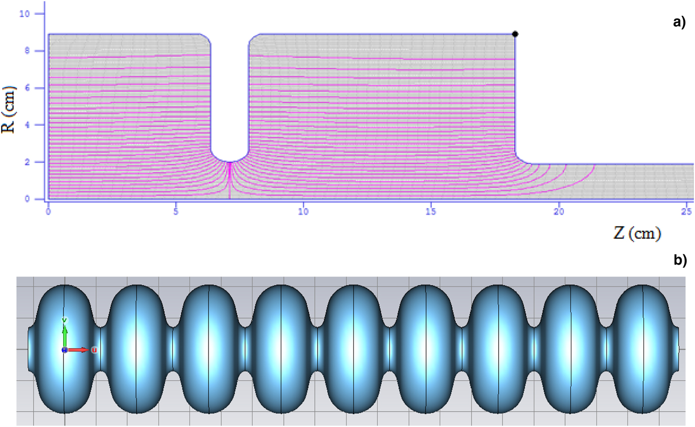
Fig. 2. (a) Superfish model of the RF gun where the contours represent the electric field pattern of TM010 mode. (b) The nine-cell TESLA cavity as modeled in CST Microwave Studio.
Superconducting TESLA cavity resonating at 1.3 GHz is designed in CST Microwave Studio and its model is shown in Figure 2b (Proch, Reference Piot, Edwards, Huening, Koeth, Li and Tikhoplav1993; Weise, Reference Wangler and Qiang1994; Koepke, Reference Haouat, Pichoff, Couillaud, De Brion, Di Crescenzo, Joly, Loulergue, Ruiz, Seguin and Striby1995; Aune et al., Reference Aune, Bandelmann, Bloess, Bonin, Bosotti, Champion, Crawford, Deppe, Dwersteg, Edwards, Edwards, Ferrario, Fouaidy, Gall, Gamp, Gössel, Graber, Hubert, Hüning, Juillard, Junquera, Kaiser, Kreps, Kuchnir, Lange, Leenen, Liepe, Lilje, Matheisen, Möller, Mosnier, Padamsee, Pagani, Pekeler, Peters, Peters, Proch, Rehlich, Reschke, Safa, Schilcher, Schmüser, Sekutowicz, Simrock, Singer, Tigner, Trines, Twarowski, Weichert, Weisend, Wojtkiewicz, Wolff and Zapfe2000; Zu and Chen, Reference Zu and Chen1993). The electric field profile of RF gun and cavity section is plotted in Figure 3.

Fig. 3. Field profile of the RF gun and cavity.
For a peak RF field at the cathode of 40 MV/m and accelerating field gradient of 24 MV/m, the beam gains an energy of 4.5 MeV at the exit of gun and 17 MeV at the exit of the cavity, with an energy spread of 70 keV for 15 nC charge.
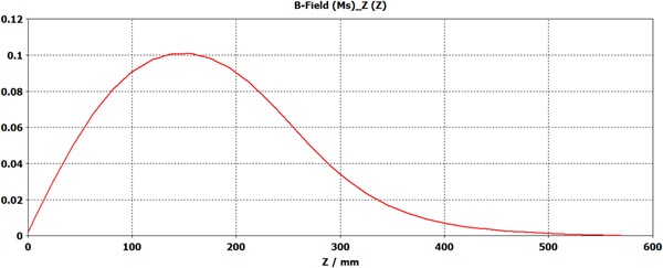
To confine the space-charge dominated beam, a solenoid is used after the gun and a bucking solenoid is used to cancel the longitudinal magnetic field on the cathode (Grivet, Reference Grivet1972; Li and Tang, Reference Kim2007). The solenoids have been simulated in CST Microwave Studio. The bucking coil is exactly same (but field in opposite direction) as focusing solenoid after RF gun. The focusing coil is an iron core solenoid which consists of 120 number of turns and 200 A current flows through it to produce a peak field of 1000 Gauss. Inner and outer diameter of the coil is 70 and 240 mm. Length of the coil is 275 mm. Outer diameter of the solenoid is 300 mm. The model of solenoid and field profile after photocathode (along the beam direction) are shown in Figures 4 and 5.

Fig. 4. Model of the iron core solenoid.
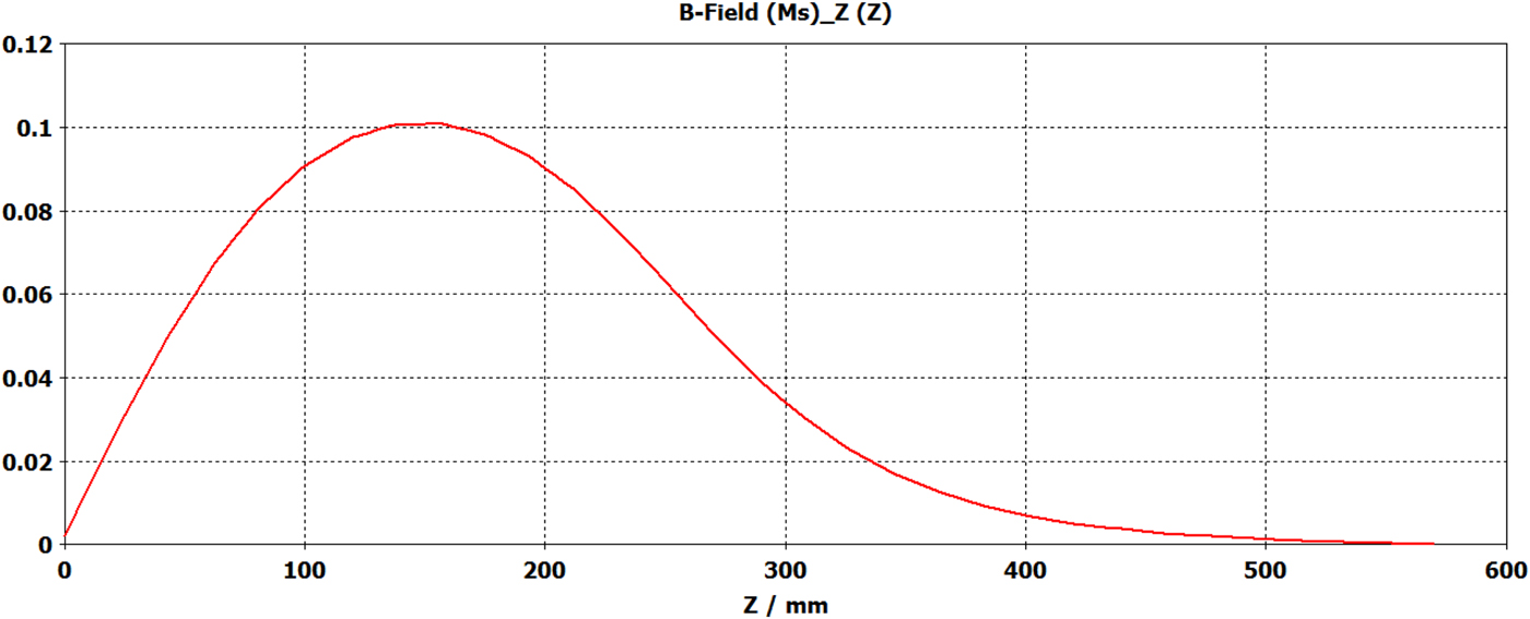
Fig. 5. Field profile along beam propagation direction.
Simulation results of beam dynamics studies
This section is divided into two parts. In part “Dynamics of hollow beam”, results of simulations have been discussed, and in part “Variation of halo parameter with distance and hollowness of input beam”, variation of halo parameter with distance and hollowness of input beam have been analyzed.
Dynamics of hollow beam
ASTRA is a multiparticle beam dynamics code which tracks particles through external electric and magnetic fields, taking into account the space-charge field (linear and nonlinear) of the bunch (Floettmann, Reference Floettmann2017). The initial transverse and longitudinal particle distributions are read from an external file. We perform the beam dynamics analysis using ASTRA by varying the bunch charge from 4 to 15 nC. In the simulation, we assumed a bunch of full width of 10 ps. The transverse laser distribution is assumed perfectly uniform in both x- and y-directions. In the input, a uniformly distributed beam of size 8 mm and a hollow beam of the almost same area 16 πmm2 (outer radius 5.5 mm, inner radius 3.7 mm) are considered. Input beam size and density distribution for uniform and hollow beams are shown in Figures 6 and 7.

Fig. 6. Input beam distribution for the uniform beam.

Fig. 7. Input beam distribution for the hollow beam.
Comparison of transverse phase space plots and normalized particle density distribution for three cases, that is, 6, 10, and 15 nC for uniform and hollow beams at the end of the linac is shown in Figures 8–10.

Fig. 8. Phase space plot and density distribution for 6 nC case.

Fig. 9. Phase space plot and density distribution for 10 nC case.

Fig. 10. Phase space plot and density distribution for 15 nC case.
It is found from Figures 8–10 that in each of the cases, phase space is distorted and hence emittance growth occurs. But looking at the particle density, it may be observed that in case of uniform beam, particles are distributed uniformly within the beam. In case of hollow beam, most of the particles are situated within a core. Now to observe the distribution of particles inside the beam, let us compare the case of 10 nC which is plotted in Figures 11.
Fig. 11. Beam size at the exit of accelerator for 10 nC case.
For the uniform beam, size is more and density of the particles gradually decreases from the center to the outer edge. For the hollow beam, most of the particles are confined within a dense core and very few particles are scattered outside. Hence the size is smaller in this case.
It is known that a Gaussian distributed beam has a nonlinear charge density distribution as it is proportional to  $e^{ - r^2/2{\rm \mu} ^2}$ where μ is the RMS (root mean square) beam size. Hence because of space-charge nonlinearity, phase space will be distorted more. So let us perform some simulation by taking a Gaussian beam of full size (3 µ) 8 mm as of uniform beam and calculate the dynamics of the beam. Below Figures 12 and 13 show the phase space and density distribution at the exit of accelerator for charges of 10 and 15 nC.

Fig. 12. Phase space plot and density distribution for 10 nC case.

Fig. 13. Phase space plot and density distribution for 15 nC case.
From Figures 12 and 13, it is observed that for charges of 10 and 15 nC, the beam size is more as compared with uniform beam and it remains no more Gaussian.
Normally small fraction of particles surrounding a dense beam core is called halo but there is no clearly defined separation between the halo and main core of the beam. That is why the question always arises where is the core part and where the halo part is? However in the literature, halo parameter is generally defined as the ratio of fourth moment of beam distribution to the second moment (Allen and Wangler, Reference Allen and Wangler2002; Nghiem et al., Reference Nghiem, Chauvin, Comunian, Delferrière, Duperrier, Mosnier, Oliver and Uriot2011, Reference Nghiem, Chauvin, Simeoni and Uriot2012; Wittenberg, Reference Wittenberg2014). The halo parameter H identifies the amount of halo in a particular beam distribution. Halo parameter for a continuous uniform distribution is 0, for a Gaussian distribution, it is 1, and for a parabolic distribution, it is 0.25. Halo parameter in one dimension is essentially the kurtosis of the beam. Also beam halo in one-dimensional spatial projection may oscillate along the beam line, so it is better to calculate halo in two-dimensional phase space (position and momentum).
H is constructed from the second and fourth spatial moments of the beam. A general characteristic of a beam halo is the increased population of the outer part of the beam. Let the co-ordinate of the i th phase plane be (x i, p i), where x i and p i are the spatial and momentum coordinates.
The halo parameter for a buncher beam in the i th plane is defined as
 $$H_i = \displaystyle{{\sqrt {3x_i^4 p_i^4 + 9x_i^2 p_i{^2} ^2 - 12x_ip_i^3 p_ix_i^3}} \over {2x_i^2 p_i^2 - 2x_ip_i^2}} - 2.15$$
Significant halo corresponds to H i >1.
The normalized RMS emittance is defined by
 $${\rm \varepsilon }_{n,rms} = {\rm \beta \gamma }\sqrt {\langle{r}^2\rangle {\langle r^{\prime 2}\rangle}- \langle r{r^{\prime}\rangle{}^2}}$$
where βc is the velocity of the beam, γ is the Lorentz factor, r and r′ are the transverse co-ordinate and divergence of x or y and 〈 〉denotes RMS value (Carlsten, Reference Carlsten1998; Chen et al., Reference Chen, Pakter and Davidson1999; Franchetti, Reference Franchetti2001; Eshraqi et al., Reference Eshraqi, Franchetti and Lombardi2009).
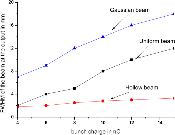
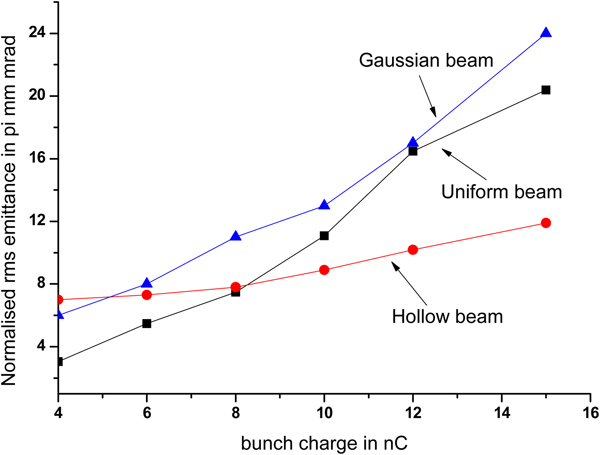
From Figures 14 and 16, it is observed that for a uniformly distributed beam, with increase of bunch charge from 4 to 15 nC, beam size (here for reference we have considered FWHM instead of RMS, for Gaussian distribution FWHM = 2 $\sqrt 3 \; $ RMS) increases from 2 to 12 mm, and the normalized RMS emittance from 3 to 20 π mm-mrad. For a hollow beam, FWHM increases from 2 to 3.5 mm and emittance from 7 to 12 π mm-mrad. For a Gaussian beam, beam size increases from 7 to 18 mm with emittance from 6 to 24 π mm-mrad. For uniform beam, the emittance growth is faster and it does not increase linearly with bunch charge. For hollow beam, it varies very slowly. From 4 to 8 nC, it remains almost same and then gradually increases.

Fig. 14. Beam size (FWHM) at the exit of accelerator as a function of bunch charge.
Similarly from Figure 15, halo parameter for an uniform beam decreases from 3.7 to 1.9. For Gaussian beam, halo parameter decreases from 3.22 to 1.68 for 15 nC charge, but for a hollow beam, H increases from 1.2 to 1.61. With further increase of bunch charge beyond 15 nC, halo parameter again increases for a hollow beam. It is found that with increase of charge for uniform and Gaussian beam, FWHM of the beam increases with simultaneous reduction of tail part of the beam. So halo parameter decreases with bunch charge for these two distributions. Hence it is found that for low charge per bunch (i.e., at 4 nC), uniform beam is better, but for charge like 12–15 nC, beam quality for hollow beam improves a lot in terms of transverse emittance and production of halo.
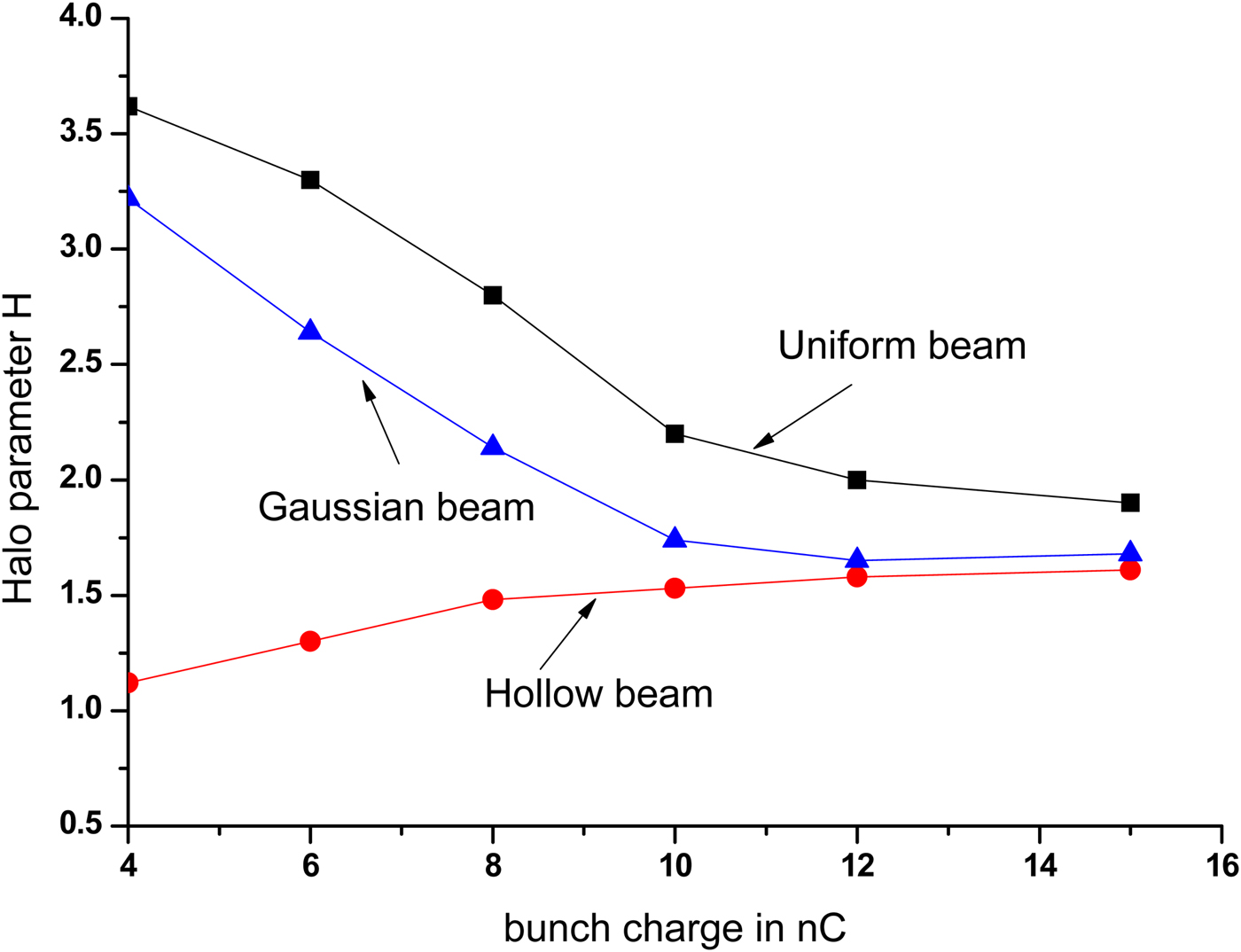
Fig. 15. Halo parameter at the exit of accelerator, as a function of bunch charge.
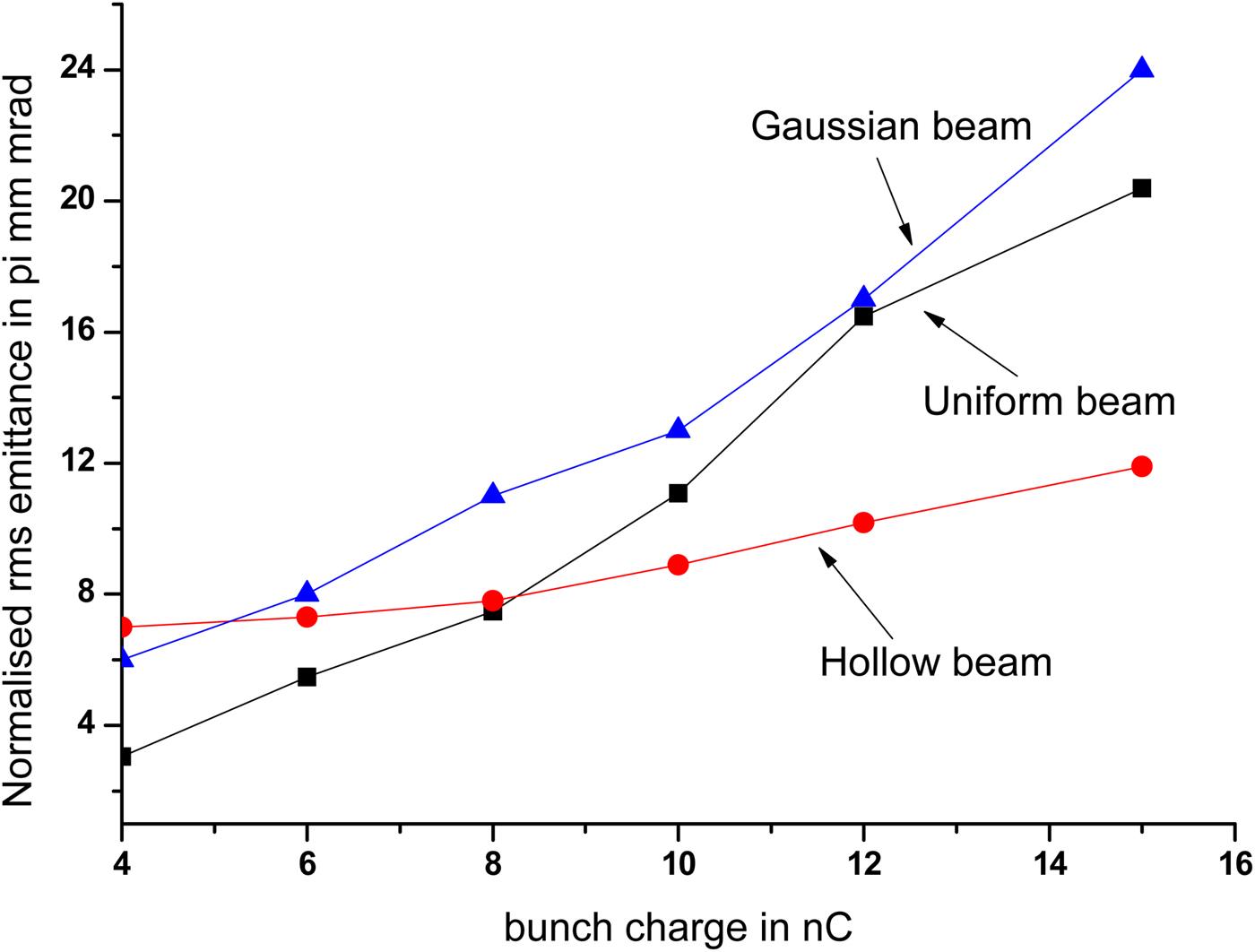
Fig. 16. RMS normalized emittance at the exit of accelerator as a function of bunch charge.
Variation of halo parameter with distance and hollowness of input beam
Now let us find out how the hollowness of the beam changes in the z-direction, that is, along the beam acceleration direction. For that, we have taken three cases, that is, bunch of charge 2, 4, and 15 nC. The phase space plot and beam density distribution are shown in Figures 17–19. In this case, simulation is run up to the exit of the RF gun.

Fig. 17. Phase space plot and beam distribution at the exit of the RF gun for 2 nC bunch charge.

Fig. 18. Phase space plot and beam distribution at the exit of the RF gun for 4 nC bunch charge.

Fig. 19. Phase space plot and beam distribution at the exit of the RF gun for 15 nC bunch charge.
From Figures 17–19, it is found that hollowness of the beam diminishes with increase in bunch charge, and even at the exit of RF gun, it attains a uniformly distributed beam for higher charge. So advantage of using a hollow of the beam to compensate space charge and minimize halo retains up to the injector section. After that, addition of further any number of cavities is only to accelerate the particle and increase its energy.
Now we investigate the variation of the halo parameter with hollowness of the input beam. For that two cases have been presented here. Keeping the outer diameter fixed at 11 mm, we considered inner diameters of 3 and 5 mm. The input beam size and output beam distribution for these two cases have been shown in Figures 20 and 21. For this study, the bunch charge was 15 nC.

Fig. 20. Input beam size of inner diameter 3 mm and output beam distribution.

Fig. 21. Input beam size of inner diameter 5 mm and output beam distribution.
For a hollow beam of inner diameter 3 mm, FWHM of the beam is 6 mm and RMS normalized emittance is 18 π mm-mrad, whereas for the 5 m case, the FWHM is 5 mm and the emittance is 15 π mm-mrad. From this, it is observed that as hollowness of input beam increases, beam quality improves, but beyond certain beam emission area, it may be difficult to extract such high charge (15 nC) from photocathodes. That is why here the study has been focused on the beam of inner diameters 3, 5, and 7.0 mm, respectively.
Comparison of hollow beam and uniformly distributed beam for an optimized condition
Throughout the paper, we have compared and discussed the advantages of hollow beam over uniformly distributed beam (uniform and Gaussian distribution) and we showed that keeping a particular magnetic field (0.1 T) and bunch length (10 ps) fixed, the nonlinear component of space charge (which basically distorts the beam distribution and causes the growth of emittance) can be compensated by using a hollow beam, but all these calculations are performed without optimizing the magnetic field and bunch length.
Now first we will optimize the magnetic field to find the minimum growth of emittance and compare uniformly distributed beam with hollow beam at the exit of linac. We will vary the magnetic field from 0.07 to 0.18 T and carry out the simulation. First we will perform simulation for 4 nC charge.
From Figure 22, it is found that minimum emittance for 4 nC charge for uniform distribution is 1.4 π mm-mrad at 1200 Gauss, and for Gaussian and hollow distribution, it is 2.2 and 1.7 π mm-mrad, respectively.
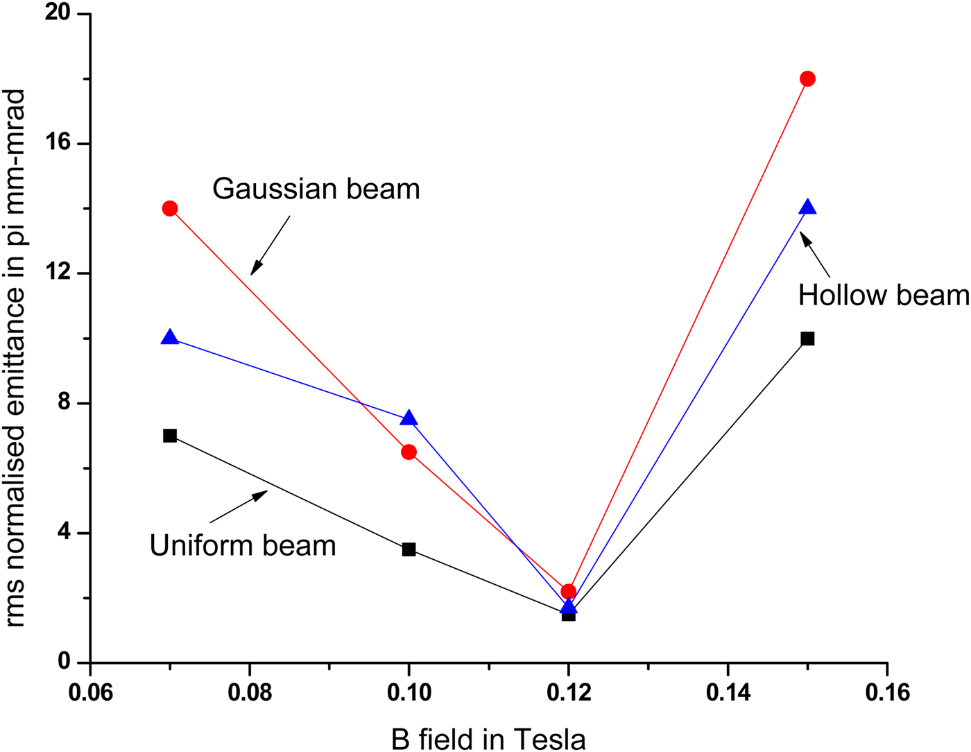
Fig. 22. Variation of normalized emittance at the end of linac with B field for 4 nC charge.
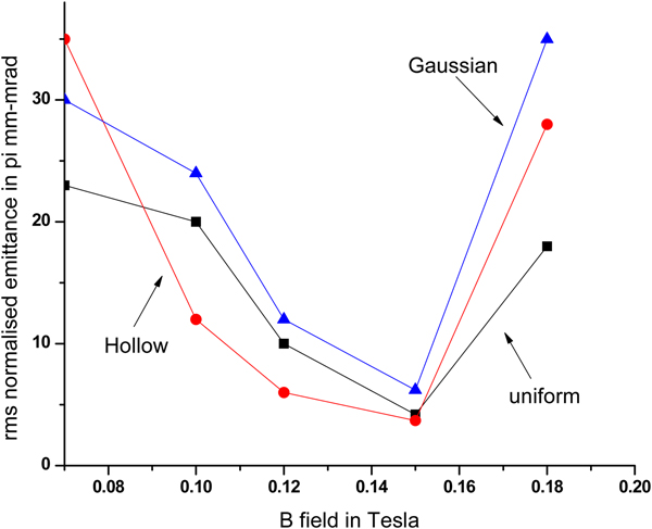
Next we will calculate the emittance growth for 15 nC charge. In Figure 23, the variation of RMS normalized emittance at the end of accelerator as a function of magnetic field is plot. We find that the optimized RMS normalized emittance for uniform distribution beam is 4.2 π mm-mrad, whereas for hollow and Gaussian beam, it is 3.7 and 6.2 π mm-mrad at a B field of 0.15 T, beyond that beam emittance again starts increasing. Also halo parameter for uniform beam is 1.7, whereas for hollow beam, it is 1.24.

Fig. 23. Variation of normalized emittance at the end of the linac with B field for 15 nC charge.
Figures 22 and 23 show that, if we optimize the solenoid field in this case, the difference of emittance growth for the different particle distributions can be almost removed.
Now keeping this magnetic field fixed at 0.15 T and bunch charge 15 nC, we will vary the bunch length from 5 to 20 ps and find out the optimized emittance. With increase of bunch length, the space-charge effect decreases, as a result of which emittance should decrease.
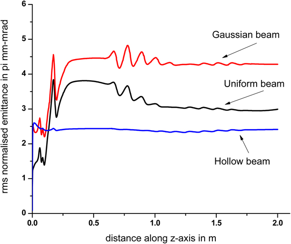
It is observed from Figure 24 that RMS normalized emittance decreases with increase of bunch length. For 5 ps bunch, the emittance for uniform, Gaussian, and hollow beam is 6.5, 7.3, and 5.0 π mm-mrad, whereas for 20 ps bunch, it is 3.0, 4.3, and 2.4 π mm-mrad. The variation of emittance with distance along linac axis (let us take it as z-axis) is plotted in Figure 25. For uniform, Gaussian, and hollow beam, the emittance almost remains constant from exit of photoinjector to end of linac (although in case of uniform beam, it slightly decreases). So for uniform and Gaussian beam, the growth of emittance is more than that of hollow beam.
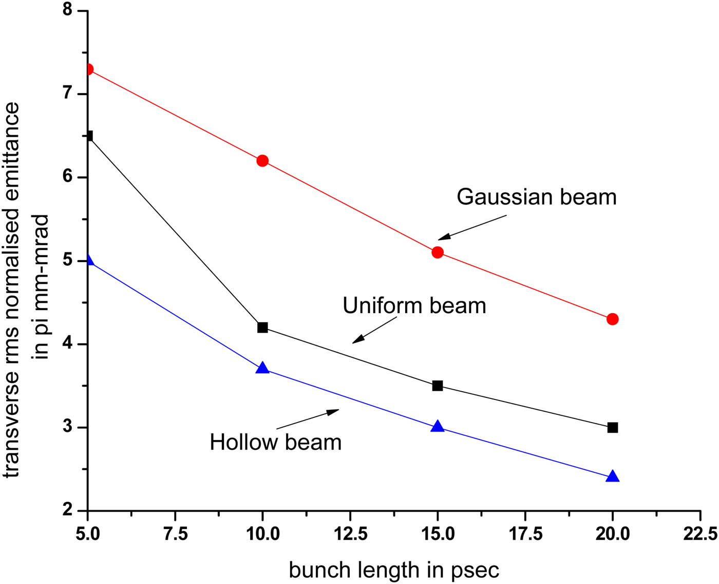
Fig. 24. Variation of normalized emittance at the exit of linac with bunch width.

Fig. 25. Growth of transverse emittance along the axis of the linac.
Hence it is found from these studies that clearly for unoptimized case, use of hollow beam has more advantages, and also with proper optimization, one can achieve better beam quality (lesser emittance and halo as discussed above from Figures 24 and 25) by using a hollow beam in the linac.
Conclusion and future studies
Halo formation is an important issue in intense charged particle beams. With increasing halo proportion, the power stored in it can become significant. As a consequence, a careful analysis of the profile can help revealing the internal dynamics of the beam. Indeed, the halo is the main contributor to particle losses downstream, which must be maintained under specified levels. In high-intensity linacs, the low energy and high perveance makes the beam sensible to space-charge effects. As a consequence, beam distributions are often far from Gaussian. Here, we have performed multiparticle simulations to explore the possibility of using hollow beam for suppression of halo growth. Simulation results show a significant beam quality improvement in terms of emittance growth and halo production for a hollow beam as compared with a uniform and Gaussian beam. Also we found that hollowness of beam has advantages up to exit of injector section (where space-charge forces cannot be neglected), after that addition of any number of accelerating section is to increase its energy. Further studies involves the generation of hollow beam from photocathodes.
Acknowledgment
The authors would like to express sincere gratitude to Shri S. Acharya, Dr Vinit Kumar, Dr Archana Sharma, and R. K. Rajawat for the valuable discussion and support for this work.