Introduction
High intensity laser guiding over lengths greater than centimeters is one of the key issues for future laser-plasma accelerators (Tajima and Dawson, Reference Tajima and Dawson1979; Modena et al., Reference Modena, Najmudin, Dangor, Clayton, Marsh, Joshi, Malka, Darrow, Danson, Neely and Walsh2002) and other applications such as X-ray lasers (Faenov et al., Reference Faenov, Magunov, Pikuz, Skobelev, Gasilov, Stagira, Calegari, Nisoli, Silvestri, Poletto, Villoresi and Andreev2007), harmonic generation (Malka et al., Reference Malka, Modena, Najmudin, Dangor, Clayton, Marsh, Joshi, Danson, Neely and Walsh1997; Gupta and Singh, Reference Gupta and Singh2016), and so on. In laser plasma accelerators (Esarey et al., Reference Esarey, Schroeder and Leemans2009), the pondero intense laser beam drives a plasma wave that can accelerate particles to extremely high energies. The performance of such accelerators can be greatly enhanced by guiding the drive laser beam, which must be at or above an intensity 1018 W/cm2 to produce high accelerating fields. To reach GeV energies, cm-scale acceleration distances are required. However, in the absence of an optical guiding mechanism, diffraction broadening of the laser beam limits the interaction length only up to a Rayleigh length. Hence, guiding of laser beams is essential to enhance the performance of the laser-driven accelerators. By maintaining the laser intensity over several Rayleigh lengths, controlled guiding can allow efficient production of a long, high gradient wake structures. In conventional optics, one can obviate the diffraction broadening of the laser beams by using optical fibers. In applications involving laser–plasma interactions laser beams having intensities over 1018 W/cm2 are being used. However, glass fibers undergo ionization induced damages only at 1012 W/cm2. But by using plasma channels, that are impervious to optical damage, as the guiding medium, such limitation could be significantly surpassed. Plasma channels, thus offer a practical solution to the problem of extending the interaction lengths beyond the limit set by geometric diffraction (Esarey et al., Reference Esarey, Sprangle, Krall and Ting1997).
Plasma channels have been created in the laboratory by a variety of methods: (1) Passing a long laser pulse through an optic to create a line focus in a gas, which ionizes and heats the gas, creating a radially expanding hydrodynamic shock (Clark and Milchberg, Reference Clark and Milchberg1997; Johnson et al., Reference Johnson, Dorney and Mittleman2001) (2) using a slow capillary discharge to control the plasma density profile (Ehrlich et al., Reference Ehrlich, Cohen, Zigler, Krall, Sprangle and Esarey1996) (3) using the ponderomotive force of an intense, relativistically self-guided laser pulse in a plasma which creates a channel in its wake (Young and Bolton, Reference Young and Bolton1996; Clayton et al., Reference Clayton, Tzeng, Gordon, Muggli, Mori, Joshi, Malka, Najmudin, Modena, Neely and Dangor1998).
The principle behind plasma channel guiding is that a plasma column that has a radial density profile with an on-axis minimum can, through the dependence of refractive index on plasma density, acts as lens for the laser beam. Guiding over long distances is possible due to the balance between the inward bending of the light rays through the refractive index gradient and outward expansion through geometric diffraction. To guide highly intense laser beams, plasma channels must be produced in deeply ionized gases, where the density profile cannot be changed by the guided beam through further ionization. An increase in density on axis would lead to ionization-induced refraction and hence negate the guiding (Leemans et al., Reference Leemans, Clayton, Mori, Marsh, Kaw, Dyson, Joshi and Wallace1992). To meet these requirements Volfbeyn et al. (Reference Volfbeyn, Esarey and Leemans1999) developed a novel technique which, rather than utilizing a single laser beam for ionization and heating, makes use of two laser beams. The physics of guiding the laser beam is as follows: The ignitor beam creates plasma by tunnel ionization of ambient gas. The heater beam heats the existing plasma and thus creates a concave parabolic electron density profile so that the plasma density becomes minimum on the axis as compared to the density at the edges of the channel where the density is maximum. Therefore, the refractive index becomes maximum on the axis and decreases towards the edges. The use of an ignitor beam reduces the energy requirements for the heater beam and allows better control of plasma parameters and reproducibility shot-to-shot than a single beam configuration.
When the third laser beam is passed through the plasma channel, it tends to diffract due to diffraction and converge due to nonlinear refraction under the combined effects of density nonuniformity of the plasma channel and relativistic mass nonlinearity of plasma electrons (Akhiezer and Polovin, Reference Akhiezer and Polovin1956). When both the convergence and divergence of the laser beam exactly balance each other, the laser beam propagates without any change in its spot size. However, in an axially nonuniform plasma channel, this condition cannot be satisfied throughout the plasma channel and hence the beam spot size changes as it propagates through the channel (Liu and Tripathi, Reference Liu and Tripathi1994).
Laser–plasma interactions are perennially fraught with copious nonlinear effects such as electron plasma wave excitation (Purohit et al., Reference Purohit, Chauhan and Sharma2008, Reference Purohit, Sharma and Sharma2010), stimulated Raman scattering (Sharma et al., Reference Sharma, Vyas and Singh2013; Rawat et al., Reference Rawat, Gauniyal and Purohit2014), stimulated Brillouin scattering (Sharma and Singh, Reference Sharma and Singh2013; Yadav et al., Reference Yadav, Gupta and Avinash2016), higher harmonic generation (HHG) (Malka et al., Reference Malka, Modena, Najmudin, Dangor, Clayton, Marsh, Joshi, Danson, Neely and Walsh1997; Gupta and Singh, Reference Gupta and Singh2016), and so on. Some of these phenomena lead to anomalous electron and ion heating and other to depleting or redirecting the incident laser flux and thus reduce the implosion efficiency of the fuel pellet in inertial confinement fusion. Therefore, to have deep insight into laser–plasma interaction physics, it becomes vital to investigate some of these phenomena by carrying out comprehensive studies encompassing theoretical as well as experimental aspects. Generation of higher harmonics of electromagnetic radiations in laser-produced plasmas is an important nonlinear process and has become an important field of research. Harmonic generation has a strong influence on the nature of laser propagation through plasmas. It allows penetration of laser power to over dense regions of the plasmas (Stamper et al., Reference Stamper, Lehmberg, Schmitt, Herbst, Young, Gardner and Obenshain1985) and thus has become an important diagnostic tool for obtaining information about plasma parameters such as electrical conductivity, expansion velocity, opacity, local electron density, and so on, via interferometry or absorption spectroscopy (Teubner and Gibbon, Reference Teubner and Gibbon2009). A classic example of this is second harmonic generation (SHG), which is routinely used to track the passage of intense laser beams through underdense plasma targets. Ultrafast pulse duration and good spatial and temporal coherence of harmonic radiations make them a good candidate for applications in vacuum ultraviolet or extreme ultraviolet regions. This includes ultrafast ionization of atoms, molecules or clusters in strong fields of short wavelengths, ultrafast spatial interferometry, ultrafast holography to investigate dynamics of surface deformations.
Higher harmonic generation is not the only technique for the generation of coherent light at short wavelengths. For this, various techniques are available, such as synchrotrons and free electron lasers. However, due to the typical size and related costs, these facilities are rather exclusive and access to them is limited. This impedes the progress in the fields of research associated with these facilities. In contrast, light sources based on HHG are much less expensive and can be accommodated in a table top device. These advantaged can bring coherent short-wavelength radiation sources within the reach of less affluent institutions, such as universities and hospitals. Another disadvantage of synchrotron radiations is that X-rays from synchrotrons cannot trace atomic motions inside a molecule or a solid. All we see is a dim blur, the pulses are nor short or bright enough. A synchrotron source can image molecules only if they are arranged in crystals, where the local forces hold millions of them in precise ranks like identical soldiers at attention. Laser harmonics, for their part, are brighter because they produce coherent light: The electromagnetic fields in laser harmonics are not choppy like the surface of a rough sea but smoothly oscillate with controlled regularity.
Harmonic generation of electromagnetic radiations in plasmas has been the subject of extensive study for quite some time. Early seminal works of Sodha et al. gave gravest blows to the studies on SHG of laser beams in plasmas (Sodha et al., Reference Sodha, Sharma and Kaw1968, Reference Sodha, Sharma, Tewari, Sharma and Kaushik1978). Hora and Ghatak (Reference Hora and Ghatak1985) derived and evaluated second harmonic resonance for perpendicular incidence at four times the critical density. Kant and Sharma (Reference Kant and Sharma2004) investigated second harmonic generation of short laser pulse in plasma by taking into consideration the effect of pulse slippage. Sukhdeep et al. investigated resonant second harmonic generation of Gaussian laser beam in collisional magnetoplasma. Agarwal et al. (Reference Agarwal, Pandey and Sharma2001) studied the resonant second harmonic generation of a millimetre wave in plasma in the presence of magnetic wiggler. The wiggler provides an additional momentum for the generation of harmonic photon. Singh and Walia (Reference Singh and Walia2011a, Reference Singh and Walia2011b, Reference Singh and Walia2013) investigated the effect of self-focusing of Gaussian laser beam on second harmonic generation in collisional (Reference Singh and Walia2011a), collisionless (Reference Singh and Walia2011b), and relativistic (Reference Singh and Walia2013) plasmas by using moment theory approach. Jha and Aggarwal (Reference Jha and Aggarwal2014) investigated the second harmonic generation of p-polarized laser beam in under dense plasma.
It is well-known fact that laser beams with different intensity profiles behave differently in plasmas. The investigations on SHG of laser beams in plasmas and plasma channels, till date, to the best of author's knowledge are limited to revealing the propagation characteristics of laser beams having Gaussian irradiance along their wavefronts. In contrast to this picture investigations on the intensity profile of the Vulcan Pettawatt laser at Rutherford Appelton laboratory by Patel et al. (Reference Patel, Key, Mackinnon, Berry, Borghesi, Chambers, Chen, Clarke, Damian, Eagleton, Freeman, Glenzer, Gregori, Heathcote, Hey, Izumi, Kar, King, Nikroo, Niles, Park, Pasley, Patel, Shepherd, Snavely, Steinman, Stoeckl, Storm, Theobald, Town, Maren, Wilks and Zhang2005) and Nakatsutsumi et al. (Reference Nakatsutsumi, Davies, Kodama, Green, Lancaster, Akli, Beg, Chen, Clark, Freeman, Gregory, Habara, Heathcote, Hey, Highbarger, Jaanimagi, Key, Krushelnick, Ma, MacPhee, MacKinnon, Nakamura, Stephens, Storm, Tampo, Theobald, Woerkom, Weber, Wei, Woolsey and Norreys2008) suggest that the intensity profile of the laser beam is not exactly Gaussian but is having deviations from it. The suggested intensity profile that fits with the experimental data is q-Gaussian of the form  $f(r) = f(0)(1 + (r^2/qr_0^2 ))^{-q}$, where the values of relevant parameters q and r 0 can be obtained by fitting the experimental data. The perturbations in the intensity profile of the laser beam may appear due to small obstacles of accidental nature (such as inclusions in the gain medium or in other optical elements of laser, dust particles etc). Fresnel diffraction on different apertures in a laser installation, including the hard edges of active elements, also play a prominent role in the origin of intensity perturbations. Literature review reveals the fact that no earlier theoretical investigation on SHG of q-Gaussian laser beams in plasma channels has been reported in the past. The aim of this paper is to investigate for the first time SHG of q-Gaussian Laser beam in plasma channel created by ignitor-heater technique.
Ionization of air
Consider the propagation of ignitor beam through air along z-axis. The field of the ignitor beam is given by
 $$\eqalign{E_1(r,z,t) &= E_1(r,z)e^{-{\rm \iota} ({\rm \omega} _0t-k_0z)}e_{\bi x} \cr E_1E_1^{\rm \star} = &\displaystyle{{E_{10}^2} \over {\,f_1^2}} e^{-(r^2/r_0^2 f_1^2 )}} $$
where r 0f 1 is the instantaneous spot size of the ignitor beam. Hence, the parameter f 1 is known as dimensionless beam width parameter which is measure of both spot size and axial intensity of the ignitor beam. The beam ionizes the air via tunnel ionization. We take air that predominantly comprisof nitrogen. Following Keldysh (Reference Keldysh1965), the rate of tunnel ionization of an atom is given by
 $${\rm \Gamma} = \displaystyle{{4{\rm \pi} e^4} \over {\hbar\! ^3}}\left( {\displaystyle{{E_i} \over {E_a}}} \right)^{5/2}\left( {\displaystyle{{E_a} \over {\vert {E_1} \vert }}} \right)e^{-(2/3)(E_a/\vert {E_1} \vert ){(E_i/E_a)}^{5/2}}$$
where E i is the ionization potential of the atom, E h is the ionization potential of hydrogen,
 $$E_a = \displaystyle{{m^2e^5} \over {\hbar \!^4}}\simeq 1.7 \times 10^7esu$$
is the atomic unit of electric field. The plasma density so formed is modeled by Liu and Tripathi (Reference Liu and Tripathi1994) as
 $${\rm \omega} _p^2 = {\rm \omega} _{\,p0}^2 e^{-({{E}^{\prime}}_a/\vert {E_1} \vert )}$$
where,
 $${E}^{\prime}_a = \displaystyle{2 \over 3}E_a\left( {\displaystyle{{E_i} \over {E_h}}} \right)^{1/2},{\kern 1pt} \quad {\rm \omega} _p^2 = \displaystyle{{4{\rm \pi} e^2} \over {m_e}}n_{e0}\quad {\rm and}\quad {\rm \omega} _{p0}^2 = \displaystyle{{4{\rm \pi} e^2} \over {m_e}}n_0.$$
The dielectric function of plasma is given by
 $${\rm \epsilon} _1 = 1-\displaystyle{{{\rm \omega} _p^2} \over {{\rm \omega} _0^2}} $$
 $${\rm \epsilon} _1 = 1-\displaystyle{{{\rm \omega} _{\,p0}^2} \over {{\rm \omega} _0^2}} e^{-({E}^{\prime}_a/\vert {E_1} \vert )}$$
Taking
 $${\rm \epsilon} _1 = {\rm \epsilon} _{01} + {\rm \phi} _1(E_1E_1^{\rm \star} )$$
where ε01 = ε1|r=0 is the axial part of the dielectric function and ϕ 1 is the off-axial part of the dielectric function, we get
 $${\rm \epsilon} _{01} = 1-\displaystyle{{{\rm \omega} _{p0}^2} \over {{\rm \omega} _0^2}} e^{-f_1({E}^{\prime}_a/E_{10})}$$
and
 $${\rm \phi} _1(E_1E_1^{\rm \star} ) = \displaystyle{{{\rm \omega} _{\,p0^2}} \over {{\rm \omega} _0^2}} \Big\{ {e^{-f_1({E}^{\prime}_a/E_{10})}-e^{-(\,f_1({E}^{\prime}_a/E_{10})e^{r^2/(2r_0^2 f_1^2 )})}} \Big\} $$
Formation of plasma channel
In order to slow down the process of electron ion recombination and to prolong the plasma, one launches the second beam (heater beam)
 $$E_2 = E_2(r,z)e^{-{\rm \iota} ({\rm \omega} _0t-k_0z)}e_{\bi x}$$
 $$E_2E_2^{\rm \star} = \displaystyle{{E_{20}^2} \over {\,f_2^2}} e^{-(r^2/(r_0^2 f_2^2 ))}$$
It imparts oscillatory velocity to plasma electrons
 $$v_2 = \displaystyle{{-e{\rm E}_2({\rm \nu} _{ei} + {\rm \iota} {\rm \omega} _0)} \over {m_e{\rm \omega} _0^2}} $$
where νei is the electron-ion collision frequency. The electron temperature rises and heats them at an average rate  $Re[-e{\bf E}_2^{\rm \star}. ({\bi v}/2)]$. The energy balance equation for the electrons is (Kumar et al., Reference Kumar, Dahiya and Sharma2010)
 $$\displaystyle{3 \over 2}\displaystyle{{dT_e} \over {dt}} = \displaystyle{{e^2 \vert {\rm E}_2 \vert ^2{\rm \nu} _{ei}} \over {2m_e{\rm \omega} _0^2}} -\displaystyle{3 \over 2}{\rm \delta} {\rm \nu} _{ei}[T_e-T_{e0}]$$
where δ is the mean fraction of excess energy lost per collision, T e is the field-dependent electron temperature, and T e0 is the equilibrium plasma temperature. Taking the variation of electron-ion collision frequency with electron temperature as νei = ν0(T e/T e0)−(3/2), ν0 is the electron-ion collision frequency at equilibrium plasma temperature. Equation (11) can be integrated to obtain the electron temperature as
 $$T_e = T_{e0}\left[ {1 + \displaystyle{{{\rm \beta}_2E_{20}^2} \over {\,f_2^2}} e^{-(r^2/r_0^2 f_2^2 )}} \right]$$
where  ${\rm \beta} _2 = (e^2M/6K_0T_{e0}m_e^2 {\rm \omega} _0^2 )$ is the coefficient of collisional nonlinearity. The nonuniformity in temperature leads to gradient in electron partial pressure and hence electrons move out from a high-temperature region to a low-temperature region. This creates a space charge field that pushes the ions along. A steady state is realized when the sum of the electron and ion partial pressures is uniform, n eT e + n iT i = 2n e0T e0. Taking n e ≃ n i, one obtains
 $$n_e = \displaystyle{{2n_0e^{-f_1({{E}^{\prime\!\!}}_a/E_1)}} \over {(1 + (T_e/T_{e0}))}}$$
One may expand n e in the powers of r as
 $$n_e = n_1 + n_2\displaystyle{{r^2} \over {r_0^2}} $$
where
 $$n_1 = \displaystyle{{n_0e^{-f_1({E}^{\prime}_a/E_{10})}} \over {1 + {[1 + ({\rm \beta} _2E_{20}^2 /f_2^2 )]}^{2/5}}}$$
and
 $$n_2 = \displaystyle{{2n_0e^{-f_1({E}^{\prime}_a/E_{10})}{(1 + ({\rm \beta} _2E_{20}^2 /f_2^2 ))}^{-3/5}{\rm \beta} _2E_{20}^2} \over {5{\{ 1 + {(1 + ({\rm \beta} _2E_{20}^2 /f_2^2 ))}^{2/5}\}} ^2f_2^4}} $$
The linear and nonlinear parts of the dielectric permittivity experienced by heater beam thus can be written as
 $${\rm \epsilon} _{02} = 1-\displaystyle{{{\rm \omega} _{p0}^2} \over {{\rm \omega} _0^2}} \displaystyle{{e^{-f_1({E}^{\prime}_a/E_{10})}} \over {1 + {(1 + ({\rm \beta} _2E_{20}^2 /f_2^2 ))}^{2/5}}}$$
 $${\rm \phi} _2 = -\displaystyle{{{\rm \omega} _{p0}^2} \over {{\rm \omega} _0^2}} \displaystyle{2 \over 5}\displaystyle{{{\rm \beta} _2E_{20}^2} \over {\,f_2^4}} e^{-f_1({E}^{\prime}_a/E_{10})}\displaystyle{{{(1 + ({\rm \beta} _2E_{20}^2 /f_2^2 ))}^{-(3/5)}} \over {1 + \{ {(1 + ({\rm \beta} _2E_{20}^2 /f_2^2 ))}^{2/5}\}}} \displaystyle{{r^2} \over {r_0^2}} $$
Dielectric function of plasma channel for q-Gaussian laser beam
Consider the propagation of a circularly polarized q-Gaussian laser beam
 $$E_3 = E_3(r,z)e^{-{\rm \iota} ({\rm \omega} _0t-k_0z)}(e_{\bi x} + {\rm \iota} e_{\bi y})$$
 $$E_3E_3^{\rm \star} = \displaystyle{{E_{30}^2} \over {\,f_3^2}} (1 + (r^2/qr_0^2 f_3^2 ))^{-q}$$
through the plasma channel. Where the parameter q describes the deviation of the intensity profile of the laser beam from Gaussian distribution (Sharma and Kourakis, Reference Sharma and Kourakis2010; Wang et al., Reference Wang, Hong, Sun, Tang, Yang, Zhou, Tian and Duan2017). Laser beams with lower values of q are characterized by expanded wings of the intensity distribution. As the value of q increases, the intensity profile of the laser beam converges towards Gaussian distribution and becomes exactly Gaussian for q = ∞ that is,
 $$\mathop {\lim} \limits_{q\to \infty} E_3E_3^{\rm \star} = \displaystyle{{E_{30}^2} \over {\,f_3^2}} e^{-(r^2/r_0^2 f_3^2 )}$$
The dielectric function of the plasma channel can be written as
 $$\matrix{ {{\rm \epsilon} _3 = 1-\displaystyle{{{\rm \omega} _{p0}^2} \over {{\rm \omega} _0^2}} \displaystyle{{e^{-f_1({E}^{\prime}_a/E_{10})}} \over {1 + {(1 + ({\rm \beta} _2E_{20}^2 /f_2^2 ))}^{2/5}}}} \cr {-\displaystyle{2 \over 5}\displaystyle{{{\rm \omega} _{p0}^2} \over {{\rm \omega} _0^2}} \displaystyle{{{\rm \beta} _2E_{20}^2} \over {\,f_2^4}} e^{-f_1({E}^{\prime}_a/E_{10})}\displaystyle{{{(1 + (/ta_2E_{20}^2 /f_2^2 ))}^{-(3/5)}} \over {{\{ 1 + {(1 + ({\rm \beta} _2E_{20}^2 /f_2^2 ))}^{2/5}\}} ^2}}\displaystyle{{r^2} \over {r_0^2}}}} $$
The plasma electrons due to circularly polarized laser beam move along circular orbits with frequency ω0. The quiver speed of electrons due to high field associated with the intense laser beam becomes comparable to that of light in vacuum. Hence, the effective mass m e of electrons in Eq. (19) gets replaced by m 0γ, where m 0 is the rest mass of electron and γ is relativistic Lorentz factor. Following Akhiezer and Polovin at equilibrium
 $$-eE_3 = \displaystyle{{m_0v{\rm \omega} _0} \over {{(1-(v^2/c^2))}^{1/2}}}$$
where c is the speed of light in vacuum and v is the quiver velocity of electron in the field of the laser beam. From Eqs (18) and (20) we get
 $${\rm \gamma} = \left\{ {1 + \displaystyle{{{\rm \beta}_3E_{30}^2} \over {\,f_e^2}} {(1 + (r^2/qr_0^2 f_3^2 ))}^{-q}} \right\}^{1/2}$$
Hence, the effective dielectric function of the plasma channel for q-Gaussian laser beam can be written as
 $$\eqalign{{\rm \epsilon} _{03} = 1-\displaystyle{{{{\rm \omega}} ^{\prime 2}_{p0}} \over {{\rm \omega} _0^2}} \displaystyle{{e^{-f_1({E}^{\prime}_a/E10)}} \over {\{ 1 + {(1 + ({\rm \beta} _2E_{20}^2 /f_2^2 ))}^{2/5}\}}} (1 + ({\rm \beta} _3E_{30}^2 /f_3^2 ))^{-1/2}$$
 $$\eqalign{& {\rm \phi} _3 = \displaystyle{{{\rm \omega} ^{\prime 2}_{p0} } \over {{\rm \omega} _0^2 }}\displaystyle{{e^{-f_1(E^{\prime}_a /E_{10})}} \over {\{ 1 + {(1 + ({\rm \beta} _2E_{20}^2 /f_2^2 ))}^{2/5}\} }}\left( {1 + \displaystyle{{{\rm \beta} _3E_{30}^2 } \over {\,f_3^2 }}} \right)^{-1/2} \cr & \left\{ {\displaystyle{{{\rm \omega} ^{\prime 2}_{p0}} \over {{\rm \omega} _0^2 }}\displaystyle{{e^{-f_1(E^{\prime}_a /E_{10})}} \over {{\{ 1 + {(1 + ({\rm \beta} _2E_{20}^2 /f_2^2 ))}^{2/5}\} }^2}}\displaystyle{{r^2} \over {r_0^2 }}} \right\}\left( {1 + \displaystyle{{{\rm \beta} _3E_{30}^2 } \over {\,f_3^2 }}\left( {1 + \displaystyle{{r^2} \over {qr_0^2 f_3^2 }}} \right)} \right)^{-1/2}} $$
where
 $${{\rm \omega}} ^{\prime 2}_{p0} = \displaystyle{{4{\rm \pi} e^2} \over {m_0}}n_0$$
Spot size evolution of the laser beams
Starting from Ampere's and Faraday's laws for ab isotropic, non-conducting and non absorbing medium (J = 0, ρ = 0, μ = 1), we get
 $$\nabla \times {\bi B}_j = \displaystyle{1 \over c}{\rm \varepsilon} _j \displaystyle{{\partial {\bi E}_j} \over {\partial t}}$$
 $$\nabla \times {\bi E}_j = -\displaystyle{1 \over c}\displaystyle{{\partial {\bi B}_j} \over {\partial t}}$$
where j = 1 − 3. Combining Eqs (24) and (25), it can be shown that the electric field vectors E(r, z, t) of the laser beams satisfy the wave eqn
 $$\nabla ^2{\bi E}_j-\nabla (\nabla. {\bi E}_j) + \displaystyle{{{\rm \omega} _0^2} \over {c^2}}{\rm \varepsilon} _j{\bi E}_j = 0$$
 Even if Ej has longitudinal components, the polarization term  $\nabla (\nabla. {\bi E}_j)$ of Eq. (26) can be neglected, provided
 $$\displaystyle{{c^2} \over {{\rm \omega} _0^2}} \left \vert {\displaystyle{1 \over {{\rm \epsilon}_j}}\nabla^2\ln {\rm \;} {\rm \epsilon}_j} \right \vert \ll 1$$
that is, the transverse gradient of the dielectric function is small as compared to the laser wavelength. This implies that either the transverse dielectric variations are weak or the plasma is significantly underdense under this approximation Eq. (26) reduces to
 $$\nabla ^2{\bi E}_j + \displaystyle{{{\rm \omega} _0^2} \over {c^2}}{\rm \varepsilon} _j{\bi E}_j = 0$$
using Eqs (1), (9) and (18) in (27) we get
 $${\rm \iota} \displaystyle{{\partial E_j} \over {\partial z}} = \displaystyle{1 \over {2k_0}}\nabla _\bot ^2 E_j + \displaystyle{{k_0} \over {2{\rm \varepsilon} _{0j}}}{\rm \phi} _j(E_jE_j^{\rm \star} )E_j$$
 In deriving Eq. (28), the term (d 2E j/dz 2) has been neglected under the assumption  $\vert (d^2E_j/dz^2)\vert \ll k_o^2 E_j$ that implies much longer wave amplitude scale length along the longitudinal direction as compared to the wavelength.
Now, definition of second order spatial moment (Lam et al., Reference Lam, Lippmann and Tappert1975, Reference Lam, Lippmann and Tappert1977) of intensity distribution, the mean square radius of a laser beam is given by
 $$\langle{a_j^2} \rangle = \displaystyle{1 \over {I_{0j}}}\int_0^{2{\rm \pi}} {\int_0^\infty {r^2}} E_j E_j^{\rm \star} rdrd{\rm \theta} $$
where
 $$I_{0j} = \int_0^{2{\rm \pi}} {\int_0^\infty {E_j}} E_j^{\rm \star} rdrd{\rm \theta} $$
 Diffrentiating Eq. (29) twice with respect to z and substituting the values of dE j/dz and  $dE_z^{\rm \star} /dz$ from Eq. (28), we get
 $$\eqalign{I_{0j}\displaystyle{{d^2} \over {dz^2}}\langle{a_j^2} \rangle &= \displaystyle{2 \over {k_0^2}} \bigg[ \displaystyle{1 \over {k_0}}\int_0^{2{\rm \pi}} {\int_0^\infty { \vert \nabla_\bot E_j \vert^2}} rdrd {\rm \theta} \cr & \quad + {\displaystyle{{k_0} \over {2{\rm \varepsilon}_{0j}}}\int_0^{2{\rm \pi}} {\int_0^\infty {r^2}} E_jE_j^{\rm \star} \displaystyle{{\partial {\rm \phi}_j} \over {\partial r}}drd{\rm \theta}} \bigg]}$$
Using Eqs (1), (7)–(9), (16)–(18), (22), (23), (29), (30) in (31) we get following set of coupled differential eqs governing the evolution of spot size of the laser beams with distance of propagation
 $$\displaystyle{{d^2f_1} \over {d{\rm \eta} ^2}} + \displaystyle{1 \over {\,f_1}}\left( {\displaystyle{{df_1} \over {d{\rm \xi}}}} \right)^2 = \displaystyle{1 \over {\,f_1^3}} + 2\displaystyle{{{{E}^{\prime}}_a} \over {E_{10}}}\left( {\displaystyle{{{\rm \omega}_{\,p0}^2 r_0^2} \over {c^2}}} \right)I_1$$
 $$\eqalign{&\displaystyle{{d^2f_2} \over {d{\rm \eta} ^2}} + \displaystyle{1 \over {\,f_2}}\left( {\displaystyle{{df_2} \over {d{\rm \xi}}}} \right)^2 \cr &\quad= \displaystyle{1 \over {\,f_2^3}} -\displaystyle{2 \over 5}\left( {\displaystyle{{{\rm \omega}_{\,p0}^2 r_0^2} \over {c^2}}} \right)\displaystyle{{{\rm \beta} _2E_{20}^2} \over {\,f_2^2}} e^{-f_1({{E}^{\prime}}_a/E_{10})}\displaystyle{{{(1 + ({\rm \beta} _2E_{20}^2 /f_2^2 ))}^{-3/5}} \over {{(1 + {(1 + ({\rm \beta} _2E_{20}^2 /f_2^2 ))}^{2/5})}^2}}$$
 $$\displaystyle{{d^2f_3} \over {d{\rm \eta} ^2}} + \displaystyle{1 \over {\,f_3}}\left( {\displaystyle{{df_3} \over {d{\rm \xi}}}} \right)^2 = \left( {1-\displaystyle{1 \over q}} \right)\left( {1-\displaystyle{2 \over q}} \right)\left[ {\displaystyle{1 \over {(1 + (1/q))f_3^3}} -\displaystyle{1 \over 2}\displaystyle{{{\rm \beta}_2E_{20}^2} \over {\,f_3^3}} \left( {\displaystyle{{{\rm \omega}_{\,p0}^2 r_0^2} \over {c^2}}} \right)} \right]$$
 $$\eqalign{&\displaystyle{{e^{-f_1({E}^{\prime}_a/E_10)}} \over {(1 + {(1 + (\bar{e}ta_2E_{20}^2 /f_2))}^{2/5})}}K_1 \cr &\quad -\displaystyle{1 \over 5}\left( {\displaystyle{{{\rm \omega}_{p0^2}r_0^2} \over {c^2}}} \right)\displaystyle{{{\rm \beta} _2E_{20}^2} \over {\,f_2^4}} e^{-f_1({E}^{\prime}_a/E_{10})}\displaystyle{{{(1 + ({\rm \beta} _2E_{20}^2 /f_2^2 ))}^{-3/5}} \over {{(1 + {(1 + ({\rm \beta} _2E_{20}^2 /f_2^2 ))}^{2/5})}^2}}\cr &\quad \times \left( {2f_3K_2 + \displaystyle{{{\rm \beta}_3E_{30}^2} \over {\,f_3}}K_3} \right)} $$
where
 $$I_1 = \int_0^\infty {xe^{-x}} e^{-(\,f_1({E}^{\prime}_a/E_{10})e^x)}dx$$
 $$K_1 = \int_0^\infty y \left( {1 + \displaystyle{y \over q}} \right)^{-2q-1}\left\{ {1 + \displaystyle{{{\rm \beta}_3E_{30}^2} \over {\,f_3^2}} {\left( {1 + \displaystyle{y \over q}} \right)}^{-q}} \right\}^{-(3/2)}$$
 $$K_2 = \int_0^\infty y \left( {1 + \displaystyle{y \over q}} \right)^{-q}\left\{ {1 + \displaystyle{{{\rm \beta}_3E_{30}^2} \over {\,f_3^2}} {\left( {1 + \displaystyle{y \over q}} \right)}^{-q}} \right\}^{-(1/2)}$$
 $$K_3 = \int_0^\infty y \left( {1 + \displaystyle{y \over q}} \right)^{-2q-1}\left\{ {1 + \displaystyle{{{\rm \beta}_3E_{30}^2} \over {\,f_3^2}} {\left( {1 + \displaystyle{y \over q}} \right)}^{-q}} \right\}^{-(1/2)}$$
 $$x = \displaystyle{{r^2} \over {r_0^2 f_1^2}} $$
 $$y = \displaystyle{{r^2} \over {r_0^2 f_3^2}} $$
 $${\rm \xi} = \displaystyle{z \over {k_0r_0^2}} $$
 For initially plane wavefronts Eqs (32)–(34) are subjected to boundary conditions f j = 1,  $\displaystyle{{df_j} \over {d{\rm \xi}}} = 0$ at ξ = 0.
Excitation of electron plasma wave
Electron plasma wave (EPW) can be generated by intense laser beams propagating through plasmas, due to medium's remarkable properties. Plasma as a whole is electrically neutral, containing equal amounts of negative (electrons) and positive charge (ions). An intense laser beam propagating through plasma creates a disturbance in the plasma. In essence, the beam pushes the lighter particles (electrons) away from the heavier positive ions, which in turn get left behind, creating a region of excess positive charge and a region of excess negative charge. Such an uneven distribution of charge sets up an electric field, which runs from positive to negative regions. The electric field pulls the electrons and ions together with equal force. Since the electron's mass is much smaller than that of ions, the electrons move towards the positive regions, whereas the ions remain essentially at rest. As the electrons from negative regions are drawn to the positive regions, they steadily gain velocity and momentum. The momentum does more than carry the electrons to a positive region: It causes them to overshoot it, whereupon the electric field reverses its direction, first opposing the electron's motion and slowing them down and then pulling them back again. The process repeats itself and forms a longitudinal wave of positive and negative regions traveling through the plasma. The generated plasma wave is governed by equation of continuity, equation of motion, equation of state and Poisson's equation.
 $$\displaystyle{{\partial N_e} \over {\partial t}} + \nabla (N_ev) = 0$$
 $$\displaystyle{{\partial (N_ev)} \over {\partial t}} + \nabla (N_ev^2) + \displaystyle{1 \over {m_e}}\nabla P_e + \displaystyle{{N_eeE_0} \over {m_e}} = 0$$
 $$\displaystyle{{P_e} \over {N_e^{\rm \gamma}}} = constant$$
 $$\nabla E_0 = 4{\rm \pi} (ZN_{0i}-N_e)e$$
Using linear perturbation theory, Eqs (35)–(38) give the equation for plasma wave as follows
 $$-{\rm \omega} _0^2 n + v_{th}^2 \nabla ^2n + {\rm \omega} _p^2 n = \displaystyle{e \over m}n_0\nabla E_3$$
For q-Gaussian laser beam solution of this wave equation gives the higher harmonic source term
 $$n = \displaystyle{{en_0} \over m}\displaystyle{{E_{30}} \over {r_0^2 f_3^3}} \displaystyle{r \over {\lpar {{\rm \omega}_0^2 -k_0^2 v_{th}^2 -{\rm \omega}_p^2 (N_{0e}/N_0)} \rpar }}\left( {1 + \displaystyle{{r^2} \over {qr_0^2 f_3^2}}} \right)^{\lpar {-(q/2)-1} \rpar }$$
Second harmonic generation
The wave equation governing the electric field  ${E}^{\prime}_2$ of second harmonic is given by
 $$\nabla ^2{E}^{\prime}_2 + \displaystyle{{{\rm \omega} _2^2} \over {c^2}}{{\rm \epsilon}} ^{\prime}_2({\rm \omega} _2){E}^{\prime}_2 = \displaystyle{{{\rm \omega} _p^2} \over {c^2}}\displaystyle{n \over {n_0}}E_3$$
where ω2 = 2ω0 is frequency of second harmonic and  ${{\rm \epsilon}} ^{\prime}_2$ is the effective dielectric constant at second harmonic frequency. From the above equation the expression for field
  ${E}^{\prime}_2$ of second harmonic is obtained as
 $${E}^{\prime}_2 = \displaystyle{{{\rm \omega} _p^2} \over {c^2}}\displaystyle{n \over {n_0}}\displaystyle{{E_0} \over {\lpar {k_2^2 -4k_0^2} \rpar }}$$
Now the second harmonic power can be written as
 $$P_2 = \int_0^{2{\rm \pi}} {\int_0^\infty {E_2}} E_2^{\rm \star} rdrd{\rm \theta} $$
also, the power of initial pump beam is given by
 $$P_0 = \int_0^{2{\rm \pi}} {\int_0^\infty {E_0}} E_0^{\rm \star} rdrd{\rm \theta} $$
Defining conversion efficiency of second harmonics as
 $$Y_2 = \displaystyle{{P_2} \over {P_0}} = \displaystyle{{K_0T_0} \over {mc^2}}\displaystyle{{c^2} \over {r_0^2 {{\rm \omega}} ^{\prime 2}_{\,p0}}} \displaystyle{{{\rm \omega} _0^2} \over {{{\rm \omega}} ^{\prime 2}_{\,p0}}} \displaystyle{{{\rm \beta} E_{30}^2} \over {\,f_3^4}} \left( {1-\displaystyle{1 \over q}} \right)H$$
where
 $$\eqalign{H &= \mathop \int \nolimits{}^ y\left( {1 + \displaystyle{y \over q}} \right)^{-2q-2} \cr & \quad \times \displaystyle{{{({\rm \alpha} _1 + {\rm \alpha} _2f_3^2 y)}^2} \over \matrix{\{ ({\rm \omega} _0^2 /{{\rm \omega}} ^{\prime 2}_{p0}) {\rm \alpha} _1 - {\rm \alpha} _1{\rm \epsilon} _{03}(v_{th}^2 /c^2)({\rm \omega} _0^2 /{{\rm \omega}} ^{\prime 2}_{p0})\cr -\lpar {{\rm \alpha}_1 + f_3^2 y{\rm \alpha}_2} \rpar {(1 + ({\rm \beta} _3E_{30}^2 /f_3^2 ){(1 + cyq)}^{-q})}^{-(3/2)}\} ^2}}}$$
 $${\rm \alpha} _1 = \left( {\displaystyle{{{{\rm \omega}}^{\prime 2}_{\,p0} r_0^2} \over {c^2}}} \right)\displaystyle{{e^{-f_1({E}^{\prime}_a/E_{10})}} \over {\{ 1 + {(1 + ({\rm \beta} _2E_{20}^2 /f_2^2 ))}^{2/5}\}}} $$
 $${\rm \alpha} _2 = \left( {\displaystyle{{{{\rm \omega}}^{\prime 2}_{p0} r_0^2} \over {c^2}}} \right)\displaystyle{{{\rm \beta} _2E_{20}^2} \over {\,f_2^4}} e^{-f_1({E}^{\prime}_a/E_{10})}\displaystyle{{{(1 + ({\rm \beta} _2E_{20}^2 /f_2^2 ))}^{-(3/5)}} \over {{\{ 1 + {(1 + ({\rm \beta} _2E_{20}^2 /f_2^2 ))}^{2/5}\}} ^2}}$$
Discussion
Equations (32)–(34) describe the evolution of dimensionless beam width parameters f j of the laser beams and Eq. (45) describes the conversion efficiency of the second harmonics with distance of propagation. There are two terms on the right-hand side (RHS) of Eqs (32)–(34), each representing some physical mechanism responsible for the evolution of beam envelope during its propagation. The first term that has its origin in the Laplacian ( $\nabla _\bot ^2 $) in wave Eq. (28) is responsible for the diffraction broadening of the laser beam and is therefore termed as diffractive term. The second term arises due to laser induced nonlinearity in the dielectric properties of the medium and is responsible for the nonlinear refraction of the laser beam. Depending on the relative competition between these two terms one can observe focusing/defocusing of the laser beam. Equations (32)–(34) and (45) have been solved numerically for following set of parameters:
 $${\rm \omega} _0 = 1.78 \times 10^{15}\,{\rm rad}/{\rm sec}$$
 $$r_0 = 15\,{\rm \mu} {\rm m}$$
 $$n_0 = 10^{17}\,{\rm c}{\rm m}^{-3}$$
 $$T_{e0} = 10^6{\rm K}$$
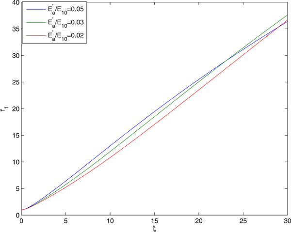
Figures 1, 2, 3 illustrate the effect of the intensity of first beam (ignitor beam) on the evolution of the spot size of the laser beams with distance of propagation. The plots in Figure 1 depict that as the ignitor beam propagates through the air its spot size increases monotonically. This is due to the fact that nonlinear refraction of the ignitor beam favors the natural diffraction due to ionization induced defocusing. It is also observed that with increase in the intensity of ignitor beam the rate of its defocusing decreases. This is due to the fact that increase in the intensity of ignitor beam leads to decrease in its nonlinear refraction.
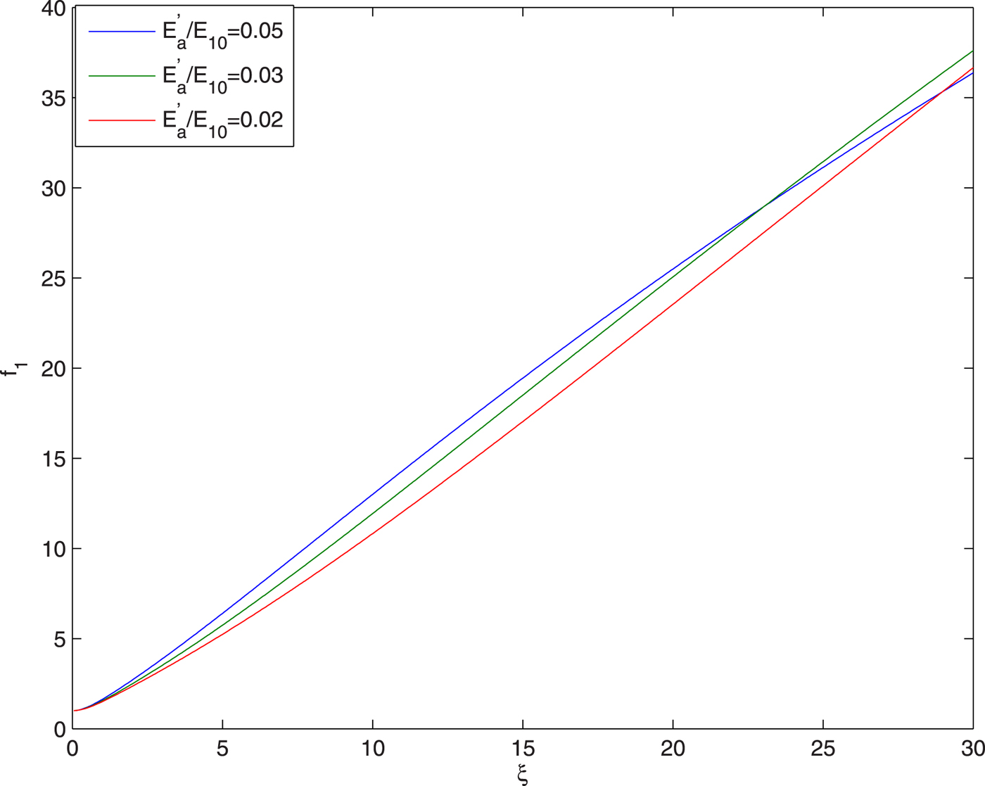
Fig. 1. Evolution of spot size of ignitor beam with distance of propagation at different intensities of ignitor beam viz.  ${E}^{\prime}_a/E_{10} = 0.05,0.03,0.02$ and at fixed values of
  ${\rm \beta} _2E_{20}^2 = 2.5$,
  ${\rm \beta} _3E_{30}^2 = 3$ and q = 3.
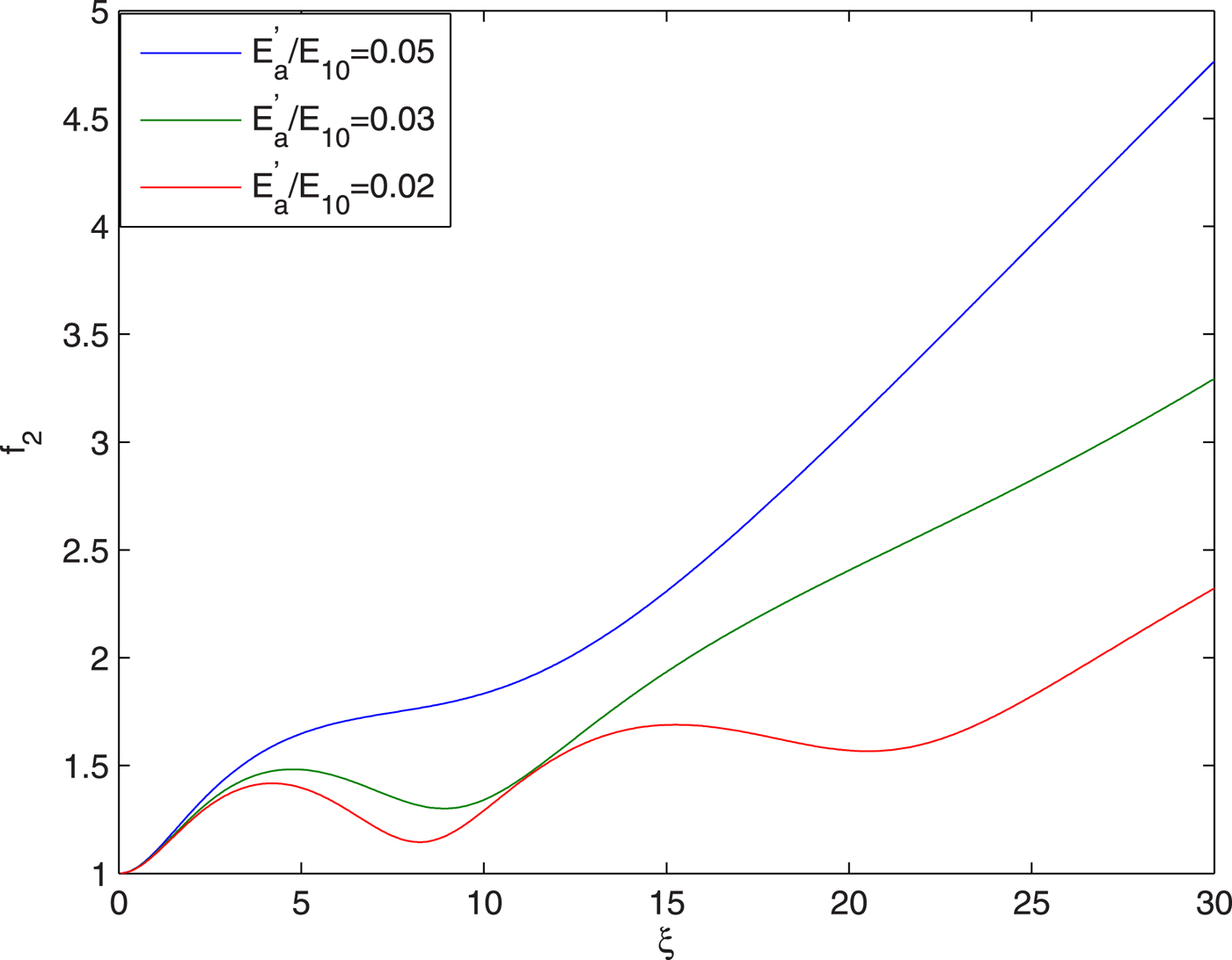
Fig. 2. Evolution of spot size of heater beam with distance of propagation at different intensities of ignitor beam viz.  ${E}^{\prime}_a/E_{10} = 0.05,0.03,0.02$ and at fixed values of
  ${\rm \beta} _2E_{20}^2 = 2.5$,
  ${\rm \beta} _3E_{30}^2 = 3$ and q = 3.
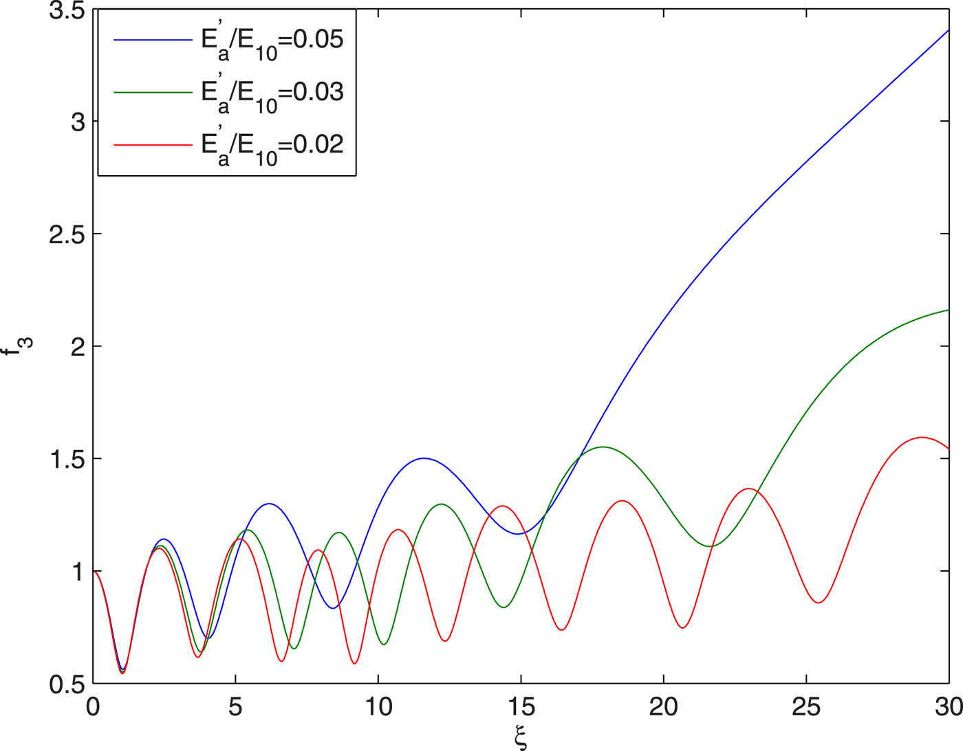
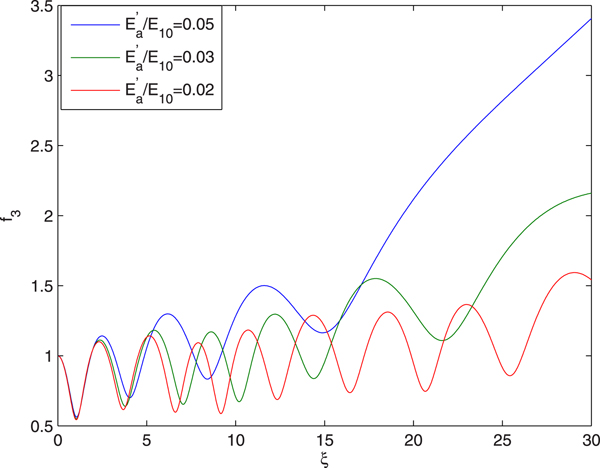
Fig. 3. Evolution of spot size of guided beam with distance of propagation at different intensities of ignitor beam viz.  ${E}^{\prime}_a/E_{10} = 0.05,0.03,0.02$ and at fixed values of
  ${\rm \beta} _2E_{20}^2 = 2.5$,
  ${\rm \beta} _3E_{30}^2 = 3$ and q = 3.
The plots in Figure 2 depict that as second beam (heater beam) propagates through the plasma, initially its spot size shows oscillatory focusing and then its spot size starts increasing monotonically. This is due to the fact that the plasma is being created by the ignitor beam. Initially, it is intense enough to create sufficient ionization of the air so that the plasma density is enough for the self-focusing of the heater beam. But as the ignitor beam gets defocused with distance of propagation, its intensity goes on decreasing and hence the plasma density becomes less than that required for the self-focusing of the heater beam.
It is also observed that with increase in the intensity of ignitor beam, the rate of defocusing of the heater beam decreases. This is due to the fact that with increase in the intensity of ignitor beam, the magnitude of refractive term opposing the diffractive term in Eq. (33) increases that leads to decrease in the rate of defocusing of the heater beam.
The plots in Figure 3 depict that as the third laser beam propagates through the plasma channel its beam width oscillates periodically, but after every focal spot the maxima and minima of the spot size shifts upwards. This is due to the fact that as the intense q-Gaussian laser beam is shone into the plasma channel, due to the large amplitude of the electric filed associated with the laser beam, the quiver velocity of the plasma electrons becomes comparable to that of light in vacuum. As a result of this, the mass of plasma electrons increases and hence the plasma frequency reduces. At the beam center, where the intensity is maximum, the mass of electrons is maximum and hence the plasma frequency is minimum. As a result of this, the central part of the wavefront of the laser beam experiences maximum refractive index due to which the wavefronts of the laser beam bend inwards resulting in self-focusing of the laser beam. As the laser beam gets self-focused with distance of propagation, its spot size r 0f 3 decreases which leads to increase in diffraction opposing the nonlinear refraction. This slows down focusing till minimum of f 3 is obtained. The diffraction effects then become dominant but not sufficient to overcome self-focusing. The process goes on till diffraction effect overpower the nonlinear refraction of the laser beam. These processes go on repeating themselves leading to oscillatory focusing/defocusing of the laser beam. The spot size of the laser beam thus oscillates or scallop periodically in sausage like fashion as the laser beam propagates down the channel.
Upward shifting of the minima of f 3 with distance of propagation is due to the decreasing plasma density resulting from the diffraction of the ignitor beam.
It is also observed that with increase in the intensity of the ignitor beam there is a significant increase in the effective distance of propagation of the third laser beam through the plasma channel. The underlying physics behind this fact is that with increase in the intensity of the ignitor beam there is decrease in the diffraction of heater beam that creates the channel. This leads to enhanced radial inhomogeneity in the refractive properties of the plasma channel resulting in enhanced propagation of the third beam through the plasma channel.
Figure 4 illustrates the effect of the intensity of ignitor beam on evolution of conversion efficiency Y 2 of second harmonics with distance of propagation. It has been observed that the conversion efficiency of the second harmonics is maximum at the focal spots of the guided beam. This is due to the fact that the focal spots of the laser beam are the regions of maximum intensity. Hence the amplitude of the generated plasma wave is maximum there resulting in maximum conversion efficiency of the second harmonics. It is also observed that increase in the intensity of the ignitor beam leads to increase in the conversion efficiency of the second harmonics. This is due to the fact that there is one to one correspondence between the extent of the self-focusing of guided beam and conversion efficiency of its second harmonics. As there is increase in the extent of self-focusing of guided beam with increase in the intensity of ignitor beam, there is increase in conversion efficiency of second harmonics with increase in the intensity of ignitor beam.
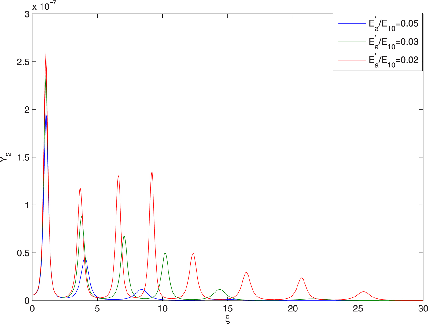
Fig. 4. Evolution of harmonic yield Y 2 of guided beam with distance
of propagation at different intensities of ignitor beam viz.  ${E}^{\prime}_a/E_{10} = 0.05,0.03,0.02$ and at fixed values of
  ${\rm \beta} _2E_{20}^2 = 2.5$,
  ${\rm \beta} _3E_{30}^2 = 3$ and q = 3.
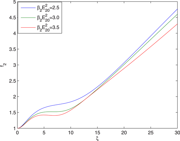
Figures 5 and 6 illustrate the effect of intensity of the heater beam on evolution of the spot size of second and third laser beam with distance of propagation. The plots in Figure 5 depict that with increase in the intensity of heater beam there is decrease in the rate of its defocusing. This is due to the fact that increase in the intensity of heater beam leads to enhanced heating of the plasma resulting in decrease in the rate of defocusing of the heater beam.
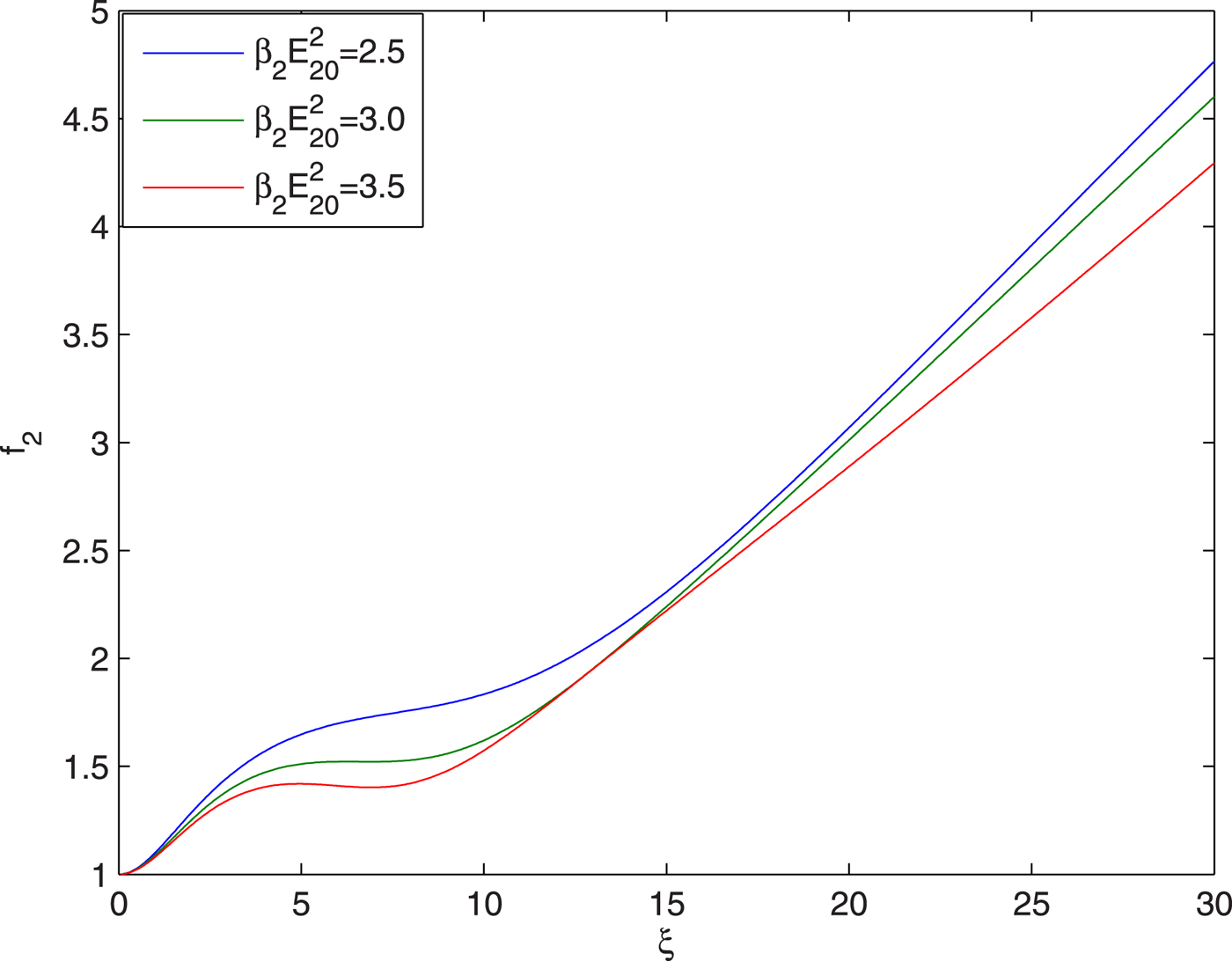
Fig. 5. Evolution of spot size of heater beam with distance of propagation at different intensities of heater beam viz.  ${\rm \beta} _2E_{20}^2 = 2.5,3,3.5$ and at fixed values of
  ${E}^{\prime}_a/E_{10} = 0.05$,
  ${\rm \beta} _3E_{30}^2 = 3$ and q = 3.
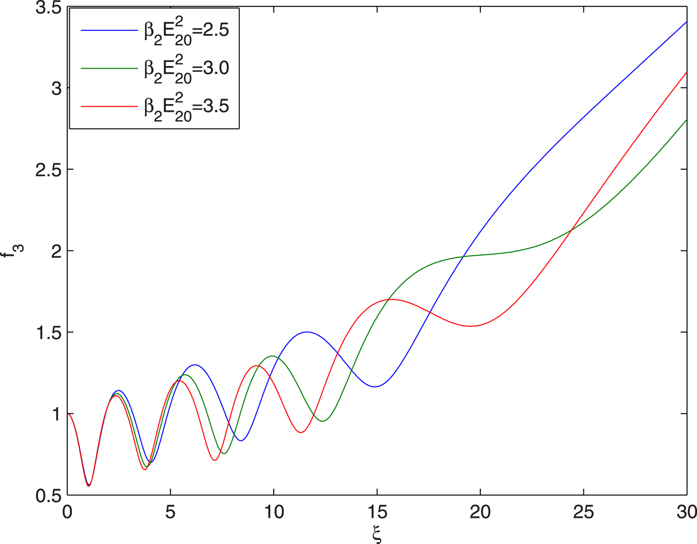
Fig. 6. Evolution of spot size of guided beam with distance of propagation at different intensities of heater beam viz.  ${\rm \beta} _2E_{20}^2 = 2.5,3,3.5$ and at fixed values of
  ${E}^{\prime}_a/E_{10} = 0.05$,
  ${\rm \beta} _3E_{30}^2 = 3$ and q = 3.
The plots in Figure 6 depict that increase in the intensity of heater beam enhances the effective distance of propagation of third beam through the plasma channel. This is due to the enhancement of the radial inhomogeneity in the refractive properties of the plasma channel with increase in the intensity of the heater beam.
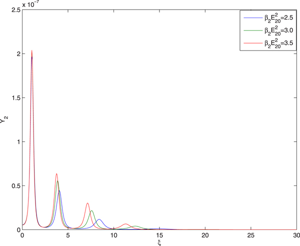
The plots in Figure 7 illustrate the effect of intensity of heater beam on the evolution of conversion efficiency of second harmonics of the guided beam. It has been observed that with increase in the intensity of heater beam there is increase in the conversion efficiency of second harmonics of guided beam. This is due to the fact that with increase in the intensity of heater beam there is increase in the extent of self-focusing of guided beam.
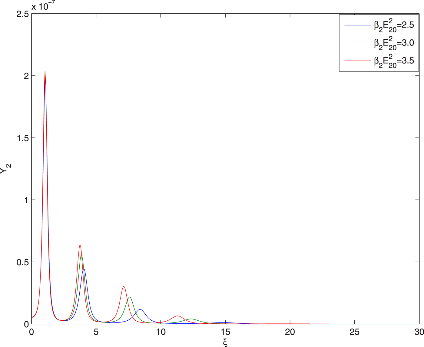
Fig. 7. Evolution of second harmonic yield Y 2 of guided beam with distance of propagation at different intensities of heater beam viz.  ${\rm \beta} _2E_{20}^2 = 2.5,3,3.5$ and at fixed values of
  ${E}^{\prime}_a/E_{10} = 0.05$,
  ${\rm \beta} _3E_{30}^2 = 3$ and q = 3.
Figure 8 illustrates the effect of intensity of the third beam on evolution of its spot size with distance of propagation. It is observed that increase in the intensity of the third beam leads to increase in its effective distance of propagation through the plasma channel. It is due to increase in the relativistic nonlinearity in the electron mass with increase in intensity of third beam.
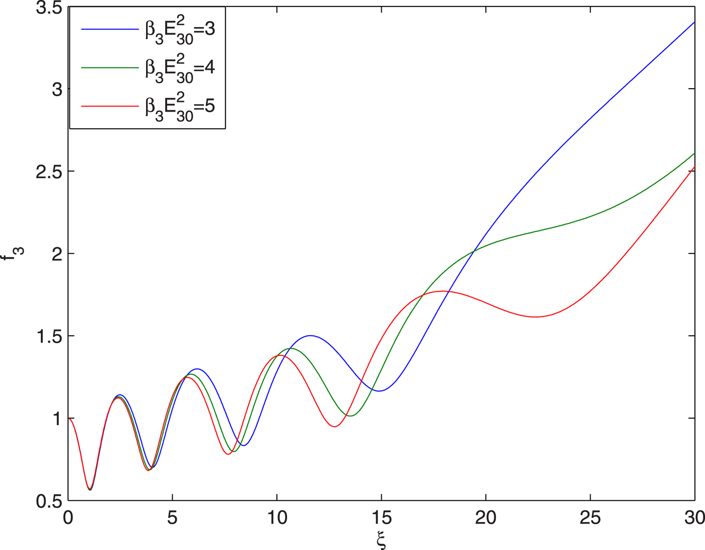
Fig. 8. Evolution of spot size of guided beam with distance of propagation at different intensities viz.  ${\rm \beta} _3E_{30}^2 = 3,4,5$ and at fixed values of
  ${E}^{\prime}_a/E_{10} = 0.05$,
  ${\rm \beta} _2E_{20}^2 = 2.5$ and q = 3.
The plots in Figure 9 illustrate the effect of intensity of third beam on the evolution of conversion efficiency of its second harmonics. It has been observed that with increase in the intensity of third beam there is increase in the conversion efficiency ofits second harmonics. This is due to the fact that with increase in the intensity of third beam there is increase in the extent of its self-focusing.
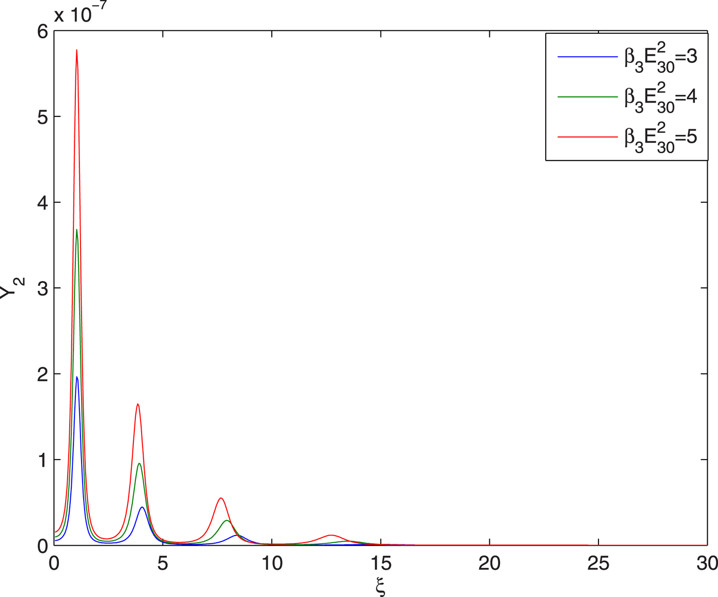
Fig. 9. Evolution of second harmonic yield Y 2 of guided beam with distance of propagation at different intensities viz.  ${\rm \beta} _3E_{30}^2 = 3,4,5$ and at fixed values of
  ${E}^{\prime}_a/E_{10} = 0.05$,
  $a_2E_{20}^2 = 2.5$ and q = 3.
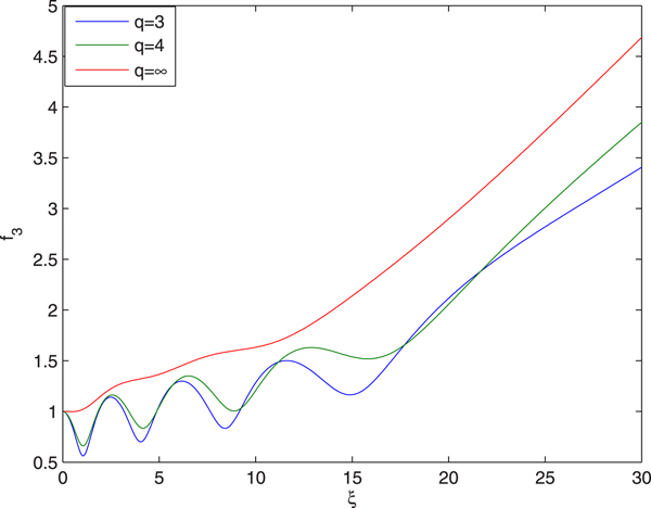
Figure 10 illustrates the effect of deviation of intensity profile (i.e., the effect of q) of the third beam from Gaussian profile, on the evolution of its spot size with distance of propagation. It is observed that with increase in the value of q there is decrease in the effective distance of propagation of third beam through the plasma channel. This is due to the fact that with increase in the value of q, the intensity of the laser beam converges towards the axial region of the wavefront. Hence, laser beams with higher values of q possess smaller root mean square radius. Also, it is well-known fact that the diffraction divergence of the laser beam is inversely proportional to its beam width. Hence, with increase in the value of q, the magnitude ofdiffractive term in Eq. (34) increases. Also, with increase in the value of q, the magnitude of nonlinear refractive term decreases due to the weakening of the axial part of the wavefront of the laser beam. As a result of this, the increase in the value of q leads to decrease in the effective distance of propagation of the third laser beam through the plasma channel.
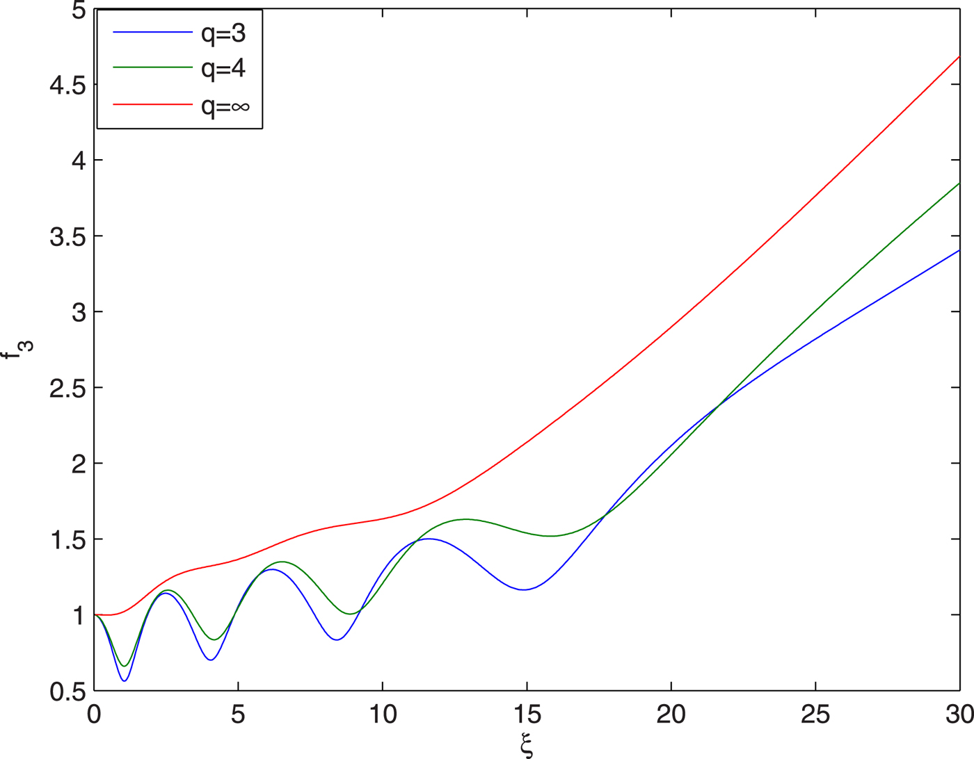
Fig. 10. Evolution of spot size of guided beam with distance of propagation at different values of q viz. q = 3, 4, ∞ and at fixed values of  $E_{10}/{E}^{\prime}_a = 0.05$,
  ${\rm \beta} _2E_{20}^2 = 2.5$ and
  ${\rm \beta} _3E_{30}^2 = 3$.
Figure 11 depicts the effect of q value of guided beam on conversion efficiency of its second harmonics. It has been observed that with increase in the value of q there is decrease in the conversion efficiency of the second harmonics. This is due to the reduced focusing of the guided beam with increase in the value of q.
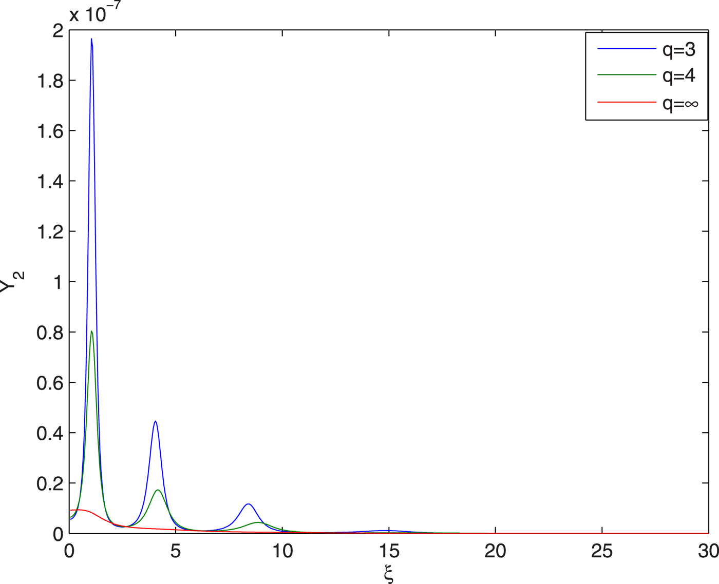
Fig. 11. Evolution of second harmonic yield Y 2 of guided beam with distance of propagation at different values of q viz. q = 3, 4, ∞ and at fixed values of  $E_{10}/{E}^{\prime}_a = 0.05$,
  ${\rm \beta} _2E_{20}^2 = 2.5$ and
  ${\rm \beta} _3E_{30}^2 = 3$.