


Introduction
Inertial confinement fusion (ICF) is an ongoing activity aiming for ignition of small pellets of thermonuclear, deuterium–tritium (DT) fuel by high-power lasers. The main direction of activity aims for strong compression of the fuel, where the resulting adiabatic heating would ignite the fuel. The pulse and the compression should be large and strong enough to keep the compressed fuel together for sufficient time for ignition, due to the inertia of the compressed pellet. This is the aim of both the direct drive (Nora et al., Reference Nora, Theobald, Betti, Marshall, Michel, Seka, Yaakobi, Lafon, Stoeckl, Delettrez, Solodov, Casner, Reverdin, Ribeyre, Vallet, Peebles, Beg and Wei2015) and indirect drive experiments (Betti and Hurricane, Reference Betti and Hurricane2016). In the present work, we present a patented idea on how to achieve final simultaneous volume ignition in the majority of the target based on recent theoretical and experimental achievements in relativistic fluid dynamics (RFD). (Csernai et al., Reference Csernai, Kroo and Papp2017).
In the pellet, the fusion reaction,  $D + T \to n(14.1\,{\rm MeV}) + {\kern 1pt} ^4{\rm He}(3.5\,{\rm MeV})$, takes place at a temperature of
  $kT \approx 10{\kern 1pt} \,{\rm keV}$. The produced 4He (or α) particles are then deposited in the hot DT plasma and heat it further. This is the plasma self-heating (or α-heating). The compression wave penetrates into the plasma with the speed of sound or with the speed of a compression shock. There are several facilities with different configurations attempting to achieve nuclear fusion this way. A comprehensive summary of these is presented in Betti and Hurricane (Reference Betti and Hurricane2016). The goal of these experiments is to generate and sustain a self-propagating burn wave, which reaches the whole interior of the pellet.
The up to now most successful indirect drive configuration at the National Ignition Facility (NIF) the target capsule is indirectly ignited by the thermal radiation coming from the gold hohlraum. The hohlraum is heated by the radiation of 192 laser beams (Betti and Hurricane, Reference Betti and Hurricane2016). In the middle of the hohlraum, a spherical pellet of DT fuel of initial outer radius of 1143μ µm is compressed and heated by the radiation. The pellet has a hole in the middle and a thin “ablator” layer, to reach better compression (Lindl, Reference Lindl1998; Lindl et al., Reference Lindl, Amendt, Berger, Glendinning, Glenzer, Haan, Kauffman, Landen and Suter2004; Haan et al., Reference Haan, Lindl, Callahan, Clark, Salmonson, Hammel, Atherton, Cook, Edwards, Glenzer, Hamza, Hatchett, Herrmann, Hinkel, Ho, Huang, Jones, Kline, Kyrala, Landen, MacGowan, Marinak, Meyerhofer, Milovich, Moreno, Moses, Munro, Nikroo, Olson, Peterson, Pollaine, Ralph, Robey, Spears, Springer, Suter, Thomas, Town, Vesey, Weber, Wilkens and Wilson2011; Robey et al., Reference Robey, Boehly, Celliers, Eggert, Hicks, Smith, Collins, Bowers, Krauter, Datte, Munro, Milovich, Jones, Michel, Thomas, Olson, Pollaine, Town, Haan, Callahan, Clark, Edwards, Kline, Dixit, Schneider, Dewald, Widmann, Moody, Doppner, Radousky, Throop, Kalantar, DiNicola, Nikroo, Hamza, Horner, Bhandarkar, Dzenitis, Alger, Giraldez, Castro, Moreno, Haynam, LaFortune, Widmayer, Shaw, Jancaitis, Parham, Holunga, Walters, Haid, Mapoles, Sater, Gibson, Malsbury, Fair, Trummer, Coffee, Burr, Berzins, Choate, Brereton, Azevedo, Chandrasekaran, Eder, Masters, Fisher, Sterne, Young, Landen, Van Wonterghem, MacGowan, Atherton, Lindl, Meyerhofer and Moses2012). The incoming and reflected light exercised a pressure and compressed the pellet at NIF, to about R = 50 − 80 μm just before ignition. At this moment the hole in the capsule is already filled in, and the target density was compressed to about 300–700 g/cm3, (Clark et al., Reference Clark, Marinak, Weber, Eder, Haan, Hammel, Hinkel, Jones, Milovich, Patel, Robey, Salmonson, Sepke and Thomas2015; Reis et al., Reference Reis, Hanrahan and Levedahl2016). In some cases, especially at the earlier “low foot” initial irradiation, this target showed the development of Rayleigh–Taylor (RT) instabilities, which reduced the efficiency of ignition. Recent simulations suggest that low foot performance was dominated by ablation front instability growth, high foot implosions appear to be dominated by hohlraum flux asymmetries (Clark et al., Reference Clark, Weber, Milovich, Salmonson, Kritcher, Haan, Hammel, Hinkel, Hurricane, Jones, Marinak, Patel, Robey, Sepke and Edwards2016).
At NIF the initial compression pulse, the “foot” had a lower frequency or longer wavelength of 100–350 nm, and led to lower temperature irradiation in the hohlraum of T RAD = 270 − 300 eV (Glenzer et al., Reference Glenzer2011). This had a higher reflectivity on the target, and led to compression. The reflectivity of light is high (>0.6) for lower energy irradiation and decreasing with increasing energies. It becomes negligible at  $\hbar\! {\rm \omega} = 1{\kern 1pt} \,{\rm keV}$. The compression pulse was followed by a shorter, higher frequency ignition pulse. The higher frequency pulse has negligible reflectivity and decreasing absorptivity, having
  $\alpha _K = 10^6{\kern 1pt} {\rm c}{\rm m}^{ - 1}$ at
  $\hbar\! \omega = 20\,{\rm eV}$ and
  $\alpha _K = 10\,{\kern 1pt} {\rm c}{\rm m}^{ - 1}$ at
  $\hbar\! \omega = 1{\kern 1pt} \,{\rm keV}$. If we take a higher frequency, shorter wavelength of 20 nm in the X-ray range then the absorptivity of the DT fuel is about
  $\alpha _K = 10^4{\kern 1pt} {\rm c}{\rm m}^{ - 1}$ (Hu et al., Reference Hu, Collins, Goncharov, Boehly, Epstein, McCrory and Skupsky2014). This means that the full pulse energy is absorbed in 10−4cm = 1 μm. That is in a thin surface layer. The internal domain is heated up due to adiabatic compression, up to ignition, but the major part of the approximately 10 μm thin compressed surface layer remains cold and only 1 µm is heated up at the outside surface. See Figure 8 of (Hu et al., Reference Hu, Collins, Goncharov, Boehly, Epstein, McCrory and Skupsky2014).
Compression shocks: The final stage of compression both in direct (Boehly et al., Reference Boehly, Goncharov, Seka, Barrios, Celliers, Hicks, Collins, Hu, Marozas and Meyerhofer2011) and indirect drive (Glenzer et al., Reference Glenzer2011) experiments was done by initiating 3–4 implosion shocks, well timed, so that all shocks converged to a final one with maximal speed. The fine timing of these shocks was based on the LASNEX and HYDRA non-RFD codes, which could describe “space-like” implosion shocks (i.e. shocks with space-like normal in the space–time). The final shock velocities reached 1 − 1.25 × 10⁻³ c in the National Ignition Champagne (Jones et al., Reference Jones, Cerjan, Marinak, Milovich, Robey, Springer, Benedetti, Bleuel, Bond, Bradley, Callahan, Caggiano, Celliers, Clark, Dixit, Doppner, Dylla-Spears, Dzentitis, Farley, Glenn, Glenzer, Haan, Haid, Haynam, Hicks, Kozioziemski, LaFortune, Landen, Mapoles, MacKinnon, McNaney, Meezan, Michel, Moody, Moran, Munro, Patel, Parham, Sater, Sepke, Spears, Town, Weber, Widmann, Widmayer, Williams, Atherton, Edwards, Lindl, MacGowan, Suter, Olson, Herrmann, Kline, Kyrala, Wilson, Frenje, Boehly, Glebov, Knauer, Nikroo, Wilkens and Kilkenny2012; Landen et al., Reference Landen, Benedetti, Bleuel, Boehly, Bradley, Caggiano, Callahan, Celliers, Cerjan, Clark, Collins, Dewald, Dixit, Doeppner, Edgell, Eggert, Farley, Frenje, Glebov, Glenn, Glenzer, Haan, Hamza, Hammel, Haynam, Hammer, Heeter, Herrmann, Hicks, Hinkel, Izumi, Gatu Johnson, Jones, Kalantar, Kauffman, Kilkenny, Kline, Knauer, Koch, Kyrala, LaFortune, Ma, Mackinnon, Macphee, Mapoles, Milovich, Moody, Meezan, Michel, Moore, Munro, Nikroo, Olson, Opachich, Pak, Parham, Patel, Park, Petrasso, Ralph, Regan, Remington, Rinderknecht, Robey, Rosen, Ross, Salmonson, Sangster, Schneider, Smalyuk, Spears, Springer, Suter, Thomas, Town, Weber, Wegner, Wilson, Widmann, Yeamans, Zylstra, Edwards, Lindl, Atherton, Hsing, MacGowan, Van Wonterghem and Moses2012; Robey et al., Reference Robey, Boehly, Celliers, Eggert, Hicks, Smith, Collins, Bowers, Krauter, Datte, Munro, Milovich, Jones, Michel, Thomas, Olson, Pollaine, Town, Haan, Callahan, Clark, Edwards, Kline, Dixit, Schneider, Dewald, Widmann, Moody, Doppner, Radousky, Throop, Kalantar, DiNicola, Nikroo, Hamza, Horner, Bhandarkar, Dzenitis, Alger, Giraldez, Castro, Moreno, Haynam, LaFortune, Widmayer, Shaw, Jancaitis, Parham, Holunga, Walters, Haid, Mapoles, Sater, Gibson, Malsbury, Fair, Trummer, Coffee, Burr, Berzins, Choate, Brereton, Azevedo, Chandrasekaran, Eder, Masters, Fisher, Sterne, Young, Landen, Van Wonterghem, MacGowan, Atherton, Lindl, Meyerhofer and Moses2012), while recently with the initial “high foot” irradiation (Clark et al., Reference Clark, Weber, Milovich, Salmonson, Kritcher, Haan, Hammel, Hinkel, Hurricane, Jones, Marinak, Patel, Robey, Sepke and Edwards2016) velocities reached 1.6 × 10⁻³c.
RFD: These velocities are significantly less than the speed of light, c, so why would we need RFD to describe these reactions? RFD must be used not only with high velocities or high-velocity gradients but also at (A) radiation dominated processes, that is at very high temperatures, where the energy density and the pressure are of the same order of magnitude and not dominated by the rest mass of the matter. RFD has qualitatively different features, proven theoretically and experimentally: Detonation or burning fronts can be both space- and time-like (i.e. simultaneous in space–time) (Csernai, Reference Csernai1987) and in (B) radiation dominated processes, fluctuations of the burning front are smoothed out because radiation will transfer energy to volume elements with smaller energy density, which were created by mechanical flow fluctuations (Zeldovich and Raiser, Reference Zeldovich and Raiser1966).
Considerations for the target
In the following analytic, scaling consideration we could take (a) a compressed initial state of radius R, which is then not compressed further much, but heated up with a short penetrating light pulse. Alternatively, we could (b) consider a solid sphere of the same amount of DT fuel, which is then made transparent and ignited by a laser pulse without significant compression. In this second case due to the smaller density, we will need a more energetic short pulse but also longer time because of the larger size.
Jarrott et al. (Reference Jarrott, Wei, McGuffey, Solodov, Theobald, Qiao, Stoeckl, Betti, Chen, Delettrez, Döppner, Giraldez, Glebov, Habara, Iwawaki, Key, Luo, Marshall, McLean, Mileham, Patel, Santos, Sawada, Stephens, Yabuuchi and Beg2016) used a similar size target in a direct drive configuration, with an outer ablator layer and initial compression. These experiments did not achieve ignition; however, they used a special cone-in-shell configuration of the target. Through doping the target with Cu, they were able to project the K-shell radiation of the target when it was radiated by an ultraviolet driver beam. From their images in Figure 2d, f of (Jarrott et al., Reference Jarrott, Wei, McGuffey, Solodov, Theobald, Qiao, Stoeckl, Betti, Chen, Delettrez, Döppner, Giraldez, Glebov, Habara, Iwawaki, Key, Luo, Marshall, McLean, Mileham, Patel, Santos, Sawada, Stephens, Yabuuchi and Beg2016), we see that ignition is achieved in an area of approximately 50 µm radius from the center of the target. By using a high-contrast laser and a 40 µm cone tip they were able to increase the fast electron coupling to the core from <5% to 10–15% by an increase in the core-density and decrease in the source-to-core distance. If this laser-to-electron conversion efficiency would be further increased, the total laser energy coupled to the core would also increase above 15%, which may be good if we want to achieve fast-ignition inertial-confinement fusion.
Here we consider another configuration, without ablator layer and without too much pre-compression, using the early examples in (Csernai, Reference Csernai1987; Csernai and Strottman, Reference Csernai and Strottman2015). These estimates are based on an analytic, scaling solution of relativistic radiation dominated fluid dynamics, which demonstrates the consequences of this approach. The model parameters are given in terms of the pre-compressed pellet radius R, and the light penetration time across this pellet. These can be rescaled to any actual pre-compressed pellet size and fuel density at this time. To keep the transparency of the simple analytic scaling solution we describe a solid target, without a hole in it. To have some approximate quantitative result, we chose a target about 640 µm radius, with a DT ice as fuel. The target density is taken to 1.062 g/cm3, assuming that this is a pre-compressed density, which can be achieved still without the occurrence of RT instability. This target a priory has smaller absorptivity. If we want to absorb the whole energy of the incoming laser light on ~1.3 mm length, we need an absorptivity of  $\alpha _K \approx 8{\kern 1pt} \,{\rm c}{\rm m}^{ - 1}$. This is about the absorptivity of DT fuel for soft X-ray radiation of 1 nm wavelength. See Figure 2 of (Hu et al., Reference Hu, Collins, Goncharov, Boehly, Epstein, McCrory and Skupsky2014). Longer wavelength radiation would have a larger absorptivity, and would be absorbed in the outside layers of the pellet.
Simplified model
Consider a spherical piece of matter (E), which is sufficiently transparent for radiation. The absorptivity of the target matter is considered to be constant, such that the total energy of the incoming light is observed fully when the light reaches the opposite edge of the spherical target. This matter undergoes an exothermic reaction if its temperature exceeds T c.
The target matter is surrounded by a set of spherically distributed laser beams, which emit the radiation necessary to heat up E. Here, for simplicity, we are neglecting the expansion of the outer shell inwards as well as the expansion of the core so that the core radius R is taken to be constant. We will measure the length in units of μm, and the time in units of μm/c.
We intend to calculate the temperature distribution, T(t, r), within the sphere, as a function of time, t, and the radial distance from the center of the sphere, that is radius r. We have two steps of the evaluation:
(i) In the first step, we calculate how much energy can reach a given point at r from the outside surface of the sphere. Here we have to take into account that the outside thermal radiation starts at time t = 0, so there is no radiation before. The eventual, “Low foot” type pre-compression is not included in this dynamical calculation. Furthermore, we must consider, which parts of the outside surface can reach a point inside the sphere at time t, and which are on the backward light-cone of the point at r and time t. The integral for the energy density reaching the point from this part of the two-dimensional outside surface of the sphere in unit time interval, dt, is dU(t, r)/dt.
(ii) Then we have to add up the accumulated radiation at position r, for the previously obtained energy and to obtain the time dependence of the temperature distribution, T(t, r), we have to integrate dU(t, r)/dt from t = 0, for each spatial position.
We perform the surface integral of step (i) in terms of integration for the proper time of the radiation with a delta function, selecting the surface element, which can reach the given internal point at a time.
Let us study a point within the sphere, at a distance r from the center. Choose the x-axis passing through this point and the center of the sphere. See Figure 1.
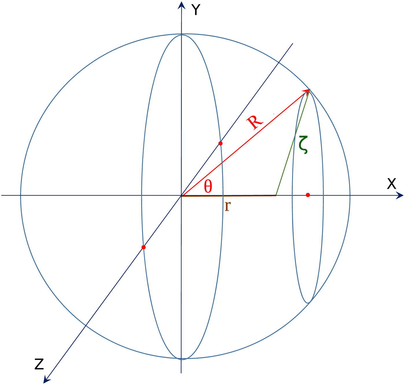
Fig. 1. The sphere of the fuel, with an internal point at the radius r. Let us chose the x-axis so that it passes through the point at r and the center of the sphere. Then let us chose a point on the sphere, and the angle of this point from the x-axis is denoted by Θ. Then the length between this surface point and the internal point at r is ζ = (R 2 + r 2 − 2Rr cosΘ)1/2. The propagation time from the surface point to the point at r equals τ = ζ/c.
The surface area of a ring of the sphere at the selected polar angle Θ is dS = 2πR 2sinΘ dθ.
Step (i): At a point at r we receive radiation from a layer edge ribbon at time τ. The radiation at distance ζ is decreasing as 1/ζ 2. The total radiation reaching point r from the ribbon at Θ is
 $${\rm d}U(t,r) \propto \displaystyle{1 \over {\zeta ^2}}\delta (\zeta - \sqrt {R^2 + r^2 - 2rR\cos \Theta} ),$$
where τ = ζ/c, and we should integrate this for the surface of all ribbons.
The average intensity of thermal radiation reaching the surface of the pellet amounts to Q per unit surface (μm2) and unit time (μm/c). Let us take a typical value for the energy of the total ignition pulse to be 2 MJ, in time 10 ps, then Q = 2MJ (4π)−1(0.640 μm)−2 (10 ps)−1 or Q ≈ 3.87 × 10²⁰, W/cm2 = 1.29 × 10¹⁰ Jc/cm3.
Up to a given time t, the light can reach a space–time point (t, r), inside the sphere from different points of the outside surface, which were emitted in different times. At early times it may be that none of the surface points are within the backward light-cone of the point (t, r). At later times, from part of the surface points the light can reach (t, r), while at times larger than 2R/c all internal points can be reached from any surface point of the sphere. Thus, we calculate first what energy density, U(t, r), we get at a space–time point (t, r), from earlier times. At a given point at R measured from the center of the sphere (assuming that a constant fraction, αK, of the radiation energy is absorbed in unit length):Footnote 1
 $$\eqalign{{\rm d}U(t,r) &= \alpha _KQ\int_0^t {\rm d}\tau 2\pi R^3 \cr & \quad \times \int_0^\pi {\rm d}\cos \Theta \displaystyle{{\delta (\zeta - \sqrt {R^2 + r^2 - 2rR\cos \Theta} )} \over {R^2 + r^2 - 2rR\cos \Theta}} \cr &= \alpha _KQ\int_0^t {\rm d}\tau 2\pi R^3\int_1^{ - 1} {\rm d}x\displaystyle{{\delta (\zeta - \sqrt {R^2 + r^2 - 2rRx} )} \over {R^2 + r^2 - 2rRx}} \cr &= 2\pi R^3\alpha _KQ \cdot (Rr)^{ - 1}\int_{(R - r)/c}^{aR/c} \displaystyle{{{\rm d}\tau} \over {\tau {\rm c}}},} $$
where the integral over dx gives  $1/(Rr\zeta ) = (R{\kern 1pt} r{\kern 1pt} \tau {\kern 1pt} c)^{ - 1}$. The time, dτ, integral runs from the nearest point of the backward light cone to the surface of the sphere to the furthest point, aR/c. Here the parameter a will be described later. See Figure 2.
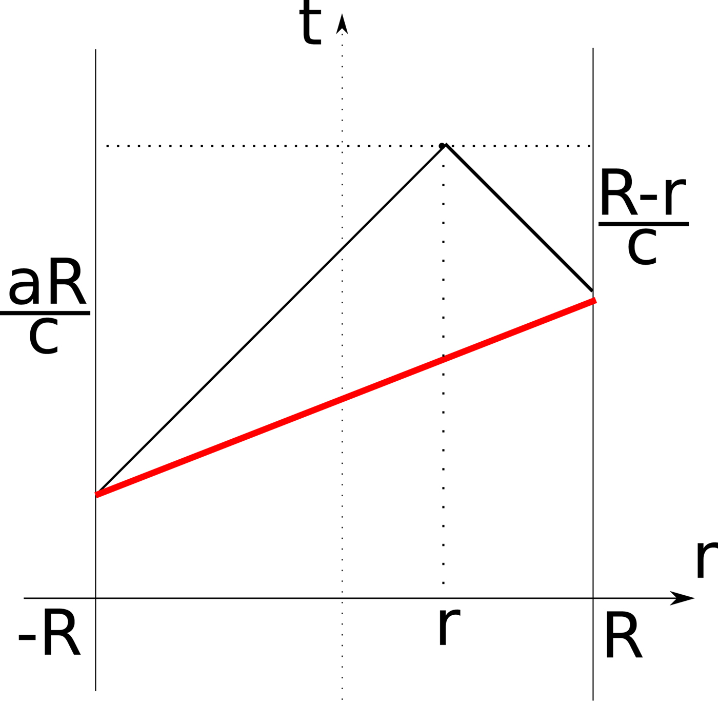
Fig. 2. The boundaries of the integration domains depending on r and t. The domain for the smallest τ –values cannot receive radiation, Eq. (2), because the radiation started at (R − r)/c earlier and it reaches the internal point at r later, At the same time, the radiation from the opposite side reaches the point r also in time aR/c. The contour of the intersection of the backward light-cone with the surface of the sphere is indicated with the thick, red line. When the time from the momentum of ignition is longer than t = 2R/c the radiation reaches the matter from all sides at every location r. At earlier times the upper boundary of integration should be evaluated. See Equation (4).
Now we introduce a new, dimensionless time variable: q ≡ τc/R. Thus,
 $$\eqalign{& {\rm d}U(t,r) = 2\pi R^3\alpha _KQ \cdot (rRc)^{ - 1} \cr & \quad \int_{1 - r/R}^a \displaystyle{{{\rm d}q} \over q} = 2\pi R^2\alpha _KQ \cdot (rc)^{ - 1}[\ln (q)]_{1 - r/R}^a,} $$
where ζ = τc and a is the upper boundary of the integral over the dimensionless time dq.
 $$a = \left\{ {\matrix{ {1 - r/R,} \hfill & {q \lt 1 - r/R} \hfill \cr {q,} \hfill & {1 - r/R \lt q \lt 1 + r/R} \hfill \cr {1 + r/R,} \hfill & {q \gt 1 + r/R.} \hfill \cr}} \right.$$
Here actually the integral over dq is adding up the contributions of those surface elements of the sphere, from where radiation reaches the internal point at r at the same dimensionless time q. In the first case, the radiation does not reach the point at r then, in the second part, the radiation from the closest point of the sphere reaches r but from the opposite point not yet, in the third case radiation reaches r from all sides.
Thus the energy deposited in unit time at a dimensionless time q is
 $$\eqalign{& {\rm d}U(r,q) = \displaystyle{{2\pi R^2\alpha _KQ} \over {rc}} \times \cr & \quad \quad \left\{ {\matrix{ {\ln [(1 + r/R)/(1 - r/R)],} \hfill & {q \gt 1 + r/R} \hfill \cr {\ln [q/(1 - r/R)],} \hfill & {1 - r/R \lt q \lt 1 + r/R} \hfill \cr {0,} \hfill & {q \lt 1 - r/R.} \hfill \cr}} \right.} $$
Step (ii): Neglecting the compression and assuming constant specific heat c v, we get that k BdT = 1/nc vdU · dq, where k B is the Boltzmann constant, and so
 $$\eqalign{k_{\rm B}T(t,r) = & \displaystyle{1 \over {nc_v}}\int_0^{t{\rm c}/R} {\rm d}q \cdot {\rm d}U(r,q) = \displaystyle{{2\pi R^2\alpha _KQ} \over {n{\kern 1pt} c_v{\kern 1pt} rc}} \cr & \times \left\{ {\matrix{ {\left[ {q{\kern 1pt} \ln \left( {1 + r/R)/(1 - r/R)} \right)} \right]_{1 + r/R}^{tc/R}} \hfill \cr { + (1 + r/R){\kern 1pt} \ln [(1 + r/R)/(1 - r/R)] - 2r/R{\kern 1pt},} \hfill \cr {\quad {\rm if:}\quad tc/R \gt 1 + r/R} \hfill \cr {\left[ {q{\kern 1pt} \ln \left( {q/(1 - r/R)} \right) - q} \right]_{1 - r/R}^{tc/R} {\kern 1pt},} \hfill \cr {\quad \quad {\rm if:}\quad 1 - r/R \lt tc/R \lt 1 + r/R} \hfill \cr {0,\quad {\rm if:}\quad tc/R \lt 1 - r/R} \hfill \cr}} \right.} $$
and so,
 $$\eqalign{& k_{\rm B}{\kern 1pt} T(t,r) = H \cdot \displaystyle{{R^2} \over r} \times \cr & \quad \left\{ {\matrix{ {tc/R{\kern 1pt} \ln [(1 + r/R)/(1 - r/R)] - 2r/R{\kern 1pt},} \hfill \cr {\quad {\rm if:}\quad tc/R \gt 1 + r/R} \hfill \cr {tc/R{\kern 1pt} \ln [tc/(R/(1 - r/R))] - tc/R + 1 - r/R,} \hfill \cr {\quad {\rm if:}\quad 1 - r/R \lt tc/R \lt 1 + r/R} \hfill \cr {0,\quad {\rm if:}\quad tc/R \lt 1 - r/R,} \hfill \cr}} \right.} $$
where the number density of uncompressed DT ice is  $n = 3.045 \times 10^{22}{\kern 1pt} {\rm c}{\rm m}^{ - 3}$, and the leading constant, H, is
 $$H \equiv \displaystyle{{2\pi Q} \over {c{\kern 1pt} c_V}}{\kern 1pt} \displaystyle{{\alpha _K(r)} \over n} = 8.54 \times 10^{ - 12}{\rm J/cm}.$$
If the absorptivity is varying, αK = αK(r), then it follows:
 $$k_{\rm B}T(t,r) = \displaystyle{{2\pi QR} \over {c{\kern 1pt} c_V{\kern 1pt} n}}\left\{ {\matrix{ {0,\quad {\rm if:}\quad tc \lt R - r} \hfill \cr {\displaystyle{{\alpha _K(r)tc} \over r}\left( {\ln \displaystyle{{tc} \over {R - r}} - 1} \right) + \displaystyle{{R - r} \over r},} \hfill \cr {\quad {\rm if:}\quad R - r \lt tc \lt R + r} \hfill \cr {\displaystyle{{\alpha _K(r)tc} \over r}\ln \displaystyle{{R + r} \over {R - r}} - 2\;,} \hfill \cr {\quad {\rm if:}\quad tc \gt R + r.} \hfill \cr}} \right.$$
The surface of the discontinuity is characterized by the T(t, r) = T c contour line. If T c is the ignition temperature, then here the DT ignition takes place on this contour line in the space–time. The tangent of this line is if tc > R + r:
 $$\eqalign{& \left( {\displaystyle{{\partial r} \over {c\partial t}}} \right)_{T_{\rm c}} = \left( {\displaystyle{{\partial T} \over {c\partial t}}} \right)_{T_{\rm c}}/\left( {\displaystyle{{\partial T} \over {\partial r}}} \right)_{T_{\rm c}} = \cr & \quad \ln \displaystyle{{{{R + r} / {R - r}}} \over \matrix{\left\{ {tc\left( {{{2R} / {R^2 - r^2}}} \right) + \left[ {\left( {{{{{\alpha} ^{\prime}}_{\!K}(r)} / {\alpha _K(r)}}} \right) - \left( {{1 / r}} \right)} \right]} \right. \hfill \cr \quad \left. {\ln \left( {{{R + r} / {R - r}}} \right)} \right\} \hfill}}.} $$
So the point (t c, r c) where the space- and time-like parts of the surface meet, from  $(\partial r/(c\partial t))_{T_{\rm c}} = 1$ is
 $$t_{\rm c} = \left\{ {\displaystyle{{2cR} \over {R^2 - r_{\rm c}^2}} {\left[ {\ln \displaystyle{{R + r_{\rm c}} \over {R - r_{\rm c}}}} \right]}^{ - 1} + \left( {\displaystyle{{{{\alpha} ^{\prime}}_K(r)} \over {\alpha _K(r)}} - \displaystyle{c \over {r_{\rm c}}}} \right)} \right\}^{ - 1}.$$
This line t = t c(r c) separates the space- and time-like branch of the discontinuity of T(t, r) = T c.
The discontinuity initiates at r = R and t = 0 and it propagates first slowly inwards. Due to the radiative heat transfer the contour line of ignition, T(t, r) = T c, accelerates inwards, and at r c = r c(T c) it develops smoothly from space-like into a time-like discontinuity.
The same type of gradual development from space-like into time-like detonation (A) occurs in the last, hadronization, phase of ultra-relativistic heavy ion collisions (Csernai, Reference Csernai1994; Heinz and Kolb, Reference Heinz and Kolb2002; Chatterjee et al., Reference Chatterjee, Frodermann, Heinz and Srivastava2006; Frodermann et al., Reference Frodermann, Chatterjee and Heinz2007; Molnar et al., Reference Molnar, Molnar, Csernai, Magas, Lazar, Nyiri and Tamosiunas2007; Csernai et al., Reference Csernai, Cheng, Horvat, Magas, Strottman and Zétényi2009; Armesto et al., Reference Armesto, Dainese, d'Enterria, Masciocchi, Roland, Salgado, van Leeuwen and Wiedemann2014; Floerchinger and Wiedemann, Reference Floerchinger and Wiedemann2014). If we include radiative heat transfer in these scenarios, the transition from space- to time-like deflagration will be gradual. This, however, requires more involved numerical calculations.
In Figure 3, we see the constant temperature contour lines, T(t, r) = const., in the space–time, from the analytical solution. For the first or second T = const. contour line the time-like detonation region extends from the center of the pellet to the half of radius R. This is only about 12% of the volume, so the time-like detonation, in itself, cannot achieve total simultaneous volume ignition, and in the outside region instabilities might develop!

Fig. 3. Analytic solution of the radiation dominated implosion model of rapid ignition. The temperature distribution in function of distance and time. The lower boundary and the dotted line represent the light cones from the left and right edge of the pellet, initiated at t = 0. The absorptivity of the pellet is  $\alpha _K = 8{\kern 1pt} \,{\rm c}{\rm m}^{ - 1}$. The temperature is measured in units of T 1 = H · R = 21.3 keV, and T n = n · T 1.
Variable absorptivity
In order to study the effect of variable absorptivity, we reformulated the numerical model to perform all integrals of the model numerically. This will enable us to study the configuration where the pellet is manufactured with nano-shells inside, which regulate the absorptivity of the DT ice pellet.
At first, we still assumed constant absorptivity with the same value  $\alpha _K = 8{\kern 1pt} \,{\rm c}{\rm m}^{ - 1}$. In Figure 4, the numerical solution gives a qualitatively identical result, but at small radii, the numerical uncertainty leads to visible fluctuations and somewhat smaller central temperature increase. The domain of time-like, that is simultaneous ignition takes place in the central part of the pellet up to a radius of
  $r = 370{\kern 1pt} \,{\rm \mu m}$.

Fig. 4. Numerical solution of the radiation dominated implosion model of rapid ignition. The temperature distribution in function of distance and time. The dotted line represents the light cone. The absorption coefficient is constant  $\alpha _K = 8{\kern 1pt} \,{\rm c}{\rm m}^{ - 1}$. The decrease of radiation flux due to the absorption is neglected. The temperature is measured in units of T 1 = H · R = 21.3 keV, and T n = n · T 1. The finite numerical resolution leads to the fluctuations near r = 0. The color code for the temperature, T(t, r), is given in units of (MeV).
In Hu et al. (Reference Hu, Collins, Goncharov, Boehly, Epstein, McCrory and Skupsky2014), Rochester and NIF experimental data were studied and analyzed with opacity data, extracted both from basic principles and from comparison with ICF experiments. The absorption coefficient αK (cm–1), defined by  $I(x) = \exp ( - \alpha _k{\kern 1pt} x)I_0$, and the Rosseland and Planck opacities, K R defined by
  $I(x) = \exp ( - \alpha _{K_{\rm R}}{\kern 1pt} \rho {\kern 1pt} x)I_0$, were estimated and used to simulate the space–time development of ICF direct ignition experiments.
In our previous calculations, we used the absorption coefficient αK (cm–1), and the approximation that the intensity of the incoming laser light flux is sufficiently large so that its decrease by the absorption is negligible.
With increased absorptivity, one could reach more rapid heating. The fusion reaction rate per unit volume and unit time is f = n Dn T〈σv〉, depends on the D and T densities, n Dn T, and the reactivity, 〈σv〉. Due to the fusion cross-section, the reactivity is increasing up to about  $T = 70\! -\!\! 100{\kern 1pt} \,{\rm keV}$, and then decreases again. Thus, we could aim for a heating up to this temperature, with smaller pre-compression.
Variation of absorptivity by Nanotechnology
Doping INF pellets with golden nano-shells enables us to achieve the desired variable absorptivity (Tanabe, Reference Tanabe2016). Nano-shells irradiated by laser light exhibit a resonant light absorption, which can increase the plasmon field-strength by up to a factor of 40–100 or more (Prodan et al., Reference Prodan, Radloff, Halas and Nordlander2003; Nordlander and Prodan Reference Nordlander and Prodan2004). At present experimentally realizable nano-shell sizes ranges for core sizes: 5–500 nm, and for shell thickness: 1–100 nm. In a fuel target prepared initially with implanted Au nano-shells, after pre-compression, we can have nano-shells of a radius ≈ 10 nm.
The resonant light frequency of the nano-shell can be tuned in a very wide range by changing the size and thickness of the nano-shell. If the core (r 1) versus the shell thickness, r 1/(r 2 − r 1) is changed from 2 to 800 the resonant wavelength changed from 0.5 to 10 × 103 nm (Loo et al., Reference Loo, Lin, Hirsch, Lee, Barton, Halas, West and Drezek2004). For our purposes of short wavelength, X-ray photons the smaller and relatively more thick nano-shells are relevant. An eventual pre-compression modifies the nano-shells in this direction.
At the resonant frequencies, the nano-shells are able to absorb resonantly a rather high portion of incoming light. We can define the absorption, scattering, and extinction efficiencies, Q abs, Q sca, and Q ext, respectively (Lee and El-Sayed, Reference Lee and El-Sayed2005), where these coefficients, Q i, describe how much part of the energy of the incoming light is absorbed or scattered by the nano-shell, compared with its geometrical cross-section, G, that is for a sphere of radius  $R,G = R^2{\kern 1pt} \pi $.
The nano-shells can be tuned to either larger absorption efficiency or larger scattering efficiency. For our purposes, the larger absorption efficiency is optimal. The resonance extinction or absorption efficiency can reach a factor 10 or even more (Alam and Massoud, Reference Alam and Massoud2006).
Thus, the absorptivity of the target material of the pellet can be regulated by the density of implanted nano-shells. The target DT fuel has a bulk absorption coefficient, αk0 (cm–1). If we implant nano-shells with cross-section G = R 2π, with a density ρ (cm–3) then the absorptivity will increase to
 $$\alpha _k = \alpha _{k0} + \alpha _{{\rm ns}}\;,$$
where the absorptivity of nano-shells, αns, is
 $$\alpha _{{\rm ns}} = \rho GQ_{{\rm abs}}.$$
For a nano-shell of R = 30 nm the additional contribution would be ρGQ abs = ρQ abs 0.283 cm2. Consequently, for a typical nano-shell density (James et al., Reference James, Hirsch, West, O'Neal and Payne2007) of ρ = 1011/cm3 and a Q abs ≈ 10, we can reach an additional absorptivity of
 $$\alpha _{{\rm ns}} = 28.3\,{\rm c}{\rm m}^{ - 1}.$$
Higher nano-shell density and higher absorption efficiency can also be achieved. A pre-compression of the target fuel would further increase the absorptivity.
Absorption for DT densities in the range of  ${\rm \rho} = 5 - 200{\kern 1pt} {\rm g}/{\rm c}{\rm m}^3,T \approx 10^5{\kern 1pt} K$ were obtained in the range of
 $$\alpha _{k0} = 10^{ - 1} - 10\;{\rm c}{\rm m}^{ - 1}$$
as the light frequency increased to  $\hbar\! \omega = 1 - 10\,{\rm keV}{\rm.} $ That is the typical light mean free path was about 1 − 104 μm. Thus, while for low-frequency radiation,
  $\hbar\! \omega = 1 - 100{\kern 1pt} \,{\rm eV}$ the DT target is quite opaque, at higher frequencies or energy it is much more transparent. This leads to the result that the initial lower energy pulse leads primarily to compression. This effect is enhanced further with the application of the thin ablator sheet on the surface of the pellet (Benredjem et al., Reference Benredjem, Pain, Gilleron, Ferri and Calisti2014).
The additional opacity of nano-shells with typical nano-shell densities can increase the absorptivity by up to
 $$\alpha _{{\rm ns}} = 20 - 30\,{\rm c}{\rm m}^{ - 1},$$
which makes the fast ignition possibilities very versatile in this light frequency range. We can experiment with variable absorptivity, which is the normal high-temperature, high-frequency absorptivity of the DT fuel, αk0 ≈ 1 cm−1 at the outer edge of the pellet (i.e. at  $R = 640{\kern 1pt} \,{\rm \mu m}$) while in the center, it is αns = 20 − 30 cm−1 (i.e. about up to 30 times more). The space–time profile of the ignition will then depend on the radial profile of the increasing nano-shell doping toward the center of the pellet.
We could optimize this by achieving the largest simultaneous volume ignition domain, which eliminates the possibility of developing instabilities.
Here the question arises that under compression of a sample doped with nano-shells, how the doped particles will compress. The thickness and radius of the golden nano-shells are determined by the resonance condition of the laser irradiation. The stiffness of the shell interior can be chosen to keep the spherical shape of the nano-particles, the best choice can be cryogenic DT fluid. In a study of ICF capsules employing DT-wetted foam (Sacks and Darling, Reference Sacks and Darling1987) of similar size small pores, concluded that the inflight aspect ratio, hydrodynamic efficiency, and hot electron tolerance can be at least as good as for conventional DT targets. The compressed nano-shells will be resonant to higher laser frequencies, which can be taken into account, in the nano-shell fabrication.
Conclusions and discussions
Using nano-technology for ICF is mentioned recently (Kaymak et al., Reference Kaymak, Pukhov, Shlyaptsev and Rocca2016; Bargstenm et al., Reference Bargsten, Hollinger, Capeluto, Kaymak, Pukhov, Wang, Rockwood, YWang, Keiss, Tommasini, London, Park, Busquet, Klapisch, Shlyaptsev and Rocca2017). By placing aligned nano-rods or nano-wires on the surface of the pellet and irradiating it with femtosecond laser pulses of relativistic intensity, leads to a plasma with peak electron intensity and pressure. However, this pressure would lead to a pressure-driven adiabatic compression and heating, which can lead to RT instabilities, preventing simultaneous volume ignition.
In this model estimate, we have neglected the compression of the target solid fuel ball, as well as the reflectivity of the target matter. The relatively small absorptivity made it possible that the radiation could penetrate the whole target. With the model parameters, we used the characteristic temperature was T 1 = 21.3 keV, which is larger than the usually assumed ignition temperature, while our target is not compressed so the higher temperatures may be necessary to reach ignition according to the Lawson criterion. If we can achieve ignition at somewhat lower temperature than T 1, the ignition surface in the space–time includes a substantial time-like hyper-surface, where instabilities cannot develop because neighboring points are not causally connected.
From looking at the constant temperature contour lines in function of distance and time (Fig. 5), we see that the detonation at a higher critical temperatures T c ≈ T 4 − T 6 occurs when the radiation reaches the matter from the other side also at t c ≈ 1.5 ps. At these contour lines of  $T \approx 70 - 90{\kern 1pt} \,{\rm keV}$, about the interior 90% of the radius ignites at the same time (A), so the ignition is simultaneous for about 73% of the total volume. In this domain, no instabilities may occur.
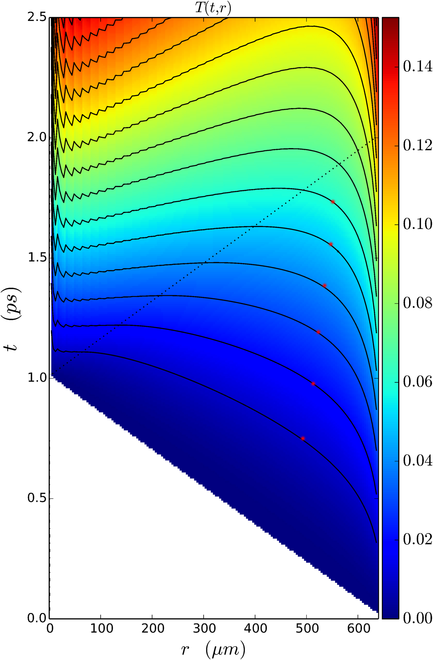
Fig. 5. Numerical solution of the radiation dominated implosion model of rapid ignition. The temperature distribution in function of distance and time. The dotted lines represent the light cone. The absorption coefficient is linearly changing with the radius. In the center, r = 0, αK = 30 cm−1 while at the outside edge  $\alpha _K = 8\,{\kern 1pt} {\rm c}{\rm m}^{ - 1}$. The decrease of radiation flux due to the absorption is neglected. The temperature is measured in units of T 1 = H · R = 21.3 keV, and the T n(r) = n · T 1 = const. contour lines are shown. The color code for the temperature, T(t, r), is given in units of (MeV). The finite numerical resolution leads to the fluctuations near r = 0, this is a numerical artifact. The stars on the temperature contour lines indicate the transition from the space-like front at the outside edge to the time-like front in the middle. The points of the middle part are not causally connected, so instabilities cannot develop.
We can also apply this model is to a pre-compressed, more dense target, which is transparent and has larger absorptivity. In this situation, the ignition temperature can be somewhat smaller, but we still can optimize the pulse strength and pulse length to achieve the fastest complete ignition of the target.
The above relatively short and very intensive irradiation is relevant for the absolute boundary of simultaneous, time-like ignition (A). With more detailed and quantitative estimate it is sufficient to require an irradiation intensity, which leads to a faster temperature increase towards T c than the growth rate of the RT instability or other instabilities. This can make even an order of magnitude increase in the critical irradiation time T c. Furthermore, if we also consider the smoothing effect of radiation dominated ignition front (B) then the critical irradiation time even longer. This could only be estimated with a 3 + 1D Computational RFD calculation.
We can see if we neglect the importance of the speed of light, the theory would be far-fetched from reality. It is important to use the proper relativistic treatment to optimize the fastest, more complete ignition, with the least possibility of instabilities, which reduce the efficiency of ignition.
Acknowledgements
Enlightening discussions with Igor Mishustin and Horst Stöcker are gratefully acknowledged. This work is supported in part by the Institute of Advance Studies, Köszeg, Hungary.


