1. INTRODUCTION
Indirect drive inertial confinement fusion (ICF) has received a great deal of attention in the last few decades as one of the most promising schemes to reach controlled fusion in the laboratory (Lindl et al., Reference Lindl, Amendt, Berger, Glendinning, Glenzer, Haan, Kauffman, Landen and Suter2004; Dewald et al., Reference Dewald, Glenzer, Landen, Suter, Jones, Schein, Froula, Divol, Campbell, Schneider, Holder, Wmcdonald, Niemann, Mackinnon and Hammel2005) and large laser facilities such as the National Ignition Facility (Haynam et al., Reference Haynam, Sacks, Wegner, Bowers, Dixit, Erbert, Heestand, Henesian, Hermann, Jancaitis, Manes, Marshall, Mehta, Menapace, Nostrand, Orth, Shaw, Sutton, Williams, Widmayer, White, Yang and Van Wonterghem2008), and laser megajoule project (Fleurot et al., Reference Fleurot, Cavailler and Bourgade2005) aim to reach breakeven using this scheme within the next few years. In the basic scheme, a microsphere of fuel (typically a mixture of deuterium and tritium) (Cook et al., Reference Cook, Kozioziemski, Nikroo, Wilkens, Bhandarkar, Forsman, Haan, Hoppe, Huang, Mapoles, Moody, Sater, Seugling, Stephens, Takagi and Xu2008; Chatain et al., Reference Chatain, Perin, Bonnay, Bouleau, Chichoux, Communal, Manzagol, Viargues, Brisset, Lamaison and Paquignon2008; Moreau et al., Reference Moreau, Levassort, Blondel, De Nonancourt, Croix, Thibonnet and Balland-Longeau2009) is placed inside a metallic cavity (hohlraum) and a large number of long and energetic laser pulses are focused onto the inner surface of the cavity. The X-rays generated by the interaction of the pulses with the metallic walls drive symmetrically (Seifter et al., Reference Seifter, Kyrala, Goldman, Hoffman, Kline and Batha2009) the compression of the fuel until sufficient pressure and temperature to initiate ignition are reached. The more relaxed uniformity and stability requirements are advantages of such a scheme compared to the direct drive approach (Canaud et al., Reference Canaud, Fortin, Garaude, Meyer and Philippe2004).
Many issues are however under the attention of the research community. Among these, the expansion through the hohlraum of the high-Z plasma resulting from the walls ablation is a concern, as this can perturb and degrade the uniformity of fuel compression; in fact, in vacuum hohlraums, the high-Z ablated plasma fills quickly the cavity, modifying the location and characteristics of laser absorption, and of the hot spots (Kauffman et al., Reference Kauffman, Powers, Dixit, Glendinning, Glenzer, Kirkwood, Landen, Macgowan, Moody, Orzechowski, Pennington, Stone, Suter, Turner, Weiland, Richard and Blain1998) long before the optimum black body temperature of the X-ray radiation is reached. Indeed, for large hohlraums and long pulses such as those required for ignition, the high-Z plasma dimensions can exceed several times the inverse bremsstrahlung absorption length of the laser light. In order to slow down the high-Z plasma expansion and reduce the detrimental effects on laser absorption and X-ray conversions, ignition target design for ICF implosions employs hohlraum's filled with a low-Z gas (typically He) or low density foams (Haan et al., Reference Haan, Herrmann, Salmonson, Amendt, Callahan, Dittrich, Edwards, Jones, Marinak, Munro, Pollaine, Spears and Suter2007). The gas fill also minimizes the possibility of plasma jets originating from the localized laser spot regions hitting the capsule.
Plasma filling of the hohlraum and the specific details of the laser energy deposition create a complex environment, which is difficult to model in a satisfactory manner. Optimum conditions can therefore only be determined via an empirical, experimental approach. However, diagnosing laser interaction and plasma expansion in the interior of the hohlraum presents obvious problems due to the enclosed nature of the target, and measurements have been mainly indirect, and of limited detail (Lindl et al., Reference Lindl, Amendt, Berger, Glendinning, Glenzer, Haan, Kauffman, Landen and Suter2004; Dewald et al., Reference Dewald, Glenzer, Landen, Suter, Jones, Schein, Froula, Divol, Campbell, Schneider, Holder, Wmcdonald, Niemann, Mackinnon and Hammel2005; Kauffman et al., Reference Kauffman, Powers, Dixit, Glendinning, Glenzer, Kirkwood, Landen, Macgowan, Moody, Orzechowski, Pennington, Stone, Suter, Turner, Weiland, Richard and Blain1998; Haan et al., Reference Haan, Herrmann, Salmonson, Amendt, Callahan, Dittrich, Edwards, Jones, Marinak, Munro, Pollaine, Spears and Suter2007).
A class of issues relates to the interaction of the laser beams with the tenuous gas fill. The propagation of an intense laser beam through the underdense plasma, resulting from the ionization of such a gas, is affected by filamentation (Epperlein, Reference Epperlein1990; Meezan et al., Reference Meezan, Divol, Marinak, Kerbel, Suter, Stevenson, Slark and Oades2004) that leads to a considerable enhancement of stimulated Raman scattering (SRS) and stimulated Brillouin scattering (SBS) that deteriorate the laser-hohlraum coupling efficiency (Kruer, Reference Kruer2003). Precise experimental information about filamentation onset during the interaction between nanosecond (ns), energetic laser pulses with underdense plasmas is thus of crucial importance in order to progress toward the achievement of ignition in indirect (but also in direct) drive inertial confinement fusion.
Filamentation onset is non-linearly increased by speckles in a non-homogeneous laser intensity distribution; it is therefore fundamental to have a laser beam with a smooth spatial profile and this is mainly achieved by inserting a random phase plate (RPP) (Kato et al., Reference Kato, Mima, Miyanaga, Arinaga, Kitagawa, Nakatsuka and Yamanaka1984) in the laser path together with other secondary smoothing techniques such as spectral dispersion (Skupsky et al., Reference Skupsky, Short, Kessler, Craxton, Letzring and Soures1989) and polarization smoothing (Divol et al., Reference Divol, Rberger, Meezan, Froula, Dixit, Suter and Glenzer2008). Filamentation of a laser beam through the underdense plasmas, in conditions relevant to ICF is usually studied using gasbag targets (Meezan et al., Reference Meezan, Divol, Marinak, Kerbel, Suter, Stevenson, Slark and Oades2004). Diagnostic techniques typically used during this class of experiment such as backscattered SRS and SBS spectra are indirect and often unable to clarify the dynamics of the filamentation process, which are still matters of controversy among the research community.
Proton radiography is a diagnostic technique, which appears very well suited to the task of diagnosing these classes of experiments, particularly if laser-driven proton beams with sufficiently high energy are used to probe the interaction, guaranteeing measurements with high spatial and temporal resolution. After a brief review of the principles of the diagnostic, we will present some preliminary results of experiments in which the technique has been applied to diagnose laser-hohlraum and laser-gasbags interactions. During these experiments, novel observations of solitary wave structures have also been obtained, which will also be briefly discussed.
2. PLASMA RADIOGRAPHY EMPLOYING LASER-DRIVEN PROTONS
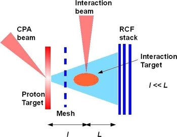
Laser-driven proton beams, accelerated via the so-called transverse normal sheath acceleration (TNSA) mechanism (Snavely et al., Reference Snavely, Key, Hatchett, Cowan, Roth, Phillips, Stoyer, Henry, Sangster, Singh, Wilks, Mackinnon, Offenberger, Pennington, Yasuike, Langdon, Lasinski, Johnson, Perry and Campbell2000) present ideal properties for use in a point projection backlighting scheme with the aim of investigating the transient properties of a plasma or an interaction target. While this type of technique has been used in some experiments to infer the density profile of a dense plasma (e.g., laser-compressed capsules) (Mackinnon et al., Reference Mackinnon, Patel, Borghesi, Clarke, Freeman, Habara, Hatchett, Hey, Hicks, Kar, Key, King, Lancaster, Neely, Nikkro, Norreys, Notley, Phillips, Romagnani, Snavely, Stephens and Town2006), we will discuss in this paper the case in which the dominant effect revealed by the technique is the presence of quasi-static (i.e., non-oscillating) electric fields in the plasma. This is a type of radiography that depending on the experimental arrangement has been referred to as proton projection imaging or proton deflectometry (Borghesi et al., Reference Borghesi, Kar, Romagnani, Toncian, Antici, Audebert, Brambrink, Ceccherini, Cecchetti, Fuchs, Galimberti, Gizzi, Grismayer, Lyseikina, Jung, Macchi, Mora, Osterholtz, Schiavi and Willi2007; Romagnani et al., Reference Romagnani, Borghesi, Cecchetti, Kar, Antici, Audebert, Bandhoupadjay, Ceccherini, Cowan, Fuchs, Galimberti, Gizzi, Grismayer, Heathcote, Jung, Liseykina, Macchi, Mora, Neely, Notley, Osterholtz, Pipahl, Pretzler, Schiavi, Schurtz, Toncian, Wilson and Willi2008). At a given distance from its source, the transverse density profile of a TNSA proton beam is largely uniform within its cone of divergence of half-aperture ~20°. Nonetheless, due to the high degree of laminarity of the beam, the proton source, while being physically extended, is practically equivalent to a nearly point-like virtual source placed in proximity of the target (Borghesi et al., Reference Borghesi, Mackinnon, Campbell, Hicks, Kar, Patel, Price, Romagnani, Schiavi and Willi2004). This characteristic ensures a point projection image of the interaction region with a geometrical magnification at the detector plane given by M ~ L/l (see Fig. 1).

Fig. 1. (Color online) Sketch of a typical proton radiography arrangement.
The presence of sufficiently large E or B fields will then cause transverse deflections of the probe protons, and the transverse density profile of the beam, n p, will be perturbed accordingly by δn p. These modulations in n p hence serve as a measure of the electric and/or magnetic fields in the region of the interaction.
Under the assumption of small angular deflection (i.e., the different proton trajectories do not cross after deflection) and negligible magnetic fields, the protons are deflected by the transverse electric field component in a way that is linear with the electric field distribution itself. This is because the relative difference of proton deposition on the RCF layers is in fact proportional to the charge density in the interaction region and the transverse electric field distribution, averaged over the longitudinal dimension, can then be easily extracted:
Where ɛp is the proton energy and b is the length of the region of non-zero electric field (Romagnani et al., Reference Romagnani, Borghesi, Cecchetti, Kar, Antici, Audebert, Bandhoupadjay, Ceccherini, Cowan, Fuchs, Galimberti, Gizzi, Grismayer, Heathcote, Jung, Liseykina, Macchi, Mora, Neely, Notley, Osterholtz, Pipahl, Pretzler, Schiavi, Schurtz, Toncian, Wilson and Willi2008).
The proton detector usually takes the form of a series of layers of radiochromic films (RCFs) (Dempsey et al., Reference Dempsey, Low, Mutic, Markman, Kirov, Nussbaum and Williamson2000), commonly referred to as an RCF stack. Proton beams generated via the TNSA mechanism have typically a broadband energy spectrum resulting in different times of flight for different energy components; the intrinsic spectral resolution of the pack, given by its multi-layer arrangement, translates then into temporal framing of the diagnostic with a temporal resolution mainly determined by factors such as the ion burst duration at the source (which is on the picoseconds scale).
3. RADIOGRAPHY OF INTENSE LASER-HOHLRAUM INTERACTIONS
The experimental campaign, carried out at the HELEN facility in AWE (Norman et al., Reference Norman, Andrew, Bett, Clifford, England, Hopps, Parker, Porter and Stevenson2002), investigated the interaction between a heating laser beam as used in ICF experiments (1 ns temporally flat-top, 250 J, λ = 0.52 µm) and the inner surface of a 26 µm thick, 1.5 mm diameter gold hohlraum (see Fig. 2). The proton probe beam (with maximum energy 15–20 MeV), driven by the interaction of the HELEN 100 TW CPA pulse with a 20 µm thick gold foil, was employed to monitor the plasma expansion, via the transverse deflection by the ambipolar electric field associated with the plasma front.

Fig. 2. (Color online) Proton projection images showing the expansion of the plasma inside in the hohlraum, obtained at different times. A sketch is provided as guidance to the interpretation of the images.
The interaction beam was focused by an f/3 lens through the laser entrance hole onto the inner surface of the hohlraum (as illustrated in Fig. 2). Due to the moderate proton energies available on HELEN, the observations were mainly limited to open hohlraums, i.e., cylindrical targets with no end walls, so that the spatial quality of the probing proton beam was not affected by the spreading induced by scattering during propagation through the solid enclosing walls. As it will be discussed later in this article, scattering through the walls is a major issue in this type of diagnosis, as, depending on the proton energy, it can significantly degrade the spatial resolution of the data obtained.
Data exemplifying the features observed are shown in Figure 2; as a rule of thumb, the electric fields are directed from the regions of lighter gray color compared to the background (reduced probe proton flux) toward the regions of darker gray color (increased flux). The feature that is most directly apparent from the raw data is the expansion of an ellipsoidal front inside the hohlraum from the interaction. By varying the optical delay between the CPA and the ns pulse, it was possible to monitor the position of the front (corresponding to the front of the expanding plasma) throughout the whole nanosecond of interaction. In a few hundred picoseconds, the plasma front, moving at about 106 m/s, was seen to reach and overtake the center of the hohlraum (i.e., the position of the fuel capsule in an ICF target). Dewald et al. (Reference Dewald, Glenzer, Landen, Suter, Jones, Schein, Froula, Divol, Campbell, Schneider, Holder, Wmcdonald, Niemann, Mackinnon and Hammel2005) report, for hohlraum targets of the same size and similar laser parameters, a time scale of 5–10 ns to reach the highest radiation temperature inside the hohlraum, further proof of the necessity of slowing down the plasma expansion in order not to let it perturb the capsule compression. From Eq. (1) it is possible to extract the electric field distribution across the plasma front; the parameter b has been chosen, assuming cylindrical symmetry along the laser axis, on the order of the longitudinal size of the plasma front. For all the figures examined, rather than the single-signed hump-like electric field distribution expected in correspondence of plasma expansion in vacuum (Hairapetian & Stenzel, Reference Hairapetian and Stenzel2008), the profile highlights a bipolar nature with a maximum electric field amplitude around 108 V/m. This can be understood considering that, rather than expanding in vacuum, the ablated plasma first expands in low density plasma resulting from ionization of the residual gas present in the vacuum chamber (corresponding to ≈ 10−3 mbar) and, subsequently, interacts with counter-propagating colder plasma resulting from X-ray heating of the opposite hohlraum walls. The interaction with tenuous ambient plasma (or with counter-expanding plasma) can trigger, via two stream instability, a double layer structure (with a single sign electric field distribution) as reported in the literature (Charles, Reference Charles2007). At later times the two stream instability is expected to evolve nonlinearly due to the interaction of the double layer with the hot plasma particles leading to the formation of ion acoustic solitons co-traveling with the expanding plasma front (Roberts & Berk, Reference Roberts and Berk1967). The presence of ion-acoustic solitons tied to the expanding plasma front might then be a possible explanation for the bipolar nature of the electric field distribution detected.
In the second part of the experiment, some shots were taken inserting two 1 µm thick Au foils at the sides of the hohlraum in order to emulate more closely a configuration of indirect drive ICF (Fig. 3a). Although the front position was still visible, it was also clear that the insertion of enclosing walls deteriorated the spatial resolution due to lateral spreading induced by scattering of the protons from the foil, limiting the details and the visibility of the front. In order to quantify the deterioration on the spatial quality of the radiographs induced by the walls and extrapolate diagnostic performance at higher proton energies, three-dimensional simulations of the probing proton beam propagation have been performed using a Monte Carlo scattering code, namely stopping and range of ions in matter (SRIM) (Ziegler et al., Reference Ziegler, Biersack and Littmark1985).

Fig. 3. (Color online) (a) Proton radiography of an enclosed hohlraum interaction: the image has been obtained with a probing energy of 10 MeV. (b) Ratio between the lateral spreading on the RCF detector with and without the insertion of the enclosing gold end-walls as a function of the initial proton beam energy. The effects of scattering in the gold walls become comparable with scattering in the detector at energies close to 30 MeV, where the loss of resolution is not significant anymore.
The results are shown in Figure 3b; as a function of the initial proton energy, the ratio between the simulated spread induced by the entire system (enclosing walls + detector) and the simulated spread induced by the sole detector is plotted as a function of the initial proton energy. As it can be clearly seen, at the proton energies used in this experiment (on the order of 10 MeV), this ratio is significantly above 1, resulting in the blurriness of Figure 3a.
Nevertheless, for higher proton energies (E > 25 MeV), this ratio approaches 1 suggesting that enclosing the hohlraums will not perturb the spatial resolution of the radiographs. It has to be highlighted that such proton energies are routinely achievable using PW lasers (Robson et al., Reference Robson, Simpson, Clarke, Ledingham, Lindau, Lundh, Mccanny, Mora, Neely, Wahlstrom, Zepf and Mckenna2007), that will be available, as diagnostic beams, in laser-ignition facilities.
4. PROTON RADIOGRAPHY OF FILAMENTATION IN GASBAG TARGETS
The proton radiography technique has been used to diagnose the interaction between a 1 ns temporally flat-top, 250 J laser beam and gasbags of different initial gas pressures with and without the insertion of a RPP in the laser path. The gasbag targets (filled with neo-pentane, C5H12) were similar to those previously used on NOVA (Moody et al., Reference Moody, Baldis, Montgomery, Estabrook, Dixit and Labaune1993) formed by gluing polyimide membranes to an aluminum washer 400 µm thick. When inflated, the membrane stretched to a thickness of 350 nm forming an oblate gas volume 2.75 mm major diameter by 2.2 mm minor diameter. The use of an f/3 focusing lens in conjunction with an RPP produced a 250 µm focal spot onto the gasbag surface.
In a sequence of shots, the C5H12 pressure in the target was increased from 0.2 to 0.5 and finally to 0.8 atmospheres. These pressures correspond to electron densities of 0.05, 0.13, and 0.21 times the critical density n c for 0.527 µm light (4 × 10²¹ electrons/cm3). These electron densities were chosen in order to achieve conditions below, near, and above the threshold defined by the so-called figure of merit Q (Dewald et al., Reference Dewald, Glenzer, Landen, Suter, Jones, Schein, Froula, Divol, Campbell, Schneider, Holder, Wmcdonald, Niemann, Mackinnon and Hammel2005) for filamentation onset given by:

where I is the laser intensity, λ is the laser wavelength, n e (n c) is the electron (critical) density, T e is the electron temperature, and f is the beam focal number. In the case where only a RPP is used, the filamentation threshold occurs at Q = 1.
The electron densities were in fact chosen in order to accomplish conditions below, at, and above the filamentation threshold: using Eq. (2) we expect in fact the corresponding Q values to be 0.44, 0.9, and 1.5, respectively. This is concluded on the basis that simulations performed in similar conditions (Meezan et al., Reference Meezan, Divol, Marinak, Kerbel, Suter, Stevenson, Slark and Oades2004) indicate an average electron temperature of 0.8 keV.
The proton radiographs related to these shots are shown in Figure 4. Figure 4d corresponds to the same conditions of Figure 4c apart from the removal of the RPP from the laser path. In all four cases, the proton backlighter was timed to probe the plasma approximately 200 ps after the start of the heating beam. Figure 4a shows a structure in correspondence of the plasma formed on the gasbag wall. However, there is no indication of any filamentary structure propagating to the right of the laser spot. In Figure 4b, the Q value is very close to the threshold value of 1 and there is some indication of filamentary structures of the beam collinear with the laser propagation even though the filaments are not clearly distinguishable yet from modulations of the background. In Figure 4c, with a calculated filamentation figure merit of Q ~ 1.5, significant filamentation is clearly visible, which appears to be co-linear with the beam propagation direction. Finally, a shot taken without phase plate under the same conditions of the one in Figure 4c is shown in Figure 4d. In this case, the filamentation appears to be much stronger than in the previous cases following the f/3 light cone of the incident beam. Data analysis suggests that the plasma is collisionless and it is unlikely to support onset of thermal filamentation (Perkins & Valeo, Reference Perkins and Valeo1974); the spatial wavelength of the filaments detected concurs with analytical models for ponderomotive filamentation onset (Epperlein, Reference Epperlein1990). It is also clear from the raw data that removing the RPP dramatically enhances the filamentation, further proof of the necessity of a spatially smoothed laser beam.

Fig. 4. (a, b, c) Proton radiographs of laser-gasbag interaction for different plasma densities corresponding to conditions respectively below, at and above the filamentation threshold (see text for details). (d) Radiograph taken for conditions of (c) but with RPP removed from the laser path. In all images the laser is incident from the left and the ruler corresponds to 120 µm in the interaction plane. A sketch is provided below the images as guidance to their interpretation.
5. PHASE SPACE ELECTRON HOLE OBSERVATION
In shots taken at early times (~100 ps after the beginning of the interaction) for the laser-hohlraum interaction discussed in Section 3, a perturbation region was observed outside the hohlraum, at the rear side of the laser irradiation spot (Fig. 5). This region of pronounced modulation in the probe proton density (see Fig. 5c), evidence of a modulated electric field distribution, is observed ~300–400 µm from the rear surface of the irradiated target surface plane. Since the structure is seen to move away from the target in different layers, while maintaining its profile, we can categorically exclude that this is a random fluctuation in the proton beam density cross section. Exploiting the multi-frame capability of the detector, this density modulation is seen to propagate with a constant velocity of v ~ (1.6 ± 0.6) × 106 m/s while maintaining a substantially time-independent profile in the co-moving reference frame. Since there cannot be dense plasma at the rear of the target at this early time (plasma ablated from the front cannot reach the rear surface due to the enclosed nature of the target, and a shock would take several nanosecond to propagate through the 26 µm thick Au walls), the modulation must be imprinted in the proton beam cross section by an electrostatic field structure propagating through a tenuous plasma, which can for example be created by photoionization of the residual air embedding the target. There are some characteristics of the observed feature, such as the bipolar structure of the electric field, and the stability of the structure in time, which suggest unambiguously the presence of a soliton-like structure. Other characteristics require knowledge of the ambient plasma conditions at the rear of the target. One-dimensional simulation has been thus performed using a hydrodynamic code including radiation transport (namely, Hyades). Simulations show that at the rear surface of the target, steady and cold plasma is created by photoionization of the residual low density air embedding the hohlraum by the X-rays generated during the main interaction. The average electron density and temperature are predicted to be n e ~ 2.5 × 1012 cm−3 and T e ~ 2 eV, respectively, implying a Debye length of λD ~ 7 µm an electron thermal velocity of ve ~ 106 m/s and an ion-acoustic velocity of CS ~ 3 × 10³ m/s. Based on the knowledge of the range of plasma parameters, we can progress in the interpretation of the data. The high velocity of the structure (hundreds of Mach numbers or, on the other hand, in the range of the electron thermal velocity) is indeed a clear indication of an electron-driven phenomenon, rather than an ion acoustic feature. We can then speculate that the soliton-like structure observed is a phase space electron hole (Bujarbarua & Schamel, Reference Bujarbarua and Schamel1981). These structures are electrostatic excitations in collisionless plasmas characterized by a positive potential hump in which a population of electrons is trapped (Eliasson & Shukla, Reference Eliasson and Shukla2006). They appear to be ubiquitous in space collisionless plasmas and their importance in a wide range of space plasma scenarios has been recently demonstrated (Drake et al., Reference Drake, Swisdak, Cattell, Shay, Rogers and Zeiler2003; Hoshino, Reference Hoshino2003; Koyama et al., Reference Koyama, Petre, Gotthelf, Hwang, Matsuura, Ozaki and Holt1995). They are commonly observed in astrophysical contexts, but very few laboratory observations have been reported in the literature so far (Guio et al., Reference Guio, Børve, Daldorff, Lynov, Michelsen, Pècseli, Juul Rasmussen, Saeki and Trulsen2003; Fox et al., Reference Fox, Porkolab, Egedal, Katz and Le2008). In the case of our experiment, this soliton structure appears to be triggered by the electrostatic potential present at the hohlraum walls. Indeed, once the laser has irradiated the inner surface of the target, a population of hot electrons is created, and accelerated up to energies high enough to let them escape the target; the residual positive charge left inside the walls creates an uniform electrostatic potential. The presence of this potential is made apparent by the proton deflection pattern visible close to the walls (dashed ellipses in Fig. 5). The measured dose modulation is consistent with an electrostatic potential on the order of V = 800 V. Electron holes driven by electrostatic perturbations at the edge of collisionless plasma have been indeed seen in recent PIC simulations (Califano & Lontano, Reference Califano and Lontano2005).

Fig. 5. (Color online) (a) proton radiography of laser-hohlraum interaction at 100 ps after its start. The white dashed rectange highlights the structure of interest. The ruler represents 500 microns. The white dashed ellipses highlight the regions of proton deflections close to the walls. (b) Zoom of the highlighted region. (c) Dose modulation at the detector plane in correspondence to the EH.
The width of the structure (on the order of 10 Debye lengths) is also consistent with a phase space electron hole structure (Hoshino, Reference Hoshino2003). Further details on this data and its analysis are available in (Sarri et al., Reference Sarri, Dieckmann, Brown, Cecchetti, Hoarty, James, Jung, Kourakis, Schamel, Willi and Borghesi2010).
ACKNOWLEDGMENTS
Funding for this research has been provided by the AWE Academic Access Scheme, EPSRC grants EP/E035728/1 (LIBRA Consortium) and EP/C003586/1, by DFG TR 18, GK 1203 and FOR 1048 VR. The authors acknowledge the support of the HELEN Facility laser and target preparation personnel.