INTRODUCTION
Application of Brillouin scattering methods have attracted great attention in recent years (Hasi et al., Reference Hasi, Lu, Li and He2007; Kappe et al., Reference Kappe, Strasser and Ostermeyer2007; Lontano et al., Reference Lontano, Passoni, Riconda, Tikhonchuk and Weber2006; Meister et al., Reference Meister, Riesbeck and Eichler2007; Ostermeyer et al., Reference Ostermeyer, Kong, Kovalev, Harrison, Fotiadi, Mégret, Kalal, Slezak, Yoon, Shin, Beak, Lee, Lü, Wang, Lin, Knight, Kotova, Sträßer, Scheikh-Obeid, RieTsbeck, Meister, Eichler, Wang, He, Yoshida, Fujita, Nakatsuka, Hatae, Park, Lim, Omatsu, Nawata, Shiba, Antipov, Kuznetsov and Zakharov2008; Wang et al., Reference Wang, Lu, Lin, Ding and Jiang2007; Yoshida et al., Reference Yoshida, Fujita, Nakatsuka, Ueda and Fujinoki2007). A very prominent application is laser fusion energy (LFE), which requires very high energy and high power laser output of several megajoules in a few tens of nanoseconds with a high repetition rate around 10 Hz (Nakai & Mima, Reference Nakai and Mima2004). However, the current systems in high energy laser facilities, such as NHELIX (Schaumann et al., Reference Schaumann, Schollmeier, Rodriguez-Prieto, Blazevic, Brambrink, Geissel, Korostiy, Pirzadeh, Roth, Rosmej, Faenov, Pikuz, Tsigutkin, Maron, Tahir and Hoffmann2005), PHELIX (Neumayer et al., Reference Neumayer, Bock, Borneis, Brambrink, Brand, Caird, Campbell, Gaul, Goette, Haefner, Hahn, Heuck, Hoffmann, Javorkova, Kluge, Kuehl, Kunzer, Merz, Onkels, Perry, Reemts, Roth, Samek, Schaumann, Schrader, Seelig, Tauschwitz, Thiel, Ursescu, Wiewior, Wittrock and Zielbauer2005; Kuehl et al., Reference Kuehl, Ursescu, Bagnoud, Javorkova, Rosmej, Cassou, Kazamias, Klisnick, Ros, Nickles, Zielbauer, Dunn, Neumayer, Pert and Team2007), PALS (Jungwirth, Reference Jungwirth2005; Batani et al., Reference Batani, Dezulian, Redaelli, Benocci, Stabile, Canova, Desai, Lucchini, Krousky, Masek, Pfeifer, Skala, Dudzak, Rus, Ullschmied, Malka, Faure, Koenig, Limpouch, Nazarov, Pepler, Nagai, Norimatsu and Nishimura2007; Laska et al., Reference Laska, Jungwirth, Krasa, Krousky, Pfeifer, Rohlena, Ullschmied, Badziak, Parys, Wolowski, Gammino, Torrisi and Boody2006; Torrisi et al., Reference Torrisi, Margarone, Laska, Krasa, Velyhan, Pfeifer, Ullschmied and Ryc2008), and Vulcan Petawatt (Danson et al., Reference Danson, Brummitt, Clarke, Collier, Fell, Frackiewicz, Hawkes, Hernandez-Gomez, Holligan, Hutchinson, Kidd, Lester, Musgrave, Neely, Neville, Norreys, Pepler, Reason, Shaikh, Winstone, Wyatt and Wyborn2005), are operated with a low repetition rate or a single shot due to the thermal problems of the laser materials. The beam combination method using stimulated Brillouin scattering phase conjugate mirrors (SBS-PCMs) is a promising one for the high energy output with a high repetition rate (Kong et al., Reference Kong, Lee, Shin, Byun, Park and Kim1997; Reference Kong, Shin and Kim1999; Basov et al., Reference Basov, Efimkov, Zubarev, Kotov, Mironov, Mikhaĭov and Smirnov1979; Rockwell & Giuliano, Reference Rockwell and Giuliano1986; Valley et al., Reference Valley, Lombardi and Aprahamian1986; Loree et al., Reference Loree, Watkins, Johnson, Kurnit and Fisher1987; Bower & Boyd, Reference Bowers and Boyd1998; Riesbeck et al., Reference Riesbeck, Risse and Eichler2001; Riesbeck & Eichler, Reference Riesbeck and Eichler2007; Kappe et al., Reference Kappe, Strasser and Ostermeyer2007; Ostermeyer et al., Reference Ostermeyer, Kong, Kovalev, Harrison, Fotiadi, Mégret, Kalal, Slezak, Yoon, Shin, Beak, Lee, Lü, Wang, Lin, Knight, Kotova, Sträßer, Scheikh-Obeid, RieTsbeck, Meister, Eichler, Wang, He, Yoshida, Fujita, Nakatsuka, Hatae, Park, Lim, Omatsu, Nawata, Shiba, Antipov, Kuznetsov and Zakharov2008). This beam combined system can resolve the thermal problems by combining beams of small energies after separate amplifications. Furthermore, the high quality output beam can also be obtained from the PCMs of this system, which compensate thermal distortions in the laser amplifiers by generating the phase conjugate waves.
The SBS wave of the PCM has a random phase because it is naturally ignited by thermal noise (Boyd et al., Reference Boyd, Rzążewski and Narum1990). For a coherent beam combined output with SBS-PCMs, therefore, the phase relations between the SBS beams should be locked. For this reason, many previous researchers developed their own techniques to lock the phase difference between SBS beams (Basov et al., Reference Basov, Efimkov, Zubarev, Kotov, Mironov, Mikhaĭov and Smirnov1979; Rockwell & Giuliano, Reference Rockwell and Giuliano1986; Valley et al., Reference Valley, Lombardi and Aprahamian1986; Loree et al., Reference Loree, Watkins, Johnson, Kurnit and Fisher1987; Bower & Boyd, Reference Bowers and Boyd1998). However, their systems have a structural limitation when combining many beams, due to very complicated composition with large number of optical components. To overcome this limitation, Kong et al. (Reference Kong, Lee and Lee2004, Reference Kong, Lee and Lee2005a, Reference Kong, Lee and Lee2005b, Reference Kong, Lee, Lee and Guo2005c) proposed the self phase control technique, which can independently lock and control the phases of SBS waves from each phase conjugate mirrors, with the simple composition of few optical components. Therefore, the output energy can be unlimitedly scaled-up by increasing the number of combined beams. In the previous works, the principle of the self phase control has been demonstrated theoretically as well as experimentally (Kong et al., Reference Kong, Lee and Lee2004, Reference Kong, Lee and Lee2005a, Reference Kong, Lee and Lee2005b, Reference Kong, Lee, Lee and Guo2005c, Reference Kong, Lee and Lee2005d, Reference Kong, Lee, Yoon and Beak2006a, Reference Kong, Yoon, Beak, Shin, Lee and Lee2007; Lee et al., Reference Lee, Kong and Nakatsuka2005; Ostermeyer et al., Reference Ostermeyer, Kong, Kovalev, Harrison, Fotiadi, Mégret, Kalal, Slezak, Yoon, Shin, Beak, Lee, Lü, Wang, Lin, Knight, Kotova, Sträßer, Scheikh-Obeid, RieTsbeck, Meister, Eichler, Wang, He, Yoshida, Fujita, Nakatsuka, Hatae, Park, Lim, Omatsu, Nawata, Shiba, Antipov, Kuznetsov and Zakharov2008). In addition to the self phase control, the long-term stabilization technique has also been developed to compensate the slowly varying phase fluctuation due to the thermal convection of the liquid SBS material (Kong et al., Reference Kong, Yoon, Shin, Beak and Lee2006b, Reference Kong, Yoon, Beak, Shin, Lee and Lee2007, Reference Kong, Yoon, Shin and Beak2008).
In this work, as a further development of the beam combined system, the four-beam combined laser system is constructed with the amplitude division, which splits the main-beam to sub-beams using beam splitters. And the phase stabilization experiment of this four-beam combined system is performed using the self phase control and the long-term stabilization technique.
EXPERIMENT
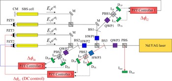
Figure 1 shows the experimental setup for the four-beam combined laser system using self phase controlled stimulated Brillouin scattering phase conjugate mirrors. A 1064 nm Nd:YAG laser (Spectra-Physics, Model #GCR-150) with a line width of ~120 MHz is used for a laser source of the four-beam combined system. This laser has a pulse repetition rate of ~10 Hz, a pulse width of ~8 ns, and a quasi-Gaussian beam profile with ~8 mm diameter. The beam from the laser initially has a p-polarization and passes through the first polarizing beam splitter (PBS). The quarter wave plate (QWP3) with its fast axis at −45° changes the linear polarization to a circular one so that the beam is divided into two parts with almost equal energies at the second PBS. Each divided beam is split into two parts by the PBS again after passing through the half wave plate (HWP1 or HWP2). Consequently, the initial beam is divided into four sub-beams with equal energies. The four sub-beams are reflected by four separated self phase controlled SBS-PCMs, and recombined again at the second PBS. The recombined beam goes to the output part and is reflected at the first PBS rotating its polarization by 90° with the help of the quarter wave plate (QWP3).

Fig. 1. (Color online) Experimental setup for the four-beam combination system with amplitude division: PBS, PBS1, PBS2, and PBS3; polarizing beam splitters, QWP1, QWP2, and QWP3; quarter wave plates, HWP1, HWP2, and HWP3; half wave plates, BS1, BS2, and BS3; beam splitters, D1P, D1S, D2P, D2S, D3P, D3S, and Dout; energy detectors, M; mirrors, CM; concave mirrors, PZT1, PZT2, and PZT3; piezoelectric translators.
The self phase controlled SBS-PCMs used in the experiment is composed by a 300 mm long SBS cell and a concave mirror with a 150 mm focal length. The surface of the concave mirror is high reflection coated with >99% reflectivity. The initial phase of the SBS wave can be locked by just putting this concave mirror behind the cell as shown in Figure 2. In this arrangement, the front part of the incident pump pulse (rE p), reflected at the concave mirror, interferes with the rest of the incident pump pulse (E p). This interference generates the electro-magnetic standing wave inside the cell. The ignition position of the acoustic wave is determined to be one of the nodal points of the standing wave. Therefore, the phase of the acoustic wave can be locked while the phase difference between the nodal points is equal to integer times 2π. In the SBS cell, a heavy fluorocarbon liquid FC-75 (3M company) is used for the SBS generation. It is a well-known SBS material which gives high reflectivity and excellent fidelity (Yoshida et al., Reference Yoshida, Kmetik, Fujita, Nakatsuka, Yamanaka and Yoshida1997).

Fig. 2. Concept of phase control of the SBS wave by the self phase controlled SBS-PCM.
Regardless of the self phase controlled SBS-PCMs, there exist the long-term phase fluctuations of the SBS beams due to the thermally induced convection of the liquid SBS media. This slowly varying long-term phase fluctuation can be easily compensated by active control of piezoelectric translators (PZTs) attached at three concave mirrors except one reference SBS beam, after measurement of the phase relations between the SBS beams. In the two-beam combined arrangement, it is easy to obtain the phase relation between SBS beams using the interfered energy of them. Therefore, first of all, the neighbored SBS beam phases of each two-beam unit are adjusted to the same value by matching one to the other.
Numbering the four SBS beams to Beam1–4 from top to bottom for the convenient expressions, the four-beam system is considered as a combination of a two-beam unit of Beam1 and Beam2 and the other unit of Beam3 and Beam4. The phase of Beam2 can be matched to that of Beam1 by controlling PZT1 for every laser shot, after measurement of the phase relation between Beam1 and Beam2. This phase relation is obtained from the beam reflection at the beam splitter BS1, by measuring the transmitted and the reflected energies of the PBS1 using the pulse energy detectors (D1P and D1S) after passing through the quarter wave plate (QWP1) with its fast axis at 45°. By Jones matrix calculation, the electrical fields of the transmitted (E 1P) and reflected (E 1S) waves of the PBS1 can be obtained as,

where E 1, E 2, φ1, and φ2 are amplitudes and phases of Beam1 and Beam2, respectively, and r 1 is the amplitude of the reflection coefficient of BS1. Then, the relation between the intensities of E 1P and E 1S and the phase difference (Δφ12 = φ1 – φ2) of E 1 and E 2 is


where I 1 and I 2 are the intensities of E 1 and E 2, respectively, and R 1 is the reflectance of BS1. From Eqs (2) and (3), the following equation can be obtained
I ctrl1, calculated from I 1P and I 1S and measured by D1P and D1S, is used for the control signal of PZT1. PZT1 is controlled to make I ctrl1 equal to zero, so that Δφ12 goes to 0 and the phase of Beam2 is matched to that of Beam1. C 12 is experimentally obtained by observing the changes of I ctrl1 during sufficiently long laser shots without control of PZT1. And the stabilized phase difference Δφ12 is obtained from measured I ctrl1 using C 12 with the control of PZT1.
Similarly, after measurement of I 2S and I 2P, the PZT2 control signal I ctrl2 for matching the phase of Beam4 to that of Beam3 can be obtained from the following equation,
where I 3 and I 4 are the intensities of E 3 and E 4, respectively. C 34 is experimentally obtained by observing the changes of I ctrl2 during sufficiently long laser shots without control of PZT2. And the stabilized phase difference Δφ34 is obtained from the measured I ctrl2 using C 34 with the control of PZT2.
The electrical field of the recombined output of the two-beam units after passing through the QWP3 can be expressed as,

Assuming that PZT1 and PZT2 are well-controlled so that Δφ12 = φ1 – φ2 ≈ 0 and Δφ34 = φ3 – φ4 ≈ 0, the four-beam combined output energy with s-polarization is
![\eqalign{I_{out} & ={1 \over 4} \left\vert \lpar E_1 e^{i\phi _1} + E_2 e^{i\phi_2}\rpar + \lpar E_3 e^{i\lpar \phi _3 - \pi /2\rpar } + E_4 e^{i\lpar \phi _4 - \pi /2\rpar }\rpar \right\vert^2 \cr & \approx {1 \over 4} \left\vert \lpar E_1 + E_2 \rpar e^{i\phi_1} + \lpar E_3 + E_4\rpar e ^{i\lpar \phi _3 - \pi /2\rpar }\right\vert^2 \cr &= {1 \over 4} \left[\left(I_1 + I_2 + 2\sqrt{I_1 I_2}\right)+ \left(I_3 + I_4 + 2\sqrt{I_3 I_4}\right)\right. \cr &\quad \left. +\, 2\left(\sqrt{I_1 I_3} + \sqrt {I_1 I_4} + \sqrt{I_2 I_3} + \sqrt{I_2 I_4 }\right)\cos \left(\Delta \phi_{13} + {\pi \over 2}\right)\right]. \cr}](https://static.cambridge.org/binary/version/id/urn:cambridge.org:id:binary:20151022040155221-0038:S026303460900024X_eqn7.gif?pub-status=live)
For maximizing the four-beam combined output energy, the phase difference between the output phase of one two-beam unit (Beam3 and Beam4) and that of the other two-beam unit (Beam1 and Beam2) is controlled to be π/2 by applying the appropriate direct current voltage to both PZT2 and PZT3, after measurement of the phase relation between Beam1 and Beam3. This phase relation is obtained from the beam reflection at the beam splitter BS3, by measuring the transmitted and the reflected energies of the PBS3 using the pulse energy detectors (D3P and D3S) after passing through the half wave plate (HWP3) with its fast axis at 22.5°. By Jones matrix calculation, the electrical fields of the transmitted (E 3P) and reflected (E 3S) waves of the PBS3 can be obtained as

where r 3 is the amplitude of the reflection coefficient of BS3. The relation between intensities of I 3P and I 3S and the phase difference (Δφ13 = φ1 – φ3) of E 1 and E 3 can be expressed as,
![\eqalign{I_{3P} & ={R_3 \over 2}\left\vert \lpar E_1 e^{i\phi _1 } + E_2 e^{i\phi _2 } \rpar + \lpar E_3 e^{i\phi _3 } + E_4 e^{i\phi _4 }\rpar \right\vert^2 \cr & \approx {R_3 \over 2}\left\vert \lpar E_1 + E_2 \rpar e^{i\phi _1 } + \lpar E_3 + E_4 \rpar e^{i\phi _3}\right\vert^2 \cr & = {R_3 \over 2}\left[\Big(I_1 + I_2 + 2\sqrt {I_1 I_2 }\Big)+ \left(I_3 + I_4 + 2\sqrt{I_3 I_4}\right)\right. \cr & \quad \left. +\, 2\left(\sqrt{I_1 I_3 } + \sqrt{I_1 I_4 } + \sqrt {I_2 I_3 } + \sqrt{I_2 I_4 }\right)\sin \left(\Delta \phi _{13} + {\pi \over 2}\right)\right].}](https://static.cambridge.org/binary/version/id/urn:cambridge.org:id:binary:20151022040155221-0038:S026303460900024X_eqn9.gif?pub-status=live)
![\eqalign{I_{3S}&={{R_3 } \over 2}\left\vert { - \lpar E_1 e^{i\phi _1 } + E_2 e^{i\phi _2 } \rpar + \lpar E_3 e^{i\phi _3 } + E_4 e^{i\phi _4 } \rpar } \right\vert ^2 \cr & \approx {{R_3 } \over 2}\left\vert { - \lpar E_1 + E_2 \rpar e^{i\phi _1 } + \lpar E_3 + E_4 \rpar e^{i\phi _3 } } \right\vert ^2 \cr & = {R_3 \over 2}\left[\Big(I_1 + I_2 + 2\sqrt {I_1 I_2 }\Big)+ \left(I_3 + I_4 + 2\sqrt{I_3 I_4}\right)\right. \cr & \quad \left. -\, 2\left(\sqrt{I_1 I_3 } + \sqrt{I_1 I_4 } + \sqrt {I_2 I_3 } + \sqrt{I_2 I_4 }\right)\sin \left(\Delta \phi _{13} + {\pi \over 2}\right)\right]}.](https://static.cambridge.org/binary/version/id/urn:cambridge.org:id:binary:20151022040155221-0038:S026303460900024X_eqn10.gif?pub-status=live)
where R3 is the reflectance of BS3.
And the control signal I ctrl3 can be obtained from the following equation,

Measuring I ctrl3 from I 3P and I 3S, PZT2 and PZT3 are controlled to make I ctrl1 zero so that Δφ13 + π/2 goes to 0 and I out maintains a maximum value. C 13 is experimentally obtained from observing the changes of I ctrl3 during sufficiently long laser shots without control of PZTs. And the stabilized phase difference Δ φ13 is obtained from measured I ctrl2 using C 13 with control of PZTs.
The experimental results of the phase differences (Δφ12, Δφ34 and Δφ13 + π/2) using PZT controls are shown in Figure 3. The phase differences between the SBS waves are well-stabilized during 2000 shots (200 s). The standard deviations of Δφ12, Δφ34, and Δφ13 are measured to be λ/34.3, λ/44.1, and λ/37.6, respectively. Figure 4 shows the four-beam output energy during 2000 shots (200 s). The output energy is well-stabilized and the measured energy fluctuation is 6.16% by standard deviation. Although some abrupt energy drops are observed in the experiment, the output energies of 86.4% of the laser shots (1728 shots) are above 90% to the maximum value of all 2000 shots.

Fig. 3. Measured phase differences between the SBS beams during 2000 shots (200 s): (a) Δφ12, (b) Δφ34, and (c) Δφ13 + π/2.

Fig. 4. (Color online) Four-beam combined output energy during 2000 shots (200 s).
CONCLUSION
In conclusion, the four-beam combined laser system is constructed with self phase controlled SBS-PCMs. For compensation of thermally induced long-term phase fluctuation, the PZTs are actively controlled by the concave mirror positions, so that all the phases of SBS beams are fixed at one reference. The phase differences between the SBS waves are well-stabilized with a standard deviation of less than λ/30 during 2000 shots (200 s) using the PZT controls. Finally, the stabilized four-beam combined output energy is obtained with 6.16% by standard deviation during 2000 shots (200 s). Infrequently, abrupt phase jumps are observed in this system. However, the output energies of 86.4% of the laser shots are above 90% of the maximum value of all 2000 shots.
This work of the four-beam combination is very meaningful, because it verifies that our beam combination can be extended to a many-beam combined system. The experimental setup, however, does not include the laser amplifiers and is just for the phase stabilizations of the four SBS beams. For demonstration of a practical beam combined system, optical amplifiers will be inserted to this four-beam combined system soon.
ACKNOWLEDGEMENT
This work is supported by KAIST with “High-Risk High Return Project,” and International Atomic Energy Agency (IAEA) as a part of the coordinated research project, “Pathway to Energy from Inertial Fusion – An integrated approach (Research Contract No. 13758/R0).”