


1. INTRODUCTION
Supersonic plasma jets production in laboratory conditions becomes an important issue in high-energy density physics, laboratory astrophysics, material processing, and the like. Most attempts to generate laboratory jets were performed at laser facilities, for example, NOVA and GEKKO XII (Farley et al., Reference Farley, Estabrook, Glendinning, Glenzer, Remington, Shigemori, Stone, Wallance, Zimmerman and Harte1999; Shigemori et al., Reference Shigemori, Kodama, Farley, Koase, Estabrook, Remington, Ryutov, Ochi, Azechi, Stone and Turner2000), Omega (Coker et al., Reference Coker, Wilde, Foster, Blue, Rosen, Williams, Hartigan, Frank and Back2007; Hartigan et al., Reference Hartigan, Foster, Wilde, Coker, Rosen, Hansen, Blue, Williams, Carver and Frank2009), and PALS (Kasperczuk et al., Reference Kasperczuk, Pisarczyk, Borodziuk, Ullschmied, Krousky, Masek, Rohlena, Skala and Hora2006, Reference Kasperczuk, Pisarczyk, Demchenko, Gus'kov, Kalal, Ullschmied, Krousky, Masek, Pfeifer, Rohlena, Skala and Pisarczyk2009). However, convergent plasma flows were generated also at the wire array Z-pinch (Lebedev et al., Reference Lebedev, Chittenden, Beg, Bland, Ciardi, Ampleford, Hughes, Haines, Frank, Blackman and Gardiner2002). Magnetically driven jets were produced there using radial or conical wire arrays, which consisted of a pair of concentric electrodes connected by thin metallic wires. A 1 MA current, rising over 240 ns, was applied to the array. Laboratory experiments at the DPF-1000U device (Kasperczuk et al., Reference Kasperczuk, Paduch, Tomaszewski, Miklaszewski, Szymaszek and Zielinska2016) present new attractive possibilities for creation of metallic plasma jets with the use of a plasma focus (PF) device.
The PF devices are usually used as thermonuclear facilities, in which deuterium (D2) plays a role of working gas. Any impurity of D2, in particular impurities with high atomic number (Z), can lead to a certain degradation of the thermonuclear processes. Nevertheless, an erosion of material of the inner electrode traditionally causes a contamination of D2 plasma. The impurities, as a by-product in the PF discharge, are mainly located in the vicinity of the inner electrode face. In the case of a flat face of the inner electrode, a plasma sheath radial motion (during the collapse stage) is finished on the PF axis where a plasma column is created. The nearly cylindrical configuration of the pinched plasma prevents an axial flow of the plasma. In consequence, the impurities are trapped in a region neighboring with the inner electrode face. Therefore, in this case, the impurities only in a little degree influence on processes appearing in a farther part of the plasma column.
Our previous paper (Kasperczuk et al., Reference Kasperczuk, Paduch, Tomaszewski, Miklaszewski, Szymaszek and Zielinska2016) concerned a possibility of adaptation of the PF device for a generator of cumulated streams (jets) of metallic plasma with the atomic number significantly greater than that of D2. Because, by contrast with D2, a Cu plasma resulting from the inner electrode erosion is characterized by relatively high Z (29), thus it was directly used for this aim. Our investigations of the plasma sheath dynamics using the flat face of the inner electrode (Kasperczuk et al., Reference Kasperczuk, Kumar, Miklaszewski, Paduch, Pisarczyk, Scholz and Tomaszewski2002) have shown that the plasma sheath velocity in the radial direction grows linearly with its decreasing position on the inner electrode face, reaching a maximum value on the axis. The induction of the plasma sheath axial motion in the vicinity of the inner electrode, necessary for the plasma jet creation, was forced by us using the conically shaped inner electrode face. Then, the geometry of the plasma sheath collapse became not cylindrical but conical, with significant axial velocity component. Such modification of the inner electrode face allowed to realize successfully both the Cu plasma acceleration and its compression. So, this approach for the metallic plasma jet production proved to be promising. Then, it was our intention to improve the Cu plasma jet parameters (its density and velocity) using an optimum Cu cone geometry. For optimization of the cone geometry, numerical simulations of the plasma jet creation for selected copper cones were performed. Our interest was also obtaining more information relevant to the launching mechanisms of the Cu jets, that is, processes of melting and evaporation of the Cu material during the plasma sheath propagation along the Cu cone surface as well as processes accompanying the magnetic compression of Cu plasma surrounded by the D2 plasma. The computation results deliver new interesting information and allowed us to choose the optimum cone. Experimental results presented in the paper concern the Cu plasma jet produced with the use of a copper cone with diameter in base of 10 cm and height of 5 cm.
2. EXPERIMENTAL SETUP AND CONDITIONS
The experimental investigations were performed with the use of the DPF-1000U device (Scholz et al., Reference Scholz, Miklaszewski, Gribkov and Mazzetti2000), which is equipped with Mather-type two coaxial electrodes 460 mm long. The cathode of diameter 400 mm was composed of 12 stainless-steel pipes distributed symmetrically around the anode and forming a cylinder with a diameter of 400 mm (Fig. 1a). The anode is a copper tube 229 mm in diameter. The electrodes are separated by an insulator with a length of 103 mm.

Fig. 1. The DPF1000U device electrodes setup: (a) the traditional arrangement, (b) design details of the conical insert, and (c) a general view of the conically shaped inner electrode face.
The measurements were performed at a capacitors charging voltage 16 kV, stored energy equal to 170 kJ, and the maximum current amounting to 1.2 MA. The initial pressure of the D2 filling was 0.9 Torr.
Usually, the inner electrode front is closed by a flat plate. However, in our experiment, a profile of the inner electrode face was changed. Namely, a copper cone with diameter in base of 10 cm and height of 5 cm was centrally fixed to the face of the inner electrode. An elongated tip of the cone ensured a larger amount of the Cu plasma and its better repeatability from shot to shot. The DPF-1000U device electrodes setup and the cone profile are presented in Figure 1b, 1c.
Two main diagnostics have been used in the experiment: a 16-frame laser interferometer and a four-frame X-ray camera. The interferometric measurements were performed with a Nd:YLF laser operated at the second harmonics (527.5 nm). The laser pulse (lasting <1 ns) was split by a set of mirrors into 16 separated beams, which passed through a Mach–Zehnder interferometer. Those beams penetrated through the plasma region during a period of 210 ns. The high-speed, four-frame soft X-ray camera (HS-4F-SXRC) was used to record plasma images in extreme UV and soft X-ray spectral ranges with nanosecond temporal and sub-millimeter spatial resolutions. This camera, developed by the ACS Laboratory, is a brand-new equipment based on four sectors, gateable microchannel plate, which cooperates with a set of four pinholes. During the experiment, the pinholes remained uncovered. It allowed recording plasma images within a relatively wide spectral range of 10–6200 eV.
The diagnostics used in the experiment ensured full visualization of the Cu plasma jet creation and its further evolution. A low radiation intensity of the D2 plasma in the soft X-ray range did not allow it to be recorded by means of the X-ray camera. However, the X-ray camera, thanks to its high spatial resolution, proved to be appropriate for detailed observation of the Cu plasma jet. Interferometric measurements, except visualization of both the plasmas, delivered data for their quantitative analysis.
The line-of-sight of both the diagnostics was oriented perpendicularly to the main axis of the PF1000U device with an angle of 45° between them (Fig. 2).

Fig. 2. The location of the high-speed frame imaging systems at the DPF1000U experimental chamber.
3. NUMERICAL SIMULATIONS OF THE CU PLASMA JET CREATION
To get more detailed insight into mechanisms of the copper plasma jet formation, a two-dimensional (2D) MHD numerical code KAROL was used. The code solves equations of the non-ideal, two-temperature (T e, T i) MHD model for the PF plasma sheath driven by magnetic piston. Dynamics in the solid region was described by viscous-plastic equations with the Johnson–Cook model of material strength. The processes of melting and vaporization were taken into account (Marczak et al., Reference Marczak, Jach, Świerczyński and Strzelec2010). Numerical method based on the meshless – ‘free point’ method (Jach et al., Reference Jach, Morka, Mroczkowski, Panowicz, Sarzyński, Stępniewski, Świerczyński and Tyl2001) is capable to handle complicated geometrical configurations like the ones corresponding to various cones attached to cylindrical inner electrode of the PF.
Exemplary results of the plasma sheath dynamics modeling with the use of the code KAROL are presented in Figure 3, in which spatial distributions of the D2 plasma electron temperature for three successive phases of plasma evolution: a plasma sheath motion along the cone surface, a pinch formation and a jet development are shown.

Fig. 3. Spatial distribution of the plasma electron temperature for the three successive phases of plasma evolution: motion along the cone surface, pinch formation, and jet development.
Unfortunately, due to very high-density ratio of the D2 plasma and solid material of the inner electrode (copper), it was impossible to perform complete modeling of the most important phenomena occurring inside a very thin layer (~1 µm) at the D2 plasma–copper material contact, such as an evaporation of copper material from the electrode surface, its diffusion into D2 plasma, etc. However, to come to some conclusions on a possible mechanism of the jet creation, a special numerical methodology was elaborated. This methodology consists of the following three steps:
-
1. A time history of temperature of the D2 plasma layer adjacent to the cone surface was recorded for six points (k = 1 – 6) distributed uniformly along the cone surface (see Fig. 4).
-
2. In the second step, a special 1D version of the code KAROL with refined mesh in the thin layer of the metallic cone surface was prepared. In order to model processes of melting, boiling, and evaporation of copper material, which accompany sliding of the plasma sheath along the cone surface, the three different values of electron plasma temperature, that is, T e = 10, 25, 50 eV, were applied as boundary conditions on the metallic surface of the 1D code. In Figure 5, time courses of the temperatures inside the thin (~1 µm) copper layer, where T m and T v denote temperatures of melting and vaporization of copper are presented. Comparing time waveforms of the surface temperature (thermal load on the cone surface) in Figure 4 with the metallic layer response to the load in Figure 5, one can conclude that the duration of the load (at least for points k = 4–6) lasts long enough to cause vaporization of copper material. It means that an intense emission of the copper vapor from the metallic surface takes place already in the middle of the cone side length and intensifies with increasing velocity of the plasma sheath during its motion toward the cone tip. The evaporated atoms of copper are then swept and carried along by the hot plasma sheath.
-
3. To model propagation of the coper plasma jet, a set of evenly distributed markers was initially placed on the cone surface (see a blue line at the cone surface in Figure 6 at t = 0 ns). Then, the plasma flow sweeps the markers showing trajectory of the copper ions captured by the D2 plasma. During the pinch development phase, the D2–copper plasma swept from the cone surface, as well as the D2 plasma adjacent to the cone surface, forms a thin column. This column is still compressed by the magnetic field and its length grows in the time.

Fig. 4. Plasma temperature versus time at the six points uniformly distributed on the cone side surface (see insert).
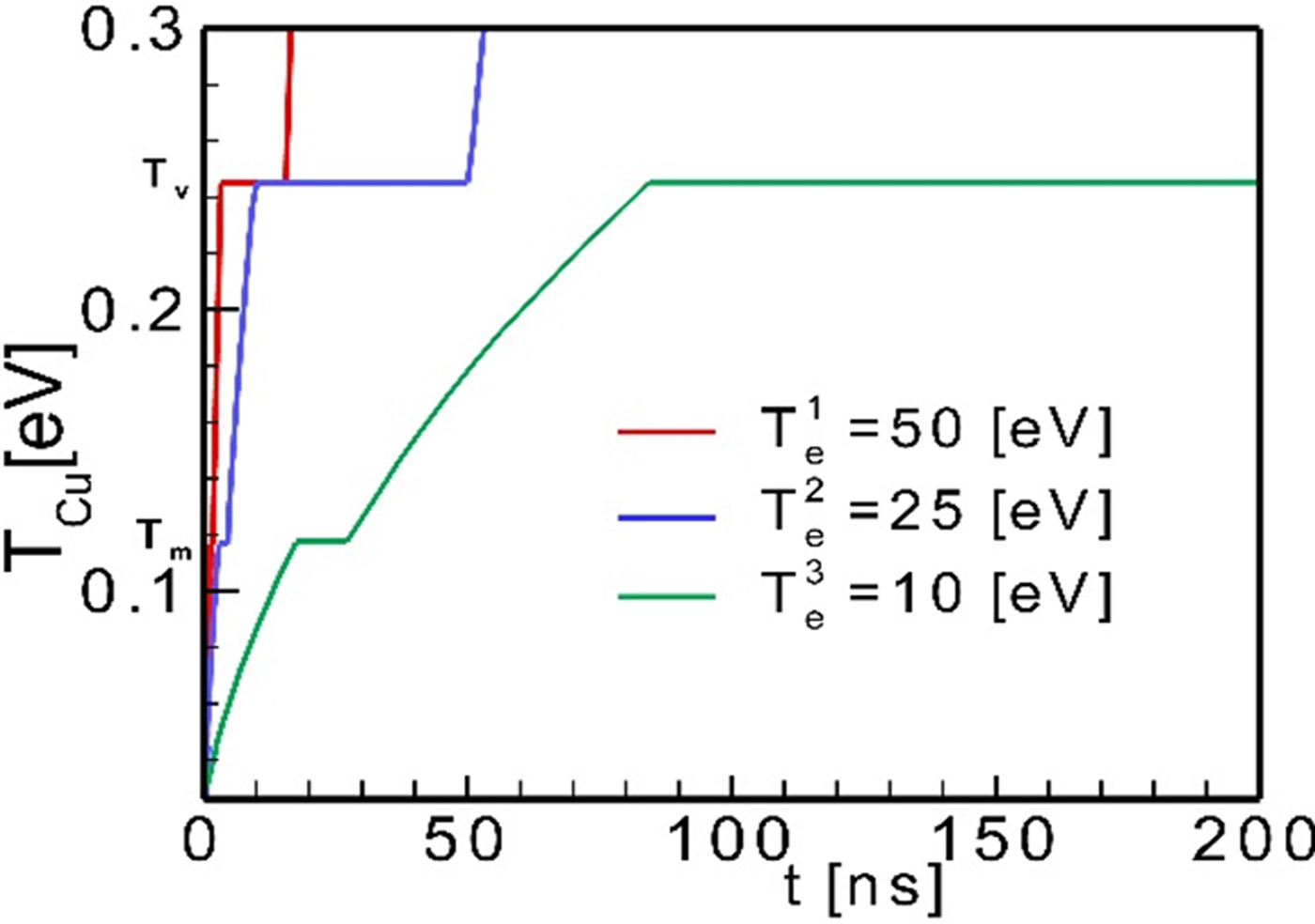
Fig. 5. Results of modeling using 1D code – temperature inside the thin (1 µm) layer of copper subjects to the thermal load (Heviside step function) for T e = 10, 25, 50 eV.
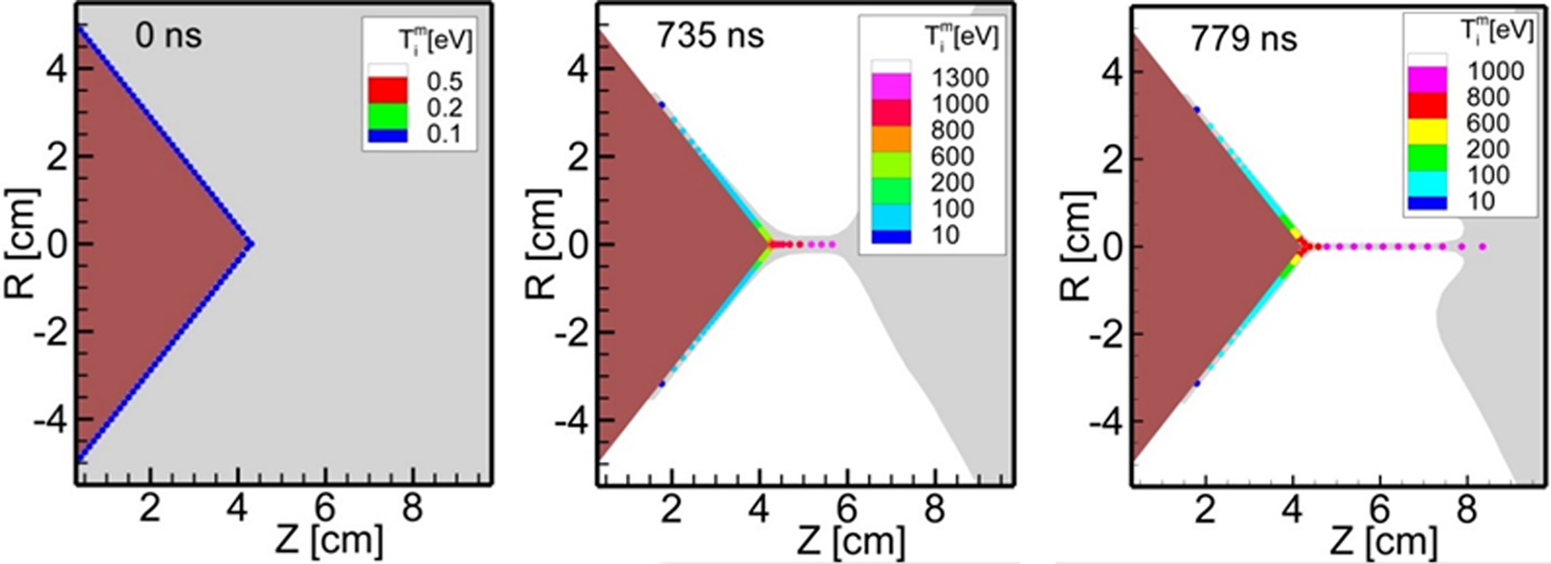
Fig. 6. The set of markers on the cone side surface (t = 0 ns) and their motion in course of the pinch formation phase (t = 735 and 779 ns), corresponding to the motion of the copper–deuterium plasma mixture.
Now, let us concern with the main aim of this paper, namely the optimization of parameters of a copper plasma jet produced at the DPF-1000U device. This optimization is understood as achievement of a thin, long, and stable copper plasma structure, moving with high velocity in axial direction. In order to find the cone configuration which would be able to fulfil the above requirements, four runs of the 2D MHD numerical code KAROL were done for the following cone heights: h = 2, 3, 4, and 7 cm (keeping their diameter in base equal to 10 cm). In Figure 7, we present results of these runs showing the maximum length of the stable copper jets achieved for each configuration.
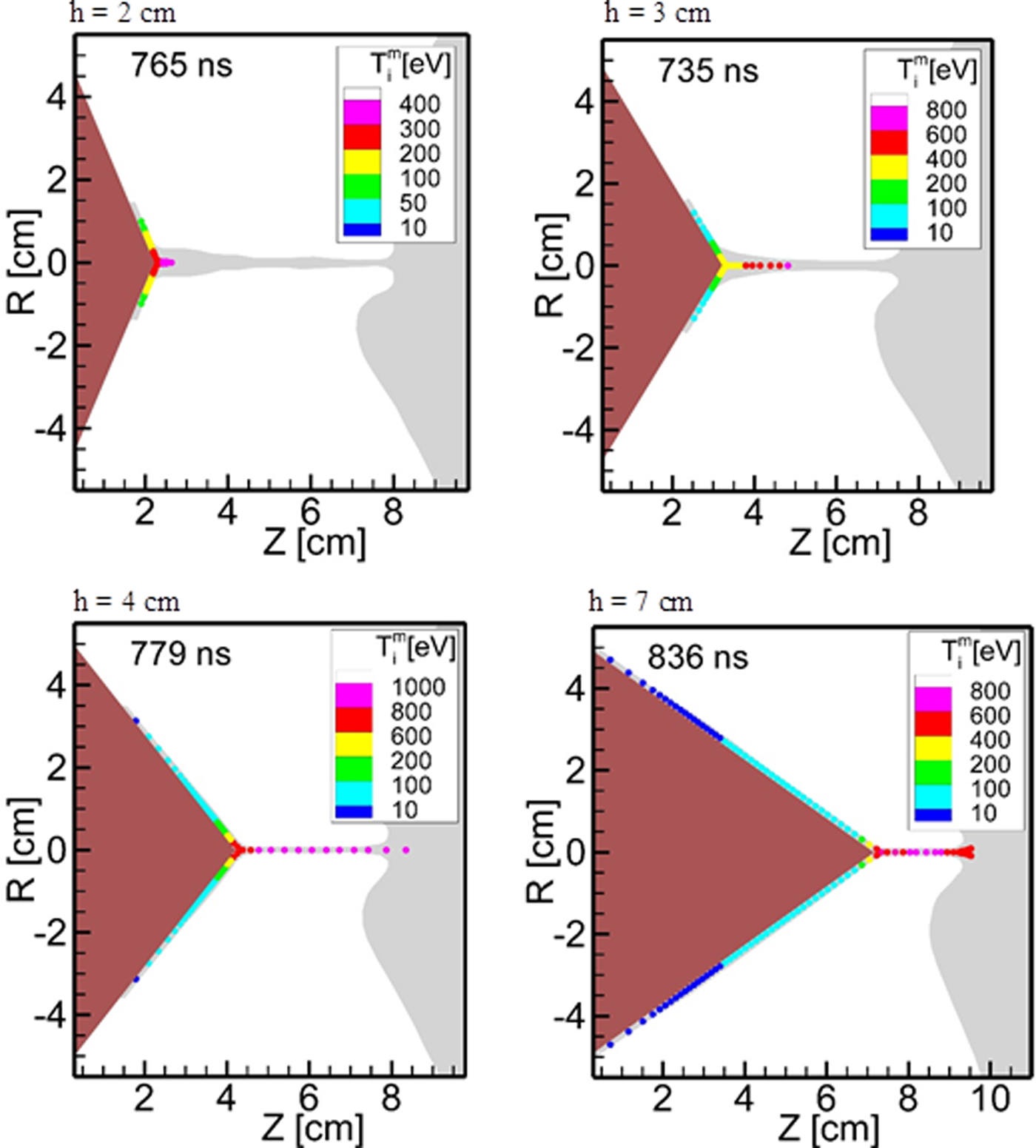
Fig. 7. Maximum length of the stable copper jets for four values of the cone height (2, 3, 4, and 7 cm).
Results of computer modeling have shown that the longest, stable jets should be achieved experimentally for the cone heights in the range of 4 and 7 cm. In our opinion, the cone of 5 cm in height seemed to be most promising. Therefore, this cone was tested in the experiment.
4. EXPERIMENTAL RESULTS
The measurements with the use of the diagnostics described in Section 2 allowed one to obtain some information relevant to the launching mechanism of the Cu jets. Generally, the process of Cu plasma jet production can be divided into two different phases: (i) an induction of the plasma sheath axial motion and, then (ii) the Cu plasma production and collimation. The instant of t = 0 in figures corresponds approximately to the Cu plasma jet start.
The sequence of interferograms in Figure 8 covers both these phases. The first phase, when a conical form of the plasma sheath collapse is formed, is shown in the first three interferograms. One can see that using the conically shaped inner electrode face, the geometry of the plasma sheath collapse becomes also conical, with significant axial velocity component. The first phase lasts until the plasma sheath motion along the cone surface is over. The resulting conical-like geometry of the collapsing plasma sheath induces an axially moving plasma stream as well as the strong pressure gradient along the axis caused by successive pinch formation. It creates conditions for the Cu plasma jet production.

Fig. 8. Sequence of interferograms corresponding to the Cu plasma jet development.
When the plasma sheath, in the course of its travel along the cone surface, is coming near to the axis, the erosion of the Cu material grows. Bearing in mind the numerical results devoted to the copper vapor emission from the metallic surface (see Fig. 4), it should be pointed out that they are in very good accordance with the experimental ones. An intensity of the Cu erosion increases until the plasma sheath reaches the cone tip. This is evidenced by the brightly luminous cone tip seen in the first sequence of X-ray images in Figure 9. The mechanism of the evaporation of the Cu and its fast ionization is presented in Section 3. Generally, one can say that high temperature in the plasma sheath accelerated along the cone surface is responsible for this process. The surface of cone is exposed to a heavy thermal load that, due to convergent nature of the collapse geometry, is focused at the cone tip area.

Fig. 9. Sequences of X-ray images of the Cu plasma jet creation and disintegration.
The X-ray images of the Cu plasma jet in Figure 9 provide evidence of a distinct border between the D2 and Cu plasmas. It argues that the D2 plasma is not transparent for the Cu plasma.
For a better understanding of the launching mechanism of the Cu plasma jet, numerical reconstructions of the spatial electron density of the plasmas n e(r, z) on the basis of interferograms placed in Figure 8 were carried out. The selected results concerning the Cu plasma jet propagation in the D2 plasma envelope are presented in Figure 10. Additionally, to demonstrate the D2–copper plasmas interaction in the cone tip vicinity, the electron density distributions at the plasma cross-sections 0.25 cm distant from the cone tip are plotted (Fig. 11). The conically convergent plasma sheath, shortly before reaching the axis, generates the fast axial plasma stream, in which the D2 plasma plays a role of an ambient medium for the Cu one. The jet-like Cu plasma stream is initially injected with a velocity of 2 × 107 cm/s into the moving D2 plasma, an electron density of which is initially on the level of 1 × 1018 cm−3. When the plasma sheath nears the cone tip, the tip becomes a productive source of the Cu plasma, as demonstrated by the electron density distributions in Figure 11 at t = 35 ns. On the other hand, the growing pressure of the azimuthal magnetic field induces a gradual increase of the ambient D2 plasma density (see Fig. 10). Therefore, despite the increasing Cu plasma amount, the D2 plasma envelope is still able to compress it to the jet-like form. The Cu plasma jet at an instant of 65 ns reaches the electron density n e = 7 × 1018 cm−3 at 3 mm (full width at high maximum) in diameter (see Fig. 11). Such a strong compression of the Cu plasma bears witness to a considerably higher thermal pressure of the D2 plasma compared with that of the Cu plasma. As a result, the Cu plasma jet velocity progressively increases reaching the maximum value of 5 × 107 cm/s.

Fig. 10. Sequence of electron density distributions of plasma streams computed on the basis of selected interferograms in Figure 3.
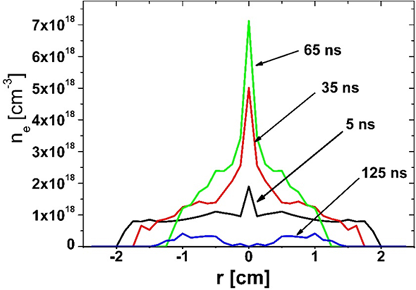
Fig. 11. Electron density distributions at the plasma cross-sections 0.25 cm distant from the cone tip at different instants of the Cu plasma jet evolution.
The plasma sheath collapse is culminated in the pinched plasma column creation. When the conical insert is used, the plasma column length becomes shorter compared with that in the case of the inner electrode flat face. Therefore, a whole available energy is deposited in a considerable diminished plasma amount. Therefore, an evolution of the plasma column and, in consequence, its disintegration run here faster. The decay of the plasma column in the cone tip area terminates further production of the Cu plasma.
The processes of the Cu plasma jet breakdown by a MHD m = 0 instability development and then its disintegration are clearly seen in Figure 9. The instability develops only in the pinched plasma column adjacent to the cone tip, whereas a farther part of the Cu plasma conserves its jet-like structure. This part continues its travel reaching at t = 233 ns the distance of 7 cm (see Fig. 9).
5. CONCLUSIONS
In this work, we have demonstrated a simple way of production of metallic plasma jets by using the conically shaped face of the inner electrode of the PF device. Such modification of the inner electrode face allowed one to realize successfully both the Cu plasma acceleration and its compression.
Our previous experiment devoted to the metallic plasma jet generation with the use of the same plasma generator (Kasperczuk et al., Reference Kasperczuk, Paduch, Tomaszewski, Miklaszewski, Szymaszek and Zielinska2016) allowed us to affirm that the plasma focus device can be successfully employed as a generator of collimated metallic plasma streams. However, to produce a good quality of such streams, a choice of optimum geometry of the central electrode face is necessary. Unfortunately, in our above-mentioned experiment, the cone with dimensions: 3 cm in height and 10 cm in diameter proved to be not optimal.
For our aim, the optimization of the cone sizes was performed by means of the numerical simulations of the Cu plasma jet creation using the 2D MHD numerical code. The numerical computation results allowed us to select the proper cone geometry. Namely, the cone height was increased to 5 cm. Thanks to that it was possible to obtain the very good-quality Cu plasma jet with the parameters as follows: the diameter of 3 mm, the length up to 7 cm, the electron density n e = 7 × 1018 cm−3, and the maximum velocity of 5 × 107 cm/s. An elongated tip of the cone used delivered a relatively large amount of the eroded Cu plasma with its sufficient repeatability.
Our investigation concerned only one cone material – copper. It seems to be of interest to put the test of other cone materials. Bearing in mind that the eroded material is mainly produced from the cone tip, so only the cone tips made of different materials can be exchanged with conserving the rest.
In the experiment, traditionally D2 as a working gas was employed. However, it is possible to use gases with different atomic numbers. It will allow one to compare processes acceleration and compression of metallic plasmas by the filling gas in dependence on their atomic numbers.
In our opinion, the metallic plasma jets produced at the PF devices can be full of interest for different applications. It is worth mentioning that these jets present similarities with astrophysical objects such as protostellar jets. Dimensionless parameters in both the cases, such as the internal Mach number, the cooling parameter, and the jet-to-ambient density ratio (Ryutov et al., Reference Ryutov, Drake and Remington2000; Nicolai et al., Reference Nicolai, Stenz, Ribeyre, Tikhonchuk, Kasperczuk, Pisarczyk, Juha, Krousky, Masek, Pfeifer, Rohlena, Skala, Ullschmied, Kalal, Klir, Kravarik, Kubes and Pisarczyk2009; Kasperczuk et al., Reference Kasperczuk, Pisarczyk, Chodukowski, Kalinowska, Stepniewski, Jach, Swierczynski, Renner, Smid, Ullschmied, Cighardt, Klir, Kubes, Rezac, Krousky, Pfeifer and Skala2015) correspond one to another. Therefore, a test of interaction of these high-speed well-collimated laboratory jets with gas clouds created by a high-pressure (1–40 bars) supersonic gas nozzle seems to be of interest.
ACKNOWLEDGMENTS
This work was supported by the IAEA CRP RC-19253 grant as well as by Polish Ministry of Science and Higher Education within the framework of the financial resources in the year 2017 allocated for the realization of the international co-financed projects.


