


1. INTRODUCTION
Laser-driven ion acceleration in laser–solid interaction is a complicated process and depends on many parameters. This process has different stages such as ionization, formation of initial preplasma, absorption of laser pulse energy, acceleration of the electrons and evolution of the plasma, induced field creation in plasma, and finally ion propagation during and after the acceleration. Basically, the ion acceleration process during the laser and foil interaction can be explained by different regimes, the most important of which are target normal sheath acceleration (TNSA), shock wave acceleration, radiation pressure acceleration (RPA), and break-out after burner regimes (Daido et al., Reference Daido, Nishiuchi and Pirozhov2012; Haberberger et al., Reference Haberberger, Tochitsky, Fiuza, Gong, Fonseca, Silva, Mori and Joshi2012; Fuchs et al., Reference Fuchs, Antici, d'Humières, Lefebvre, Borghesi, Brambrink, Cecchetti, Kaluza, Malka, Manclossi, Meyroneinc, Mora, Schreiber, Toncian, Pépin and Audebert2006; Macchi et al., Reference Macchi, Borghesi and Passoni2013).
Many applications of mono-energetic ion beams with low emittance, such as medical applications, fast ignition in fusion researches, nuclear physics studies, and novel radiation sources are proposed for cheap laser-driven ion acceleration scheme (Borghesi et al., Reference Borghesi, Fuchs, Bulanov, Mackinnon, Patel and Roth2006; Reference Borghesi, Bigongiari, Kar, Macchi, Romagnani, Audebert, Fuchs, Toncian, Willi, Bulanov, Mackinnon and Gauthier2008; Flippo et al., Reference Flippo, Hegelich, Albright, Yin, Gautier, Letzring, Schollmeier, Schreiber, Schulze and Fernández2007).
However, based on our limited recognition ability, there are some complexities in the determination of dynamical parameters of acceleration and determination of the dominant acceleration regime is difficult. Different acceleration regimes can act simultaneously or in different stages, but there is no specified boundary between them. In a real experiment or simulation, any model can explain all the relevant features, but we can find one model to describe some of the significant properties.
The maximum ion energy, the energy spectrum, the angular distribution, and gain coefficient are some of the properties that can be investigated based on laser intensity, pulse duration, thickness, and target composition in different regimes. In addition to the mentioned effective factors, laser contrast, alignment, and the quality of focused laser beam can cause transformation or even stop the process of ion acceleration. Nevertheless, based on available models they can explain the features of ion beams that are observed experimentally by recognition of the effect of the laser parameters and target.
For increasing the peak particle energy, gain coefficient, and improvement of energy spectrum, numerical mechanisms by the particle-in-cell (PIC) codes have been extensively studied. Most studies are in the RPA regime which, unlike the TNSA, transmits the laser energy with high gain to the most of the target ions. In RPA the femtosecond laser pulse with linear polarization and the intensity greater than 1021 W/cm2 accelerate the nanometer foils with the mechanism named “Laser piston” or “Light sail”. RPA in lower intensities takes place with circular polarization. The occurrence of this process is the need to high contrast of the laser as well as focusing and high intensity of it (>1022 W/cm2 for the light sail mechanism) (Fourkal et al., Reference Fourkal, Veltchev and Ma2009; Schlegel et al., Reference Schlegel, Naumova, Tikhonchuk, Labaune, Sokolov and Mourou2009; d'Humières et al., Reference D'Humières, Brantov, Bychenkov and Tikhonchuk2013).
The propagation of plasma ions with the energy a little more than 1 Mev by radiation of Ps laser pulse on the solid target was shown by Fews in a fast ignition fusion research (Fews et al., Reference Fews, Norreys, Beg, Bell, Dangor, Danson, Lee and Rose1994). After experimental efforts, laser-driven proton beam with peak energy of 55 Mev was observed in 2000 (Snavely et al., Reference Snavely, Key, Hatchett, Cowan, Roth, Phillips and Campbell2000). Actually, in most of the proposed acceleration mechanisms, electrons are the energy transformation intermediate with ions by pondermotive force and other different absorption mechanisms. Electrostatic field induced by charge separation can reach to tens of TV/m which its magnitude is six times greater than traditional RF accelerator. These fields allow particles to accelerate up to a few hundred MeV during a few μm lengths. The measured current beams in these accelerators are in the range of kA or more with transverse spread less than 10−3 mm/mrad (Sagisaka et al., Reference Sagisaka, Nagatomo, Daido, Pirozhkov, Ogura, Orimo, Mori, Nishiuchi, Yogo and Kado2009). Acceleration of protons and heavy ions from two layer foils were investigated by some authors (Eliasson et al., Reference Eliasson, Liu, Shao, Sagdeev and Shikla2009; Wang et al., Reference Wang, Yan, Chen, He, Ma, Bin, Schreiber, Tajima and Habs2013; Eliezer et al., Reference Eliezer, Nissim, Mariamartinezval, Mima and Hora2014).
Recently another research group accomplished experimental results on the proton and carbon ions acceleration form ultrathin polymer films or diamond-like carbon (DLC) thin foils down to 5.3 nm thicknesses and laser intensity of order of 6 × 10¹⁹ W/cm2 (Henig et al., Reference Henig, Steinke, Schnürer, Sokollik, Hörlein, Kiefer, Jung, Schreiber, Hegelich, Yan, Meyer-ter-Vehn, Tajima, Nickles, Sandner and Habs2009). They finally obtained the quasi-mono-energy spectrum characteristic for different kinds of ions. Their simulation results admitted their experimental part and proposed RPA as the dominant acceleration mechanism in the mentioned laser intensity range.
In this paper, optimum condition for the generation of mono-energetic proton beams from different target combinations are examined by numerical 1D3V PIC simulation. Different target compositions are examined such as, pure DLC, DLC foil with hydrogen impurity, DLC foil supported by hydrogen layer, and polystyrene (PS) layer. We describe the acceleration mechanism in the two consequent steps. In the first step, electrostatic shock wave accelerates background ions from the bulk of the foil and in the second step acceleration of electrons and ions are continued by the radiation pressure mechanism. In Section 2, new analytical formalism is explained for acceleration of ions, by reflection from electrostatic shock wave. In this section, acceleration criteria of ions with different charge-to-mass ratio (q/m) are investigated in terms of electrostatic shock amplitude, depth, and velocity. In Section 3, numerical results for ion acceleration for different target structures are reported. Concluding remarks are presented in Section 4.
2. ACCELERATION CRITERIA FROM SHOCK WAVE
In the interaction of intense laser pulse with the overdense plasma, electrostatic shock wave is propagated through the foil. This high amplitude electrostatic shock accelerates background ions which are reflected from the electrostatic field of the shock wave. This electrostatic shock wave approximately, has a triangle like (saw tooth) shape with amplitude E 0 and thickness D which is moving with relativistic velocity. However, for simplicity, we consider rectangular (step-like) electrostatic perturbation with the half of the triangle height E 0/2 (Fig. 1). This electrostatic shock moves forward with the velocity βs = vs/c and affects the charged particles in the plasma interior. The velocity of the relativistic shock wave is as follows (Zhang et al., Reference Zhang, Shen, Li, Jin, Wang and Wen2007):
 $${v_{\rm s}} = \displaystyle{{ - \displaystyle{{{a^2}} \over {{n_i}{m_i}}} + \sqrt {{{\left( {\displaystyle{{{a^2}} \over {{n_i}{m_i}}}} \right)}^2} + \displaystyle{{4{a^2}} \over {{n_i}{m_i}}}}} \over 2},$$
in which a = eA/m ecω is dimensionless laser pulse vector potential amplitude, m i (= m i/m e) is normalized ion mass and n i (= n i/n c) is normalized ion number density to the laser critical density. We follow dynamics of an ion with the charge q 0 and mass m i which locates in front of the shock wave in the laboratory frame. We will show two different scenarios that may have occurred for the ions according to its charge-to-mass ratio and electrostatic shock amplitude, thickness, and velocity. In the first situation, the particle is reflected from the electrostatic shock wave and speeds up forward, whereas in the second one, the particle passes through the electrostatic potential and left behind with a small acceleration (Fig. 1).

Fig. 1. Ion dynamics in saw tooth (triangle-like) electrostatic shock wave with the height E 0 and thickness D moves with velocity βS = vs/c, and its approximated step function with amplitude E 0/2.
The relativistic equation of motion of the ion in the electrostatic shock field is:
 $$F = \displaystyle{{dP} \over {dt}} = \displaystyle{{d({m_i}{\rm \gamma v})} \over {dt}} = {q_0}{E_0}/2,$$
in which 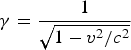 ${\rm \gamma} = \displaystyle{1 \over {\sqrt {1 - {v^2}/{c^2}}}} $ is the relativistic factor of the ion. For simplicity we assume step-like electrostatic shock with high E 0/2 (Fig. 1a). By the integration of this equation, following relations are obtained for the ion velocity and position,
 $$V = \displaystyle{{{c^2}t} \over {\sqrt {{c^2}{t^2} + {A^2}}}} \; \;, \; \quad X = \sqrt {{c^2}{t^2} + {A^2}} - A,$$
where A = 2m ic 2/zeE 0, and z is the ionization degree of ion. It is assumed that the front side of the electrostatic potential is at origin in t = 0, and ion initial conditions are V(0) = 0 and X(0) = 0.
Based on the above equations, the particle reflection condition of the electrostatic shock is calculated with the assumption that the particle orbit does not collide with the rear surface of the electrostatic potential at x = v st−D:
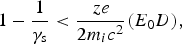 $$1 - \displaystyle{1 \over {{{\rm \gamma} _{\rm s}}}} \lt \displaystyle{{ze} \over {2{m_i}{c^2}}}({E_0}D),$$
where 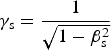 ${{\rm \gamma} _{\rm s}} = \displaystyle{1 \over {\sqrt {1 - {\rm \beta} _{\rm s}^2}}} $. It is obvious from this condition, the electrostatic potential difference of shock field (area under the electrostatic shock field curve, E 0D/2) and shock propagation velocity, play main roles in the reflection of the ion with the charge-to-mass ratio ze/m i. By accounting the dimensionless quantities for electrostatic field and ion mass as:
 $$\tilde m = \displaystyle{{{m_i}} \over {{m_e}}} \cdots, \cdots \tilde E = \displaystyle{{eE} \over {{m_e}c{\rm \omega}}} \cdots, \cdots \tilde D = \displaystyle{{D{\rm \omega}} \over c}.$$
Eventually we will have the following criterion for ion reflection:
Lower limit of  $\tilde D\tilde E$:
 $$\tilde D\tilde E \gt \big(1 - \displaystyle{1 \over {{{\rm \gamma} _{\rm s}}}}\big)\displaystyle{{2\tilde m} \over z}.$$
 According to this condition, the boundaries for  $\tilde D\tilde E$ in terms of the relativistic factor of electrostatic shock wave are drawn in Figure 2, for protons (red curve) and carbon ions (blue curve).Transverse axis is the electrostatic potential difference through the shock, which belongs to its strength, and longitudinal axis γs shows its velocity.

Fig. 2. Reflection criteria of protons (red curve) and carbon ions (blue curve) in terms of the normalized electrostatic shock potential difference and its relativistic factor. Green curve is the electrostatic shock characteristic dynamics from the simulation results of Section 3.
In Figure 2, the red boundary defines the acceleration region for protons and blue line indicates the acceleration region for C+6 ions. Under the red line, charged particle acceleration does not occur while above the blue line both protons and carbon ions can accelerate. Colored area between the two curves indicates an exclusive acceleration region for protons. Green curve in this figure shows electrostatic shock characteristics from simulation results of part 3 in Section 3. Thus, according to this curve in the initial stage of the laser–foil interaction, only protons are accelerated while the carbon ions are left behind.
Accelerated charged particles by the electrostatic shock are released from the shock field at the time  ${t_{\rm 1}} = \displaystyle{{{\rm 4}{{\rm \beta} _{\rm S}} {\rm \gamma} _{\rm S}^{\rm 2}} \over {z\tilde m\tilde E}}$. According to Eq. (1), their relativistic factor at reflection from the shock field will be:
 $${\rm \gamma}= \sqrt {1 + 4{\rm \beta} _{\rm s}^2 {\rm \gamma} _{\rm s}^4}.$$
This relativistic factor is equivalent to the particle reflection with the backward velocity βs in the moving frame of the shock. In the non-relativistic limit, Eq. (7) gives the value β = 2βs for the reflection velocity in the laboratory frame (Macchi et al., Reference Macchi, Cattani, Liseykina and Cornolti2005).
3. NUMERICAL SIMULATION RESULTS AND DISCUSSION
By the early expansions or appearance of instabilities like Rayleigh-Taylor, possibly energy does not transfer to the ions completely. So, the study of the shape, structure, and type of used material for preventing the occurrence of such difficulties can increase the quality of the ion beam. For this purpose, we initially find out the optimum thickness of the pure DLC layer for the production of C6+ ions via 1D3V dimension PIC simulation. Then, by adding a thin hydrogen layer with an appropriate thickness at the back of the carbon layer, we attempt to prevent Rayleigh–Taylor instability (Pegoraro & Bulanov, Reference Pegoraro and Bulanov2007) and to produce mono-energetic protons with high quality. To continue, soft DLC layer (ta-c:H) with 5% hydrogen and 2.7 g/cm3 density is used for optimization of proton acceleration (Schlegel et al., Reference Schlegel, Naumova, Tikhonchuk, Labaune, Sokolov and Mourou2009). Finally, we examine nanometer PS (C8H8) polymer layer as a target. Laser pulse used in our simulation is a right circularly polarized with the intensity of order of 1023 W/cm2 or (a 0 = 200, dimensionless amplitude) and its wavelength is 1 μm. Pulse full-width at half-maximum (FWHM) is 4.5 μm, which results in pulse duration of τFWHM = 15 fs. In the following sections, we present the simulation results for these target structures.
3.1. Determination of Optimum Thickness of Pure DLC Layer
At the first step, we investigate the interaction of the above-mentioned laser pulse with a nanometer layer of pure DLC (ta-c) with the density of 3.5 g/cm3 (Saitoh, Reference Saitoh2012). So, we will have the amount of n 0i = 1.7 × 1023 cm−3 for initial ion density. We suppose all the carbon ions are completely ionized in the interaction with prepulse; then the whole target will be ionized completely and electron density is n 0e = zn 0i and the plasma frequency is ωp = 5.7 × 10¹⁶ s−1. This plasma layer is overdense for our selected laser frequency (ωl = 1.88 × 10¹⁵ s−1) with normalized density ≈1000. Moreover, with consideration of plasma frequency the skin depth of laser on target is l skin = c/ωp ≈ 5.3 nm. These calculations accomplished on simulation box with 72,000 cells and the dimensionless length is  $\tilde L = 7200$ (eight times larger than pulse length). Pulse center is located in
  $\tilde L = 1800$ and the plasma begins from
  $\tilde L = 3600$. There are four carbon ions and 24 electrons in each cell.
For achieving high-energy mono-energetic bunch of C6+ ion, we considered different plasma layer thicknesses L C = 20, 25, 30, 25, 40 nm. Considering the pulse intensity and foil thicknesses, the acceleration happens in the RPA regime. Simulation results, especially energy spectrum, after passing time  $\tilde t = 36,000$, were investigated to determinate the optimum thickness. This is the estimated reflection time of peak pulse from the initial edge of the plasma.
As it is obvious from Figure 3, ions gain maximum energy when the target layer thickness is 25 nm. According to energy distribution function, 37.5% of ions accelerated up to 9.8 GeV (817 MeV/nucleon) in 25 nm thickness. This is compatible with the optimum thickness proposed by the analytical equation L opt = n ca 0λL/2πn e = 31.2 nm in (Snavely et al., Reference Snavely, Key, Hatchett, Cowan, Roth, Phillips and Campbell2000).

Fig. 3. Maximum energy of carbon ions versus target thickness.
Figure 4 shows the energy spread of ions and the percentage of accelerated particles of carbon ions in different thicknesses. The 30 nm thickness of carbon layer has the minimum amount of energy spread and 54.6% of all the particles are accelerated.

Fig. 4. Energy bandwidth and ion acceleration ratio versus target thickness.
3.2. DLC Foil with Additional Hydrogen Layer
In this section, by considering a DLC layer with the same density ρc = 3.5 g/cm3, ρH = o.6 g/cm3 subject to the incidence of a pulse and a hydrogen layer behind it, we try the maximum amount of energy transfers to protons. This hydrogen layer could be due to the hydrocarbon impurity on the target surface. In the accomplished investigations on the DLC layer surfaces after production, the hydrogen bond with shallow carbon was seen. The thickness of this hydrogen layer and their penetration are measurable. In the first step, to find out the optimum hydrogen level of density and thickness in comparison with the DLC layer, we consider three different thicknesses for hydrogen layer L H/L C = 0.5, 1, 1.5. We consider the effect of these parameters on the hydrogen energy spectrum in the RPA regime (Figure 5).

Fig. 5. The schematic view of two layer target, DLC with hydrogen impurity and PS layer.
Also for the DLC layer we consider four different thicknesses L C = 10, 20, 30, 40 nm, so that the ratio of hydrogen layer thickness to the carbon layer thickness is ξ = 0.3, 0.5, 0.7 for each L C. In this section, we extend simulation time to  $\tilde t = 36,000$ until the end of the acceleration mechanism and achieving the final energy of ions; so we increased the simulation box length up to
  $\tilde L = 36,000$, about 40 times over the laser pulse duration (Fig. 6).

Fig. 6. Maximum proton energy based on different layer thickness.
According to the above figure, for the 20 nm DLC layer and 10 nm hydrogen layer thicknesses, protons gain the maximum amount of energy. Now we investigate the proton beam quality for all of the states of L C = 20 nm according to the bandwidth of the energy spectrum and the percentage of accelerated particles. The results show that in the ratio of optimum thickness 0.5, energy bandwidth is 1.78%, but only 36.3% of protons accelerated. By incrementing the thickness ratio of the hydrogen layer up to 14 nm, the percentage of accelerated particles will enhance to 94.4% (Fig. 7).

Fig. 7. Energy bandwidth and protons acceleration ratio versus layers thickness ratio.
In Figure 8, phase space figure is drawn for target elements at the end of acceleration route. The compression of the proton bunch (red points) shows mono-energetic accelerated protons.

Fig. 8. Phase space of electrons (black), protons (red), and C6+ ions (blue).
3.3. Mixed Target of DLC foil with Hydrogen Impurity
There are different kinds of DLC foils with the ability of production in nm range thicknesses. One kind is hard DLC (ta-C:H) layer and another is a soft DLC layer (a-C:H) or semi-polymer carbon which has hydrogen in its structure. In this section, we want to simulate the pulse interaction with these kinds of foils and tried to produce mono-energetic, high-quality, and high-energy proton beams. First, a laser pulse incidents on the nm DLC layer with 5% hydrogen and 2.7 g/cm3. The laser pulse characteristic is similar to the previous sections (1023 W/cm2 intensity or non-dimension laser amplitude a 0 = 200.1 μm wavelength, pulse spread or FWHM is 4.5 μm and pulse duration of τFWHM = 15 fs). Hence, according to density relation for complex targets ρ = n Cm C + n Hm H, where mC and mH are molar mass of carbon and hydrogen, respectively, if we consider the ratio n C/n H = 19, we will have n 0i = 1.42 × 1023 cm−3 for the initial ion density. By the complete ionization of carbon atoms (Z = 6) electron density is n 0e = zn C + n H and the electron plasma frequency ωp = 5.1 × 10¹⁶ S−1. This is more than the laser frequency that is the sign of having an overdense complex plasma beam. Thus, we have got n e/n c ≈ 729. Also, laser skin depth on the target layer is l skin = c/ωp ≈ 6 nm. This simulation was done in box with  $\tilde L = 36,000$ lengths (40 times pulse length) with 306,000 cells. The pulse center was
  $\tilde x = 1530$ and the beginning of the plasma was in
  $\tilde x = 3060$ and eight protons and 152 carbon ions were considered in each cell.
To find a mono-energetic proton bunch with high-energy, plasma beam thicknesses were considered as L p = 20, 30, 40, 50 nm. In this section, we continue the simulation process until the acceleration mechanism is completed ( $\tilde t = 36,000$). The optimum thickness 30 nm is achieved from simulation results (Fig. 9).

Fig. 9. (a) Maximum proton energy. (b) Proton spectrum in different thicknesses.
After the interaction, laser pulse passed the 20 nm thickness target and the full reflection from the 30 nm layer was done after 6 $\Delta \tilde t$, from 40 nm layer after 4.5 and from 50 nm layer after 4
 $\Delta \tilde t$. As figure 9 shows from 30 nm layer we will have protons with higher energies about 1.37 Gev. The main peak of the spectrum from the 30 nm layer includes 41.2% of protons with 1% relative spread of energy (Fig. 10).

Fig. 10. Proton divergence angle and energy bandwidth.
The main peak of the spectrum from the 30 nm layer that has the least divergence angle and the thin energy spectrum include 41.2% of protons and gains the maximum energy.
The green curve in Figure 1 is obtained from the simulation results of the interaction of laser and foil with the above-mentioned parameters. This curve depicts the electrostatic shock characteristics (amplitude, thickness, and velocity) at the times 15.68, 39.21, 70.58, and 78.43 fs, respectively. At the first step of the interaction, the electrostatic shock swept the foil. At this time interval, the electrostatic shock mostly fulfills acceleration conditions for the protons, but C+6 ions do not take part in the acceleration. Therefore, mostly protons are accelerated and carbon ions cannot accelerate in this initial stage. In continuation, the foil will be swept by the laser pulse, while the large amounts of carbon ions remain behind the laser pulse and most of the electrons and protons keep their acceleration stage in front of the laser pulse in the RPA regime (Fig. 8).
3.4. PS Layer
Polymer layers are suitable candidates as targets for proton acceleration from nanometer foils. Few nanometer foils of polymer materials were constructed and illuminated by ultrahigh laser pulses for the generation of high-quality mono-energetic proton beams. In the last part of this section, we examine nanometer PS (C8H8) polymer layer as a target. Figure 11 shows the maximum proton energy as a function of PS thickness.

Fig. 11. Maximum proton energy as a function of PS layer.
In the optimum thickness 50 nm, 84% of protons in the interaction zone are accelerated up to 2.33 GeV with 1.46% energy spread.
4. CONCLUSIONS
In this paper, optimum acceleration conditions of the acceleration of protons from an additional layer of hydrogen or hydrogen impurity on the DLC foil are obtained from 1D3V PIC simulation code. Additionally proton acceleration from lower density PS layer (C8H8) with inherent 50% hydrogen atoms is investigated and compared with DLC results.
Our results show that the thin film of DLC can be a suitable place for energy transportation to the lighter ions, including protons. In the best situation, by selecting the 20 nm for DLC and 10 nm thickness for hydrogen layer, protons can be accelerated up to 1.56 GeV. However, using a 30 nm thickness complex foil with hydrogen as impurity of DLC, protons gain a little less energy with an amount of 1.36 GeV in comparison with the two layers, while more protons can accelerate and their energy spread and divergence are appropriate (Table 1).
Table 1. Accelerated proton beam characteristics from simulation results

It is clear that the 50 nm PS layer with the lowest density 1 g/cm3, is also suitable candidate for high-energy, high-quality mono-energetic proton beam with 2.33 GeV energy by a 15 fs ultrahigh intensity (a 0 = 200, dimensionless amplitude) laser pulse.
In the analytical section, by a new analytical formalism, we introduce acceleration of charged particles and compare acceleration criteria for protons and C+6 ions. In this formalism acceleration criterion in the initial step of interaction of intense laser pulse with foil is investigated. This criterion is obtained by introducing reflection conditions for the charged particles by different charge-to-mass ratio (q/m), from the laser-induced electrostatic shock. Our analytical formalism indicates that charged particles with high charge-to-mass ratio have bigger chance to accelerate by the reflection from the electrostatic shock field. The boundaries of the acceleration regions for protons and C+6 ions are shown in Figure 2 in terms of electrostatic shock field characteristics. Simulation results show (green curve in Fig. 1) that in the early time of the interaction, protons fulfill acceleration criterion, but most C+6 ions have not had enough time to accelerate due to their lower amount of q/m respect to protons and then remain behind the electrostatic shock.


