


Introduction
Fast heating of imploded fuel with an ultraintense short-pulse laser is an attractive approach to realize controllable nuclear fusion (Tabak et al., Reference Tabak, Hammer, Glinsky, Kruer, Wilks, Woodworth, Campbell and Perry1994; Solodov et al., Reference Solodov, Anderson, Betti, Betti, Gotcheva, Myatt, Delettrez, Skupsky, Theobald and Stoeckl2009; Gu et al., Reference Gu, Yu, Zhou, Wu, Wang, Liu, Cao and Zhang2013), which is called fast ignition (FI). Recently developed petawatt (PW) laser systems have realized this scheme in experiments (Theoobald et al., Reference Theoobald, Solodov, Stoeckl, Anderson, Betti, Boehly, Craxton, Delettrez, Dorrer, Frenje, Glebov, Habara, Tanaka, Knauer, Lauck, Marshall, Marshall, Meyerhofer, Nilson, Patel, Chen, Sangster, Seka, Sinenian, Ma, Beg, Giraldez and Stephens2011; Azechi et al., Reference Azechi, Mima, Shiraga, Fujioka, Nagatomo, Johzaki, Jitsuno, Key, Kodama, Koga, Kondo, Kawanaka, Miyanaga, Murakami, Nagai, Nakai, Nakamura, Nakamura, Nakazato, Nakao, Nishihara, Nishimura, Norimatsu, Norreys, Ozaki, Pasley, Sakagami, Sakawa, Sarukura, Shigemori, Shimizu, Sunahara, Taguchi, Tanaka, Tsubakimoto, Fujimoto, Homma and Iwamoto2013; Shiraga et al., Reference Shiraga, Nagatomo, Theobald, Solodov and Tabak2014). In this scheme, the fuel is first compressed to high areal density with nanosecond (ns)-laser beams (~1015 W/cm2), and then the core of the imploded plasma is heated by a relativistic electron beam generated by a high-power picosecond (ps)-laser beam (~1019 W/cm2). However, the ps laser produces a large amount of γ rays simultaneously, and these γ rays strongly interfere with instruments used to detect neutrons. Neutron diagnosis plays an important role in identifying the status of the confined plasma (Habara et al., Reference Habara, Norreys, Kodama, Stoeckl and Glebov2006; Shan et al., Reference Shan, Cai, Zhang, Tang, Zhang, Song, Bi, Ge, Chen, Liu, Wang, Yang, Qi, Tian, Yuan, Zhang, Yang, Jiao, Cui, Zhou, Cao, Zhou, Gu, Zhang, Zhu and He2018) because the complex electromagnetic fields in the plasma do not interfere with the flight of neutrons; thus, such techniques provide hot-spot information. Neutron time-of-flight (nTOF) spectrometry employing a fast organic scintillator is a common method to diagnose the neutron yield, fuel areal density and plasma temperature in laser fusion experiments (Stoeckl et al., Reference Stoeckl, Cruz, Glebov, Knauer, Lauck, Marshall, Mileham, Sangster and Theobald2010; Forrest et al., Reference Forrest, Radha, Glebov, Goncharov, Knauer, Pruyne, Romanofsky, Sangster, Shoup, Stoeckl, Casey, Gatu-Johnson and Gardner2012). Unfortunately, such scintillators also respond to γ rays, making neutron detection challenging in FI because of the strong γ-ray background generated through Bremsstrahlung processes of ~MeV fast electrons.
There are several methods to alleviate this problem. First, the gamma background can be reduced with a suitable lead shield. Second, the response of the scintillator detector to the gamma burst can be suppressed with adequate gating techniques of the photomultiplier tube (PMT). Unfortunately, these two methods are not sufficient, as the high-intensity gamma flash still masks the much weaker neutron signals (Lauck et al., Reference Lauck, Brandis, Bromberger, Dangendorf, Goldberg, Mor, Tittelmeier and Vartsky2009) in experiments. The reason is the long decay time of fluorescence called “afterglow” in conventional organic scintillators, which overwhelms the neutron signals.
Hence, fast organic scintillators with much shorter afterglows are important for inertial confinement fusion (ICF) experiments with strong gamma backgrounds. The oxygen-enriched liquid scintillator (Lauck et al., Reference Lauck, Brandis, Bromberger, Dangendorf, Goldberg, Mor, Tittelmeier and Vartsky2009; Stoeckl et al., Reference Stoeckl, Cruz, Glebov, Knauer, Lauck, Marshall, Mileham, Sangster and Theobald2010) with a ternary mixture of p-xylene as the solvent and 2,5-diphenyloxazole (PPO) and bis(o-methylstyryl)-benzene (bis-MSB) as fluors is known to provide a fast response and negligible afterglow. Dissolved molecular oxygen is an effective quencher of the triplet excited states in the fluor, which are primarily responsible for the afterglow. Benzophenone, another satisfactory quenching agent, can be doped into the plastic scintillator EJ-232 to obtain the EJ-232Q configuration (Eljen, 2013), achieving better timing performance. To detect the relatively weak neutron signals, the gamma-induced lights in the scintillators need to decay for at least four orders of magnitude in approximately 100 ns.
In this paper, fast-response scintillators with low afterglows are used to build nTOF detectors in a laser direct-drive deuterium fuel implosion experiment. The experiment was performed at the Shenguang-II Upgrade (SG-II-UP) laser facility (Gao et al., Reference Gao, Ma, Cao, Zhu, Yang, Da, Zhu and Lin2013; Zhu et al., Reference Zhu, Zhu, Li, Zhu, Ma, Liu, Liu, Lu, Fan and Liu2017) to study the compressed fuel areal density and evaluate the performance of nTOF diagnostics. The SG-II-UP facility was designed for ICF and high-energy-density physics experiments, particularly FI research (Cai et al., Reference Cai, Wu, Wu, Mo, Hua, He, Cao, Zhou, Zhu and He2014). The facility delivers eight long-pulse ns-laser beams (in total 24 kJ/3ω/3 ns) for compression and a 1 kJ/1ω/(2–10) ps PW beam for hot electron generation.
In the first stage of FI, the imploded fuel (Stoeckl et al., Reference Stoeckl, Boehly, Delettrez, Hatchett, Frenje, Glebov, Li, Miller, Petrasso, Séguin, Smalyuk, Stephens, Theobald, Yaakobi and Sangster2005) can be divided into two regions: one is the hot spot at the center with relatively high temperature and low density, and the other is the cooler fuel region with relatively lower temperature and higher density surrounding the hot spot (Cable and Hatchett, Reference Cable and Hatchett1987; Rinderknecht et al., Reference Rinderknecht, Rosenberg, Zylstra, Lahmann, Séguin, Frenje, Li, Gatu Johnson, Petrasso, Berzak Hopkins, Caggiano, Divol, Hartouni, Hatarik, Hatchett, Le Pape, Mackinnon, McNaney, Meezan, Moran, Bradley, Kline, Krasheninnikova, Kyrala, Murphy, Schmitt, Tregillis, Batha, Knauer and Kilkenny2015). In the implosion of pure-deuterium fuel, 3He and T, the primary fusion products, can traverse the entire hot spot and interact with cooler deuterons (secondary fusion reactions). The probability of a reaction between the primary fusion products and the deuterium fuel is closely related to the areal density 〈ρR〉, one of the most important parameters that directly reflects the extent of compression and strongly influences the fuel burn-up fraction.
In low-areal-density pure-deuterium fuel experiments, tritons produced in the primary fusion processes lose negligible energy in the fuel region; hence, the yield ratio of secondary to primary neutrons is approximately proportional to 〈ρR〉. The method to determine 〈ρR〉 by measuring the yield ratio of the secondary to primary neutrons is called the yield-ratio method and has been applied to experiments with 〈ρR〉 below 30 mg/cm2 (Azechi et al., Reference Azechi, Miyanaga, Stapf, Itoga, Nakaishi, Yamanaka, Shiraga, Tsuji, Ido and Nishihara1986; Séguin et al., Reference Séguin, Li, Frenje, Hicks, Green, Kurebayashi, Petrasso, Soures, Meyerhofer, Glebov, Soures, Meyerhofer, Glebov, Radha, Stoeckl, Roberts, Sorce, Sangster, Cable, Fletcher and Padalino2002). The secondary neutron yield is several orders of magnitude lower than the primary-neutron yield, so it is challenging to accurately measure the secondary DT neutrons and the primary DD neutrons simultaneously. Here, we use newly developed liquid scintillator detectors (Cui et al., Reference Cui, He, Liu, Dai, Yan, Lu, Li, Zhang, Hong and Gu2016) with a fast response and a gated ultrafast plastic scintillator detector to measure the DT neutrons and DD neutrons, respectively. The γ rays produced through (n, γ) processes inside the target chamber and the chamber wall may overlap with the DT neutron signal; thus, the deployment of neutron detectors is critical.
Yield-ratio method
The fuel areal density 〈ρR〉 is defined as the product of the fuel mass density and the spherical fuel radius (Azechi et al., Reference Azechi, Miyanaga, Stapf, Itoga, Nakaishi, Yamanaka, Shiraga, Tsuji, Ido and Nishihara1986):
 $$\langle {\rm \rho} R\rangle = \int_0^R {{\rm \rho} (r)dr} $$
The brackets 〈 〉 designate the average over the burn time. The “hot-spot” model (Cable and Hatchett, Reference Cable and Hatchett1987) assumes that all primary fusion reactions take place in the hot-spot region (whose volume is negligible) and that all secondary fusion reactions take place in a cooler fuel region with uniform density and temperature.
The primary fusion reactions are as follows:
 $${\rm D} + {\rm D}\to {\rm n}(2.45\,{\rm MeV}) + {}^3{\rm He}\,(0.82\,{\rm MeV}),$$
 $${\rm D} + {\rm D}\to {\rm p}\,(3.02\,{\rm MeV}) + {\rm T}\,(1.01\,{\rm MeV}).$$
Produced tritons can further react with deuterons (Séguin et al., Reference Séguin, Li, Frenje, Hicks, Green, Kurebayashi, Petrasso, Soures, Meyerhofer, Glebov, Soures, Meyerhofer, Glebov, Radha, Stoeckl, Roberts, Sorce, Sangster, Cable, Fletcher and Padalino2002):
 $${\rm T}\,( \le\! 1.01\;{\rm MeV}) + {\rm D}\to {\rm {n}^{\prime}}\,(11.9-17.2\;{\rm MeV}) + {}^4{\rm He}.$$
The secondary neutron yield Y DT is typically a few orders lower than the primary neutron yield Y DD, and the ratio Y DT/Y DD can be used to infer the value of 〈ρR〉 according to the “hot-spot” model. As mentioned above, when 〈ρR〉 is low (<30 mg/cm2), it is a satisfactory approximation to assume that primary-fusion-produced T nuclei lose negligible energy before reacting with deuterons, and the energy-dependent DT reaction cross-section σ can hence be regarded as a constant of σ = 0.4b. From reactions (2)–(4), the secondary neutron yield Y DT is proportional to the triton yield and the fuel areal density. Hence, the ratio is (Blue and Harris, Reference Blue and Harris1981).
 $$\displaystyle{{Y_{{\rm DT}}} \over {Y_{{\rm DD}}}} = \displaystyle{{3{\rm \sigma}} \over {4{\rm \gamma} m_{\rm D}}}\langle {\rm \rho} R\rangle \;[{\rm in}\,{\rm g}/{\rm c}{\rm m}^{\rm 2}],$$
where m D = 3.34 × 10⁻²⁴ g is the mass of a deuteron, σ = 0.4 × 10⁻²⁴ cm2, and γ = 〈σν〉DDN/〈σν〉DDP is the ratio of the reaction rate of the D–D neutron branch to that of the proton branch. The value of γ depends on the ion temperature (Hicks, Reference Hicks1999), and in our case, γ = 0.93 × (1 ± 0.1) since the ion temperature ranges from 1 to 5 keV in our experiments. Equation (5) then becomes
 $$\displaystyle{{Y_{{\rm DT}}} \over {Y_{{\rm DD}}}} = 0.096\langle {\rm \rho} R\rangle \;[{\rm in}\,{\rm g}/{\rm c}{\rm m}^{\rm 2}].$$
This relation is based on the assumptions that the density and the temperature are spatially uniform, that the reaction time is much shorter than the hydrodynamic time scale, and that the fuel radius is much shorter than the triton free path.
From Eq. (6), the areal density 〈ρR〉 can be easily obtained when the yield ratio of DT neutrons to DD neutrons is measured. Since the number of secondary DT neutrons is much less than that of primary DD neutrons, the design and deployment of neutron detectors is essential for obtaining accurate yields of the DT and DD neutrons with a sufficient signal-to-noise ratio.
Experimental configuration
The experiment was performed at the SG-II-UP laser facility with eight long-pulse (ns) laser beams at the National Laboratory on High-power Lasers and Physics, Shanghai. The targets were D2-filled glass microballoons with a thin SiO2 coating as the ablator. The capsule had an outer diameter of 450 µm and a wall thickness of 2 µm and was filled with D2 gas to 15 atm. The capsule was irradiated by eight symmetrically pointed beams, delivering 8 kJ of energy in a 1 ns square pulse at 3ω (351 nm).
The main diagnostic equipment of this experiment included nTOF detectors, which were biased at negative high voltages for the measurement of the DT and DD neutrons. Two liquid scintillator neutron detectors and a plastic scintillator neutron detector were used. As shown in Figure 1, the #1 liquid scintillator detector was placed behind a lead wall, and the particles passed into the detector through the hole in the wall; the distance to the target was 9.0 m. The #2 liquid scintillator detector was close to the glass flange of the target chamber, located 1.42 m from the target. To prevent saturation caused by γ rays, the detector was shielded with a lead layer of 3 cm in the front and 1 cm surrounding. The plastic scintillator detector with lower sensitivity was placed in a 1 cm thick lead pig located 2.25 m from the target in the eastward direction as shown in the figure. The inner radius of the vacuum chamber is 1.20 m, and its wall thickness is 7 cm.
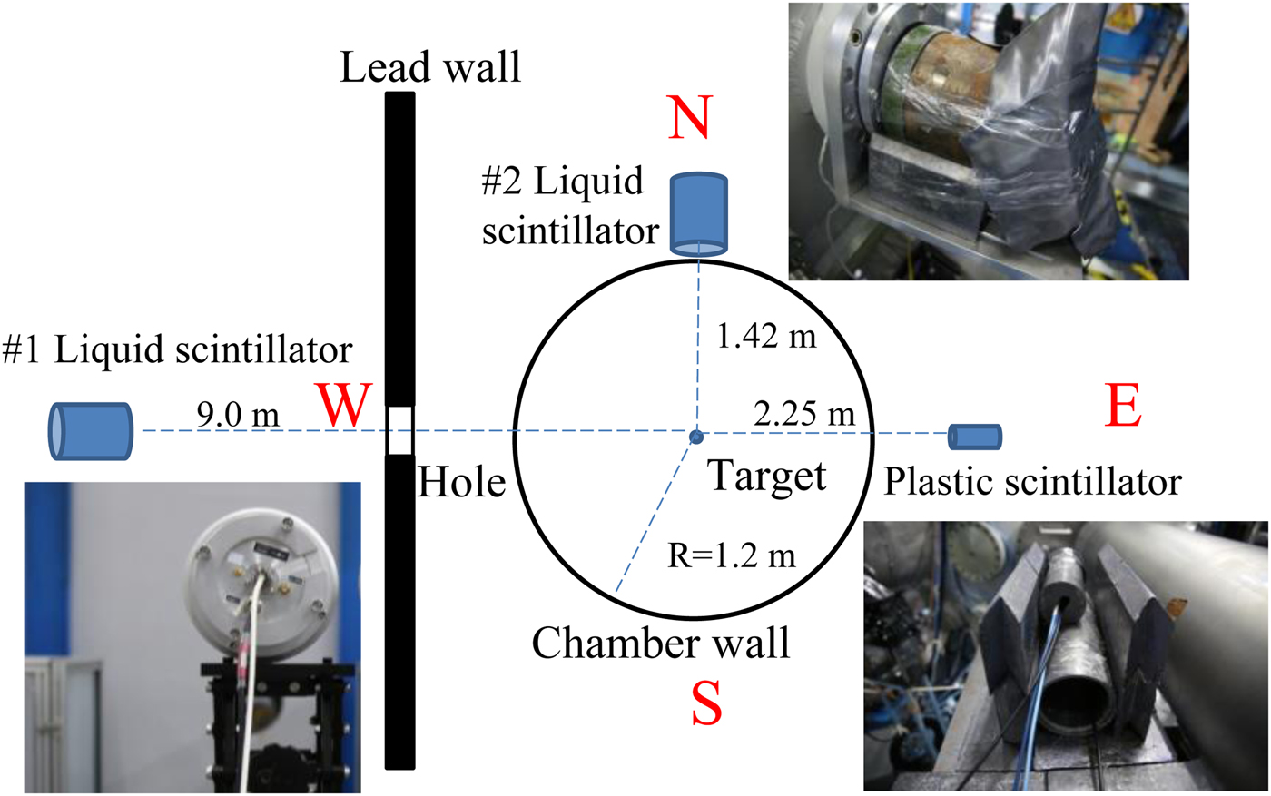
Fig. 1. Configuration of the neutron detectors.
Each nTOF detector was composed of a scintillator, a light guide and a microchannel plate PMT (MCP-PMT) connected with a digital oscilloscope, as shown in Figure 2(a). The liquid scintillator detector (Cui et al., Reference Cui, He, Liu, Dai, Yan, Lu, Li, Zhang, Hong and Gu2016) consisted of a cylindrical aluminum (Al) housing filled with a 14-cm-diameter, 10-cm-thick volume of liquid scintillator, which was coupled with a Photek PMT240 (Photek, 2013) with high gain (2 × 10⁵–106). This liquid scintillator (Lauck et al., Reference Lauck, Brandis, Bromberger, Dangendorf, Goldberg, Mor, Tittelmeier and Vartsky2009; Cui et al., Reference Cui, He, Liu, Dai, Yan, Lu, Li, Zhang, Hong and Gu2016) included a mixture of two fluorescent dyes, PPO and bis-MSB, dissolved in p-xylene and saturated with molecular oxygen. Oxygen was used as the quenching agent to suppress the afterglow caused by strong signals. Compared with those of conventional liquid scintillators for fast neutron detection, for example, BC501A (Patronis et al., Reference Patronis, Kokkoris, Giantsoudi, Perdikakis, Papadopoulos and Vlastou2007), this newly developed liquid scintillator has a much shorter decay time (<2 ns) and lower afterglow, which is well suited to our requirements for satisfactory time-of-flight (TOF) resolution of neutrons and γ rays in high-power laser–target interaction experiments.
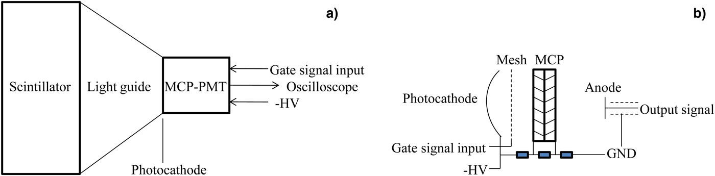
Fig. 2. Schematic diagram of the nTOF detector: (a) configuration of the scintillator detector and (b) simplified electrical schematic of the gated MCP-PMT.
The plastic scintillator is a 4-cm-diameter, 1-cm-thick volume of EJ232Q scintillator, mixed with 0.5% benzene as the quenching agent. A Hamamatsu gated R5916U MCP-PMT (Hamamatsu, 2014) with a 1-cm-diameter photocathode is coupled to the plastic scintillator with a light guide. The gain of the PMT can be adjusted by changing the biased voltage according to the operational range of the detector.
The MCP-PMT has a smaller volume with faster timing capability and higher current gain than the conventional PMT (Leskovar, Reference Leskovar1977). The general structure of the gated MCP-PMT used in this experiment is shown in Figure 2(b). The MCP has a two-stage chevron configuration, and there is a mesh gate between the photocathode and the MCP that becomes inactive when a positive pulse is applied to the gate. When the MCP-PMT is gated off, the photoelectrons from the photocathode cannot reach the MCP, and this configuration can be used to reduce the amplitude of the large background significantly. The time for gating can be adjusted by an induction gate controller and a delayed signal generator.
The sensitivities of the liquid scintillator detectors and the plastic scintillator detector biased at various voltages were calibrated with a compact dense plasma focus (DPF) neutron source (Burns et al., Reference Burns, Falacy, Hill, Thacher, Koehler and Davis1989; Geng, Reference Geng2007) and a 400-keV electrostatic accelerator (K-400) neutron source (Ruiz et al., Reference Ruiz, Leeper, Schmidlapp, Cooper and Malbrough1992, Reference Ruiz, Chandler, Cooper, Fehl, Hahn, Leeper, McWatters, Nelson, Smelser, Snow and Torres2012; Wu et al., Reference Wu, Li, Peng, Zhang and Guo2006) at the Institute of Nuclear Physics and Chemistry, China Academy of Engineering Physics. The uncertainty of the calibration using the DPF neutron source includes the fluctuations of statistical counting, the reading error of the neutron signal integral area, the source-to-detector distance, etc. The uncertainty in the calibration using the K-400 accelerator neutron source includes the scattered neutron background of the accelerator room, the solid angle of the detector, neutron yield monitoring (Zhu et al., Reference Zhu, Liu, Jiang, Lu, Wen, Wang and Lin2007), the γ-ray net counts, etc. The two kinds of calibration results are in agreement with each other. The errors on the sensitivity of DD and DT neutrons were 7 and 20%, respectively. The latter was much larger because the corresponding neutron source adopted for calibration was much weaker.
Experimental results and discussion
A typical signal obtained with the #1 liquid scintillator detector is shown in Figure 3. The peak time of the γ-ray signal is located at t = 238 ns, and the peak time of the neutron signal is at t = 621 ns. The distance from the #1 liquid scintillator detector to the target chamber center is 9 m, and this neutron signal corresponds to the primary DD neutrons according to the TOF method (Lerche and Remington, Reference Lerche and Remington1990), that is,  $t = 72.3l/\sqrt {E_{\rm n}} $, where t is the neutron flight time (in ns), l is the distance from the target to the detector (in m) and E n is the neutron energy (in MeV). Since the DT neutron yield is several orders lower than the DD neutron yield (Blue and Harris, Reference Blue and Harris1981), the DT neutron signal is too weak for detector #1 to acquire.

Fig. 3. Typical signals obtained by the #1 liquid scintillator detector.
Typical signals obtained with the #2 liquid scintillator detector are shown in Figure 4. According to the velocity of various products created by the laser–target interaction, the earliest arrived are the X rays (Azechi et al., Reference Azechi, Miyanaga, Stapf, Itoga, Nakaishi, Yamanaka, Shiraga, Tsuji, Ido and Nishihara1986; Glebov et al., Reference Glebov, Meyerhofer, Stoeckl and Zuegel2001), which come at t = 241 ns. This signal indicates that a lead layer of 3 cm is insufficient to shield all the hard X rays. The next signals are γ-ray signals (A, a), which are due to (n, γ) reactions with the target positioner and diagnostic instruments inside the chamber. Signals (B, b) correspond to DT neutrons, as the maximal energy of the neutron signals is 17.2 MeV (starting at t = 261 ns). The saturated signals (C, c) arrive 50 ns later than the X-ray signal, which corresponds to γ rays produced by DD neutrons interacting with the chamber wall. A large number of DD neutrons subsequently arrive and saturate the detector. The fast response of the scintillator and reasonable distance between the detector and the target allowed clear discrimination of the secondary DT neutron signals from the γ-ray signals introduced by DD neutron–chamber wall interaction. In this experiment, this distance should be less than 2.0 m to prevent DD neutron–chamber wall interaction-induced γ rays from masking the secondary DT neutron signals.

Fig. 4. Secondary DT neutron signals obtained by the #2 liquid scintillator detector.
The #2 detector was biased at −3200 V, and its sensitivity for DT neutrons was 0.24 ± 0.05 pC/n. The DT neutron yields of shots 511,039 and 512,040 were (3.3 ± 1.4) × 105 and (1.2 ± 0.5) × 106, respectively. The target and laser conditions of these shots were set unchanged, but in shot 512039, a laser beam switch was damaged. Hence, one of the eight ns beams delivered an energy of only 22 J to the capsule, and the spherical compression symmetry was violated. Note that the uncertainty was influenced not only by the uncertainty of the detector sensitivity as described in the section “Experimental configuration” but also by the solid angle, the reading error of neutron signal integral area and the statistical error of the number of detected DT neutrons. Together, these errors compose a total error of ~42%. Applying the gate, the MCP-PMT can be protected from damage induced by the burst of DD neutron signals.
According to glow curves reported previously (Lauck et al., Reference Lauck, Brandis, Bromberger, Dangendorf, Goldberg, Mor, Tittelmeier and Vartsky2009), the signal decays in various types of scintillators are very similar in the first 10–20 ns, and the benefit of the oxygen-enriched liquid scintillator with a ternary mixture of p-xylene as the solvent and PPO and bis-MSB as fluors is significant after ~50 ns. The time differences between the γ-ray peaks and the secondary neutron peaks in Figure 4 are <20 ns, so no benefit from the oxygen-quenched liquid scintillator is expected. For high-fuel-areal-density measurements in cryogenic implosions (Izumi et al., Reference Izumi, Lerche, Phillips, Schmid, Moran, Koch, Azechi and Sangster2003; Glebov et al., Reference Glebov, Forrest, Marshall, Romanofsky, Sangster, Shoup and Stoeckl2014), these spectrometers are located far enough from the targets (~10 m) to differentiate down-scattered neutrons from high primary-neutron backgrounds due to the sufficient resolution of nTOF spectroscopy.
The plastic scintillator detector was coupled to a gated MCP-PMT, and the gate of the PMT was switched on at t = 75 ns and switched off at t = 185 ns. As displayed in Figure 5, only the primary DD neutron signals were captured. Hard X rays created by the laser–target interaction and γ rays produced by DD neutron interactions with the chamber wall were completely suppressed by the gating. The detector was biased at −2700 V with the gain equal to 2.7 × 10⁴, and its sensitivity for DD neutrons was 0.015 ± 0.001 pC/n. The DD neutron yields of shot 512,039 and shot 512,040 were (1.65 ± 0.12) × 109 and (4.8 ± 0.34) × 109, respectively. The uncertainties were due mainly to the detector calibration and the statistical fluctuations, which were calculated to be ±7%.

Fig. 5. Primary DD neutron signals obtained by the plastic scintillator detector.
By deconvolving the DD nTOF spectrum (Lerche and Remington, Reference Lerche and Remington1990; Chen et al., Reference Chen, Zheng, Peng, Zhang, Ding, Chen, Chen and Wen2001), the ion temperatures were obtained with the formula T ion = (1.285 × Δt/D)2, where T ion is the ion temperature (keV), Δt is the full width at half maximum for the temporal spread of the nTOF spectrum (ns), and D is the distance between the target and the detector (in m). T ion was 1.9 ± 0.3 and 3.4 ± 0.5 keV for the two shots. The uncertainties were determined by the error in the Δt measurement, that is, σΔt, which was calculated to be 15% with the relations derived by Lerche and Remington (Lerche and Remington, Reference Lerche and Remington1990).
The implosion of D2-filled capsules was driven by the exploding of the glass shell and subsequent hydrodynamic compression of the fuel. In this process, the laser energy deposits in the glass so fast that the shell explodes. Approximately half of the shell mass explodes outward, and the remaining half implodes inward, which drives a shock wave into the fuel (Rosen and Nuckolls, Reference Rosen and Nuckolls1979; Ahlborn and Key, Reference Ahlborn and Key1981; Rosenberg et al., Reference Rosenberg, Zylstra, Séguin, Rinderknecht, Frenje, Johnson, Sio, Waugh, Sinenian, Li, Petrasso, McKenty, Hohenberger, Radha, Delettrez, Glebov, Betti, Goncharov, Knauer, Sangster, LePape, Mackinnon, Pino, McNaney, Rygg, Amendt, Bellei, Benedetti, Hopkins, Bionta, Casey, Divol, Edwards, Glenn, Glenzer, Hicks, Kimbrough, Landen, Lindl, Ma, MacPhee, Meezan, Moody, Moran, Park, Remington, Robey, Rosen, Wilks, Zacharias, Herrmann, Hoffman, Kyrala, Leeper, Olson, Kilkenny and Nikroo2014). Both the shock and the imploding pusher shell compress and heat the D2 gas, creating a “hot spot” at the center of the fuel. The compressed fuel areal density can be obtained with the yield ratio of secondary DT neutrons to primary DD neutrons (i.e., Eq. (6)), and 〈ρR〉fuel for shot 512,039 and shot 512,040 were 1.9 ± 0.9 and 2.4 ± 1.1 mg/cm2, respectively. The error in 〈ρR〉fuel was a result of DT and DD neutron errors.
The initial mass density of the 15 atm D2 gas was 2.68 mg/cm3, and the initial fuel radius (R f0) was 0.0223 cm; thus, the initial fuel areal density (〈ρR f0〉) before implosion was 0.06 mg/cm2. The implosion convergence ratios, that is, the initial fuel radius to the final thermonuclear radius, were 5.6 and 6.3 for the two shots.
Since the experiment described above involves a pure implosion without short-pulse (ps or fs) lasers, the γ-ray background was not very strong. As shown in Figure 4, the signals of background γ rays (B, b) were weaker than the secondary neutron signals, and both were within the linear range of the detector and scope; thus, the advantage of the fast-decaying characteristic of the oxygenated liquid scintillator was not clearly shown. Hence, we further tested the neutron detector in an integrated FI experiment with a ps laser.
The FI experiment was also performed at the SG-II-UP laser facility. A deuterated polystyrene (CD) shell (400 µm inner diameter, 50 µm thickness) with an embedded hollow golden cone was imploded by soft X rays transformed from the eight long-pulse beams (351 nm, 2 ns) with a total energy of 20 kJ ablating the Au hohlraum. A 10-μm CH coating was used to suppress the neutrons generated from the beam–target interaction at the interface of the CD shell and the expanding Au plasma bubbles generated on the hohlraum wall (Shan et al., Reference Shan, Cai, Zhang, Tang, Zhang, Song, Bi, Ge, Chen, Liu, Wang, Yang, Qi, Tian, Yuan, Zhang, Yang, Jiao, Cui, Zhou, Cao, Zhou, Gu, Zhang, Zhu and He2018). At the maximum compression time, a short-pulse laser (1053 nm, 3 ps) with an energy of 150 J was injected into the inner tip of the hollow golden cone to generate fast electrons and then heat the core plasma.
The fast electrons generated a large amount of γ rays through Bremsstrahlung processes. The main diagnostic of the neutron yield was the #2 liquid scintillator detector located 3.0 m from the target, which was shielded with a 10-cm layer of lead in front and 5 cm of surrounding lead. The detector was biased at −3800 V, and its sensitivity for DD neutrons was 1.84 ± 0.13 pC/n. The solid line in Figure 6 is the signal obtained in shot 407058. The γ-ray (200 ns) signal was suitably suppressed by the MCP-PMT gating. The gate was opened at 250 ns, and a small scintillator decay tail was observed that arose from the low afterglow of the oxygenated liquid scintillator. A clear DD neutron signal that started at 330 ns was captured, and the neutron yield was (7.4 ± 0.8) × 105. The uncertainty is due to the error of the sensitivity, the attenuation of lead shielding and the statistical error. When the gate was removed in shot 407,056 (the target and the laser parameter are the same as in shot 407,058), the detector was saturated by intense γ rays.
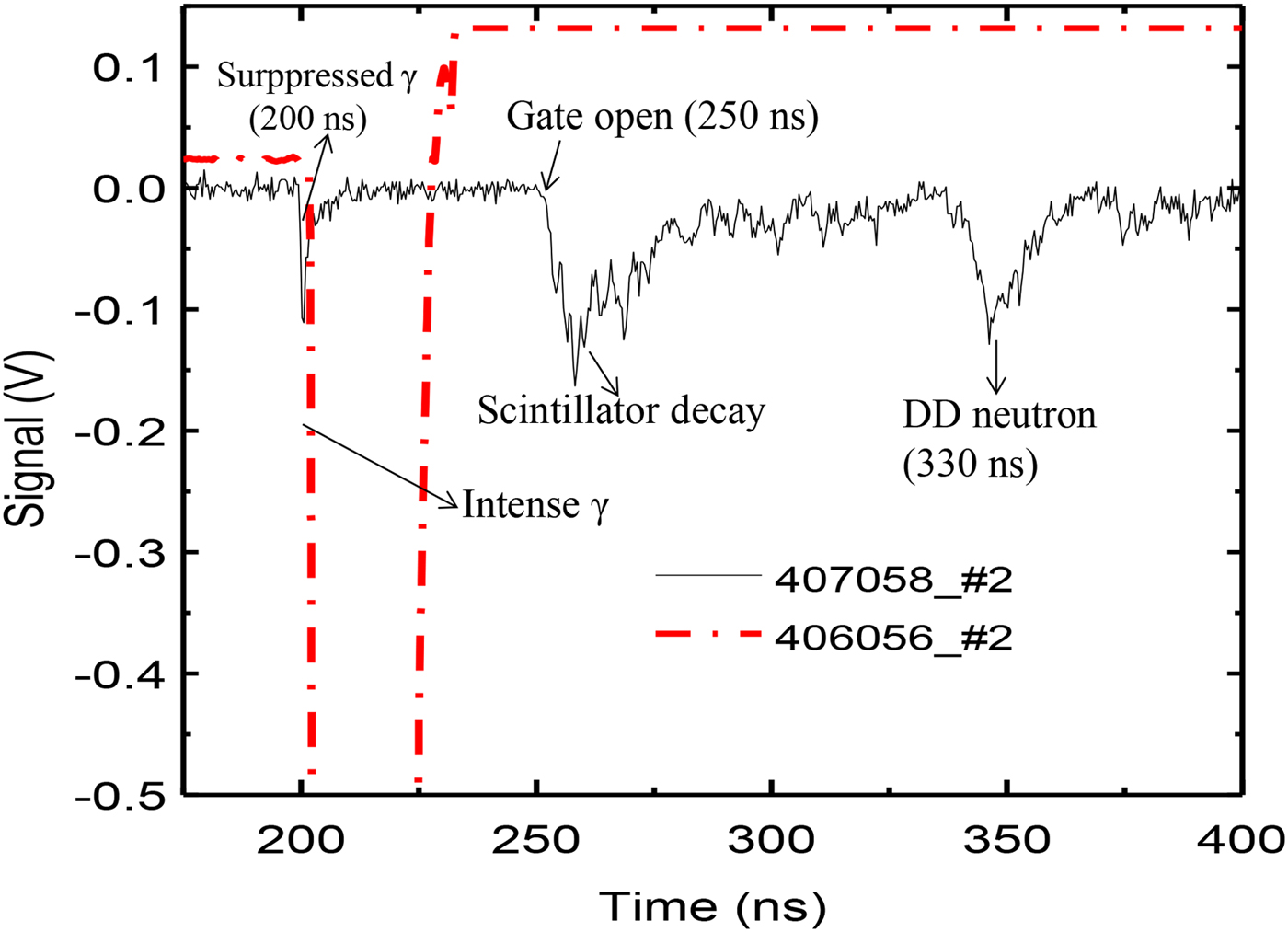
Fig. 6. Signals obtained by the #2 liquid scintillator detector in the integrated FI experiment.
High-resolution nTOF spectrometers were installed at the SG-II-UP laser facility, providing reliable measurements of the neutron yield, ion temperature, compressed fuel areal density, and implosion convergence ratio. These nTOF spectrometers can differentiate the thermonuclear neutrons from the neutrons by beam-fusion, (p, n) and (γ, n) reactions in the experiments with an ultraintense short-pulse laser and can distinguish down-scattered neutrons from strong primary-neutron backgrounds in high-fuel-areal-density cryogenic implosions.
Simulation results and discussion
The hydrodynamic instability and fuel-shell mixing can increase the energy loss of primary-fusion-produced tritons (Séguin et al., Reference Séguin, Li, Frenje, Hicks, Green, Kurebayashi, Petrasso, Soures, Meyerhofer, Glebov, Soures, Meyerhofer, Glebov, Radha, Stoeckl, Roberts, Sorce, Sangster, Cable, Fletcher and Padalino2002; Kurebayashi et al., Reference Kurebayashi, Frenje, Séguin, Rygg, Li, Petrasso, Glebov, Delettrez, Sangster, Meyerhofer, Stoeckl, Soures, Amendt, Hatchett and Turner2005). If the triton energy is significantly decreased, the cross-section of the DT reaction σ increases and cannot be regarded as a constant. The 〈ρR〉fuel obtained by the yield ratio method according to Eq. (5) would then be higher than the actual value. To verify the applicability of the yield-ratio method for low-〈ρR〉 implosions, we performed a one-dimensional (1D) hydrodynamic simulation with Multi-1D (Ramis et al., Reference Ramis, Schmalz and Meyer-ter-Vehn1988), which is a 1D hydrodynamic software package incorporating coupled thermal radiation transport, heat conduction, and several energy deposition mechanisms: laser beams, ion beams, and fusion-produced α particles.
The direct drive compression of the D2 gas was simulated in spherical coordinates based on Multi-1D. The laser parameters are as follows: the total energy is 8 kJ, the energy concentration is 50%, λ = 351 nm, the pulse duration is 1 ns, and the average laser intensity is 6.2 × 10¹⁴ W/cm2. The capsule has an outer diameter of 450 µm and a SiO2 glass wall of 2 µm and is filled with D2 gas with a density of 2.68 mg/cm3.
Multi-1D simulation results are shown in Figure 7. The streamlines of the implosion layer are illustrated in Figure 7(a). The thin SiO2 shell is ablated away, driving a strong shock wave into the D2 gas. This shock compresses the D2, converges at the center and then rebounds. The rebounding shock compresses the gas once again, and a shock-phase is produced. The D2 fuel reaches peak compression at 0.51 ns, and the minimal compressed fuel radius is 15 µm. The time history of the D2 fuel density is shown in Figure 7(b), and the maximal density at the peak compression time (0.51 ns) is 9.315 g/cm3. The simulation prediction for the fuel areal density 〈ρR f〉 is 3 mg/cm2 at 0.51 ns according to Eq. (1), which is consistent with our experimental result of shot 512,040 (2.4 ± 1.1 mg/cm2) with the same target and laser parameters, which indicates that the yield-ratio method is suitable for estimating 〈ρR〉 for low-fuel-areal-density implosions.
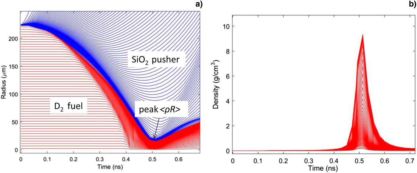
Fig. 7. Multi-1D simulation results: (a) streamlines of the implosion layer and (b) density distribution of D2 fuel.
Conclusion
High-resolution nTOF spectrometers have been developed at the SG-II-UP laser facility to measure the neutron yield and areal density of imploded deuterium-filled capsules. Quenched liquid scintillator detectors with a fast response and gated ultrafast plastic scintillator detector were separately deployed at suitable distances to measure the DT and DD neutrons. A clear secondary neutron signal was obtained, and the compressed fuel areal density was obtained with the yield-ratio method, which agrees well with the Multi-1D simulations. The results verify that the yield-ratio method is well suited to estimate 〈ρR〉 in low-〈ρR〉 implosion experiments. In an integrated FI experiment with a ps laser having a strong γ-ray background, the gated liquid scintillator detector obtained a clear signal of DD neutrons owing to the low afterglow of the oxygenated liquid scintillator.
Such nTOF spectrometers can be used to diagnose the ion temperature, areal density and confinement time of compressed plasma in FI experiments and can also distinguish the thermonuclear neutrons from the beam-fusion neutrons and the (p, n) and (γ, n) neutrons in experiments with ultraintense short-pulse lasers.
Author ORCIDs
Bo Cui, 0000-0003-0991-3255.
Acknowledgements
The authors gratefully acknowledge the SG-II-UP facility staff for operating the laser facility in the experiment. Bo Cui would like to thank Yuchi Wu for fruitful discussions. This work was supported by the Science Challenge Project (no. TZ2018005) and the National Natural Science Foundation of China (no. 11375159).


