


1. INTRODUCTION: GENERAL BACKGROUND, MOTIVATION AND APPLICATIONS
Numerous applications indicate that laser-matter interaction is technologically important (Hoffmann et al., Reference Hoffmann, Blazevic, Rosmej, Roth, Tahir, Tauschwitz, Udrea, Varentsov, Weyrich and Maron2005). In particular, the interaction of intense laser beams with plasmas is highly relevant to laser fusion (Miller et al., Reference Miller, Moses and Wuest2004), material science and medicine (Gamaly et al., Reference Gamaly, Rode, Luther-Davies and Tikhonchuk2002), and nanoparticles generation (Eliezer et al., Reference Eliezer, Eliaz, Grossman, Fisher, Gouzman, Henis, Pecker, Horovitz, Fraenkel, Maman, Ezersky and Eliezer2005). The interferometric diagnostics was established as a technique to probe dense plasmas using optical wavelength laser beams (Attwood et al., Reference Attwood, Sweeney, Auerbach and Lee1978). A large electric field can be generated in plasma by high power lasers and used to accelerate electrons (Tajima & Dawson, Reference Tajima and Dawson1979; Steinke et al., Reference Steinke, Henig, Schnurer, Sokollik, Nickles, Jung, Kiefer, Horlein, Schreiber, Tajima, Yan, Hegelich, Meyer-ter-Vehn, Sandner and Habs2010; Shoucri et al., Reference Shoucri, Lavocat-Dubuis, Matte and Vidal2011).
One of the important phenomena is plasma generation near a target surface by the impingement of laser radiation of moderate power density (106–1010 W/cm2) focused onto a very small area. Such plasmas are used for target surface treatment (Tsue & Redman, Reference Tsue and Redman2000; Fernandez et al., Reference Fernandez, Hegelich, Cobble, Flippo, Letzring, Johnson, Gautier, Shimada, Kyrala, Wang, Wetteland and Schreiber2005), thin film deposition (Anisimov et al., Reference Anisimov, Bauerly and Luk'yanchuk1993; Gamaly et al., Reference Gamaly, Rodea and Luther-Davies1999; Singh & Narayan, Reference Singh and Narayan1990; Shukla & Khare, Reference Shukla and Khare2010), high-energy atomic beam generation (Zheng et al., Reference Zheng, Huang, Shaw and Kowk1989), laser welding (Moscicki et al., Reference Moscicki, Hoffman and Szymanski2006), laser beam machining (Dubey & Yadava, Reference Dubey and Yadava2008), and ion beam generation (Schaumann et al., Reference Schaumann, Schollmeier, Rodriguez-Prieto, Blazevic, Brambrink, Geissel, Korostiy, Pirzadeh, Roth, Rosmej, Faenov, Pikuz, Tsigutkin, Maron, Tahir and Hoffmann2005).
Several phenomena occur during laser-target interaction (LTI). When the laser pulse is absorbed by the target, energy is converted into thermal and mechanical energy, ablating the target. When the laser pulse is absorbed by the vapor, energy is converted into thermal energy of the vapor particles, and then into plasma formation. Then the laser radiation will interact with the generated plasma. Understanding the physics of energy conversion is useful for choosing the laser and target characteristics suitable for different applications, taking into account ablation. This understanding can be achieved by theoretically modeling laser plasma generation and plasma expansion. The models should be based on experimental studies of the laser interaction phenomena. Below the state of plasma measurements is discussed to formulate the main problem of moderate power laser interactions with metallic targets and the results are used for laser plasma modeling.
2. REVIEW OF EXPERIMENTAL RESULTS and MODELS
2.1. Methods and Measurements
A laser pulsed beam with 6-ns pulse durations 3.2 mJ energy impinged on an Al target and modified it. Using scanning electron microscopy Henc-Bartolic et al. (Reference Henc-Bartolic, Boncina, Jakovljevic, Pipic and Zupanic2008) observed that molten droplets with radii between 0.1 and 0.5 µm, Al vapor and surface craters of about 30 µm depth were formed after 50 laser pulses. The electron temperature of the Al plasma was estimated as 1.4 eV, using spectroscopic data and that the laser energy was mostly absorbed by the plasma particles. The plasma produced by a pulsed nitrogen laser beam (6 ns, 9 mJ) impinging on a Ti target was studied spectroscopically by Henc-Bartolic et al. (Reference Henc-Bartolic, Andreic and Kunze1994). It was found that the electron density was n e~(1.5–3) × 1018 cm−3 and that Stark broadening is the dominant broadening mechanism. The electron temperature T e measured from the relative intensities of two Ti spectral lines in vacuum was approximately 2.7 eV.
Time- and space-resolved spectra were recorded by Hermann et al. (Reference Hermann, Thomann, Leborgne and Dubreuil1995) to investigate the plasma formed from 20 ns pulsed excimer laser irradiation of Ti targets. The laser intensity was varied from the vaporization threshold at 25 MW/cm2 up to 500 MW/cm2, which generated plasma. T e at distance 2 mm from the target decreased with time, from 2–3 eV at 150 ns after the laser pulse, to 1.5 eV at 300 ns. At fixed time of 100 ns after the laser pulse, density n e decreased with distance, from 1018 cm3 at 0.5 mm to 1017 cm3 at 2 mm, as measured using the Stark broadening of Ti atom and ion lines. When the power density increased from 25 to 500 MW/cm2, the directed ion velocity increased from 2 × 10⁵ to 2 × 106 cm/s.
Chang and Warner (Reference Chang and Warner1996) used a Cu vapor laser (CVL) and varied the intensity from 0.1 to 10 GW/cm2 to investigate the parameters of plasma generated from Al and carbon steel targets. Schlieren images were captured by a charge-coupled device. A narrow-band filter centered at the probe laser wavelength was used to block the plume radiation and scattered CVL light. The measured speed (3–20) × 105 cm/s was used to determine vapor density, temperature, and pressure during the end of the CVL pulse through the hydrodynamic relations describing adiabatic shock expansion and Knudsen-layer jump conditions. It was found that T e was 1–2 eV and n e = 1020–1021 cm−3. These data correlated with published measurements even though the reverse approach was uncertain.
The energy distribution of ions ejected from solid and liquid Si and Ge and from solid Cu targets by a high-fluence (1–8) J/cm2 excimer laser was determined by analyzing the time of flight (TOF), by measuring the current pulse delay of ions overcoming an adjustable electrostatic potential barrier applied before a detector (Franghiadakis et al., Reference Franghiadakis, Fotakis and Tzanetakis1999). For both solid and liquid targets, the ion energies were found on the order of 100 eV per ion charge and depended little on the laser fluence.
Abdellatif and Imam (Reference Abdellatif and Imam2002) determined the spatial distribution of T e using Boltzmann plots of Al II lines and the spatial profile of n e using Stark broadening, produced by a 7 ns pulse laser with wavelengths 1064, 532, and 355 nm. When the laser wavelength was 1064 nm, T e~1.17 eV at the target surface, passed maximum (6.3eV), and it increased gradually to 4.2 eV at a distance of 500 mm from the target surface and then decreased with distance to about 1 eV. When the laser wavelength was 355 nm, maximum T e was about 5.7 eV and n e = (0.85–0.35) × 1018 cm−3. Rieger et al. (Reference Rieger, Taschuk, Tsui and Fedosejevs2003) investigated the emission Si and Al plasmas produced by a KrF laser with 10 ps pulse and power densities (0.05–50) GW/cm2, and also with 50 ps pulse and power densities (10–104) GW/cm2. It was shown that 50 ps, 100 GW/cm2 pulses generated Al plasma with n e~1022 cm−3, T e~14 eV, while 10 ns, 0.5 GW/cm2 pulses produced 1020 cm−3 and ~2.4 eV.
A 7 ns pulsed Nd:YAG laser producing a 52 mJ, 335 nm, 1010 W/cm2 beam was irradiated on a Cu target in vacuum and Ar (Hafez et al., Reference Hafez, Khedr, Elaksher and Gamal2003). T e was determined by a Boltzmann plot and n e by Stark broadening. Also a single Langmuir probe was located 3.5 mm from the target. In vacuum, T e increased from 1.6 eV at the surface to 3.8 eV at a distance of 2 mm from the surface, and then decreased, reaching 0.6 eV at 10 mm. The plasma velocity was found as 5.3 × 105 cm/s. The electron density was n e~1.4 × 1016 cm−3 at the surface and decreased by more than one order of magnitude at a distance of 10 mm from the target.
The plasmas produced by a 200 mJ, 8 ns pulse in air on a target from ~60% Cu, ~40% Zn brass alloy was studied spectroscopically (Corsi et al., Reference Corsi, Cristoforetti, Giuffrida, Hidalgo, Legnaioli, Palleschi, Salvetti, Tognoni and Vallebona2004). It was reported that n e was 1016–1018 cm3 and T e 0.7–1.2 eV. Aguilera et al. (Reference Aguilera, Bengoechea and Arago.2004) studied plasma induced by a (3.5–4.5) GW/cm2, 4.5 ns, laser beam in atmospheric pressure air and Ar and focused onto a Fe target, and determined the temporal and spatial distributions of T e and n e and neutral atom density. In air, the Fe emissivity and atom density were maximized when the focal plane of the lens was placed 10 and 12 mm, respectively, below the sample surface, whereas higher temperature (1 eV) was obtained when the focus was 5 mm below the surface and decreased for deeper focusing positions. This behavior is explained by plasma shielding at high laser irradiance. The emission intensity in Ar was about twice of the intensity in air due to higher temperature in Ar. Also, a maximum of the emission intensity was found for both gases at a focus distance of ~10 mm.
Laser generated metallic plasma was widely investigated by Torrisi and co-authors, and the details of their methods were described recently (Margarone et al., 2008; Torrisi et al., Reference Torrisi, Caridi, Margarone and Borrielli2008a, 2008b). They used a Nd:Yag laser with a 3–9 ns pulse and fluence of (0.1–9.3) J/cm2. Electrostatic ion energy analyzers and the TOF technique were used to measure the ion energy and charge state distributions. The mass loss per pulse was obtained by measuring the crater depth profile. The radiation emission spectrum, T e and n e were investigated by optical spectroscopy using a charge-coupled device camera. They found, for metal targets with a wide range of thermophysical properties, that the ion distribution function was a shifted Maxwellian distribution, which depended on laser fluence, and that the energy shift increased linearly with the ion charge. For carbon it was about 65 eV/charge (Torrisi et al., Reference Torrisi, Caridi, Margarone, Picciotto, Mangione and Beltrano2006) and for Si about 300 eV/charge, with ion charge from +1 to +4 at 150 mJ laser energy (Torrisi et al., Reference Torrisi, Caridi, Margarone and Borrielli2008a, Reference Torrisi, Caridi, Margarone and Borrielli2008b). Using the maximal energy ion distribution shift the estimated singly charged ion velocity for carbon was 2.8 × 106 cm/s and for Si was 4.5 × 106 cm/s. The energy shift increase with the ion charge was explained assuming that an electrostatic field is present within a Debye length similarly with that electric field occurred for high intensity fs and ps laser pulse irradiation.
For Ta, the ion energy was higher, about 200 eV/charge at 30 J/cm2 and about 600 eV/charge state at 100 J/cm2 (Torrisi et al., Reference Torrisi, Gammino, Ando and Laska2002). The average width of the distribution indicated a relatively large ion temperature, (7–26) × 105K, i.e., about 60–200 eV, while the average plasma velocity was reported as (0.7–1.4) × 106 cm/s. Later for Ag plasma spectroscopic was obtained T e~5 eV and n e~2 × 1016 cm−3 (Margarone et al., 2008). Similarly shifted Maxwellian ion distributions were observed by Bleiner et al. (Reference Bleiner, Bogaerts, Beiloni and Nassisi2007). The average width of the distribution indicated ion temperature depended on the target material: 18, 27, 30, and 45 eV for Al, Fe, Sn, and Zn, respectively.
Torrisi et al. (Reference Torrisi, Ciavola, Gammino, Ando and Barna2000, Reference Torrisi, Ando, Ciavola, Gammino and Barna2001) measured the target mass loss from the craters by weighing the targets before and after irradiation by 1000 pulses of 9 ns, 875 mJ, and found 0.25, 0.51, 0.55, and 10.5 µg/pulse for Cu, Al, Ni, and Pb, respectively. Another group of materials, Au, Ti, W, and Ta, had higher mass loss (except for Pb), 0.8–1 µg/pulse. A linear dependence of mass loss on fluency in range of 1–6 J/cm2 was measured for Al, Cu, and Ta targets (Caridi et al., Reference Caridi, Torrisi, Margarone, Picciotto, Mezzasalma and Gammino2006). Kasperczuk et al. (Reference Kasperczuk, Pisarczyk, Kalal, Martinkova, Ullschmied, Krousky, Masek, Pfeifer, Rohlena, Skala and Pisarczyk2008) showed that the craters have a semi-toroidal shape when the laser was focused inside of the target, and when the laser was focused at the front position they resemble a hemisphere.
Zeng et al. (Reference Zeng, Mao, Mao, Wen, Greif and Russo2006) spectroscopically measured T e and n e in plasma produced by ns laser impinging on Si target with a flat surface or cavity. T e was 3eV, about 4eV and n e was about 5 × 1018 cm−3, (1–3) × 1019 cm−3 with flat surface and cavity, respectively. T e and n e spatial distributions were uniform up to 1.5 mm from the target surface. The plasma expanded at a velocity of 5 × 105 cm/s.
The spatial evolution of T e and n e in plasma generated on SiC samples by a Nd:YAG laser beam at wave length of 1064 nm, pulse width of 10 ns, and power of 0.2–2 GW, was spectroscopically studied by Chen et al. (Reference Chen, Liu, Yanga, Zhao, Sun, Qi, Chenc and Xu2008). They found that n e decreased from 1.8 to 0.73 × 1017 cm−3 and T e from 1.4–1.7 to 1 eV with distance from the target up to 9 mm. In the region between 3–9 mm, n e fluctuated and T e decreased slowly. Further investigations of these authors determined the T e and n e dependence on the time after the pulse (Chen et al., Reference Chen, Liu, Zhao, Chen and Man2009a, Reference Chen, Liu, Zhao and Sun2009b; Sun et al., Reference Sun, Chen, Li, Qi, Zhao and Liu2008). It was shown that T e substantially and n e moderately decreased with time in range of 50–600 ns. For example, at 1 mm from the target surface, T e decreased from 3.3 to 1.75 eV and n e decreased from 2.6 × 10¹⁷ to 2.25 × 1017 cm−3 at 50 and 400 ns respectively after the laser pulse. T e and n e had maxima at about 2 mm from the target surface.
Cristoforetti et al. (Reference Cristoforetti, Lorenzetti, Benedetti, Tognoni, Legnaioli and Palleschi2009) spectroscopically observed that n e increased from 0.7 × 10¹⁶ to 2 × 1017 cm−3 and T e from 0.85 to 1.15 eV when the irradiance of a Nd:YAG laser beam of Al target increased from 3 × 10⁸ to 5 × 10⁹ Wcm2. Ablated plasma flow from a liquid Ga-In target was studied with laser power density 1 GW/cm2 and pulse duration 2.7 ns (Popov et al., Reference Popov, Panchenko, Batrakov, Ljubchenko and Mataibaev2011). The average ion energy and the directed ion velocity were measured using a mass-energy and TOF methods, respectively. The found energy of about 400 eV, indicating that there was an electrostatic field in the plasma plume. However, a relatively low velocity of about 3 × 105 cm/s was measured. Measured characteristic plasma parameters published in last decades are summarized in Table 1.
Table 1. The methods and measured characteristic plasma parameters (ion velocity and energy, electron temperature and density) depending on laser type, power, pulse duration and spot area in experiments with laser irradiation of the different target materials.

2.2. Laser Plasma Plume Models
Material ablated from the target from the impingement of a laser beam expands away from the surface in form of a plasma jet. Jet expansion into vacuum is described by the hydrodynamaic equations, expressing the conservation of mass, momentum, and energy. Gamaly et al. (Reference Gamaly, Luther-Davies, Kolev, Madsen, Duering and Rode2005) showed that with ps pulses the ablation threshold of laser irradiation in air is significantly lower than in vacuum. Plasma formation by the impingement of nanosecond (3–7) J/cm2 pulsed laser beams on Cu, Ba, and Y targets was modeled by Singh and Narayan (Reference Singh and Narayan1990). The assumed equilibrium, with T e equal to the heavy particle temperature T, isothermal expansion during the pulse action and adiabatic plasma expansion after the pulse. The dynamics of thin film laser deposition was obtained using the time evolution of the calculated plasma velocity and measured T e.
Bogaerts et al. (Reference Bogaerts, Chen, Gijbels and Vertes2003) and Chen et al. (Reference Chen and Bogaerts2005) proposed a one-dimensional transient system of equation for equilibrium plasma and Moscicki et al. (Reference Moscicki, Hoffman and Szymanski2006) proposed a two-dimensional approach. Non-equilibrium (i.e., T e ≠ T) plasma expansion was simulated by Itina et al. (Reference Itina, Hermann, Delaporte and Sentis2002). A three-dimensional computer code was used by Wang and Chen (Reference Wang and Chen2003) to solve the hydrodynamic governing equations, to study the plasma plume characteristics in laser welding for iron vapor in an ambient gas. The temperature, vapor, and gas velocity as boundary conditions at the target were used as parameters. An important part of LTI study is to correctly define the temperature dependent boundary conditions at the target-plasma interface. A model of laser ablation in an ambient gas taking into account the phenomena of target-vapor interaction was proposed by Gusarov et al. (Reference Gusarov, Gnedovets and Smurov2000) and Gusarov and Aoki (Reference Gusarov and Aoki2005). A weakly ionized vapor was considered, and the given plasma pressure at the target-plasma kinetic boundary was used as a parameter, assuming plasma equilibrium (i.e., T e = T).
Cathode spot theory (Beilis, Reference Beilis2001) was modified for current-less laser generated plasma flow (Beilis, Reference Beilis2006). This model takes in account non-equilibrium plasma flow and a jump of plasma parameters in the Knudsen layer, at the solid surface-plasma interface self-consistently. The mechanism of near-target laser plasma generation and flow using the kinetics of target vaporization, plasma heating and atom ionization was considered self-consistently in a mathematical model without arbitrary given parameters (Beilis, Reference Beilis2007).
2.3. Review Summary
When the laser power density exceeds 108 W/cm2, the plasma was produced with broad ion kinetic energy distributions. Furthermore, when multiply charged ions are detected, it was found that their most probable kinetic energy increases linearly with the ion charge. This energy reaches few hundred eV per ion charge, and was identified with a correspondingly large potential drop in the plasma, which was not always correlated with the moderate plasma velocities (5–20) × 105 cm/s that were observed by TOF. Also, the electron temperature was usually low, 1–2 eV, and the direct spectroscopic measurements never exceeded 5–6 eV, while the measured average width of the ion velocity distribution function corresponded to relatively large plasma temperatures, reaching few tens eV depending on target material and laser fluence.
While these measured plasma parameters were briefly explained in the discussions in the experimental papers, they only considered separate phenomena and were usually based on comparison with other observations. The mechanism of ion acceleration for high power (>1014 W/cm2) laser impingement was used to explain the ion energy measured by the moderate laser power irradiation. Why the relatively large measured ion energies were not correlated with the low spectroscopically measured electron temperatures was not explained. In the theoretical works, the calculated results for moderate power density were obtained using some arbitrary parameters. Mostly the calculated results agreed with the measured low electron temperatures and plasma velocities. However, multi-charged (>2) ion generation and the ion energy dependence on charge in the expanding plasma was not considered. Thus, understanding of the measured results requests to consider the LTI as mutually dependent phenomena.
2.4. Objective and Organization
The objective of this paper is to clarify the tractability of moderate energy LTI measurements considering the coupled physical phenomena determined the produced laser plasma parameters as ion energy, plasma temperature, etc. To this end, the physics of laser ablation and plasma generation will be considered, taking into account the kinetics near the target-plasma interface, the hydrodynamics of plasma flow based on existing mechanisms of plasma acceleration, and using a previously developed self-consistent approach to LTI. Therefore the phenomena description will be detailed separately (Section 3) to base the developed plasma model for LTI. Thus, LTI is studied by analyzing target vaporization (Section 3.1), considering vapor breakdown mechanisms (Section 3.2), sheath formation (Section 3.3), electron emission (Section 3.4), and mechanism of plasma heating (Section 3.5). Section 4 models the plasma expansion and Section 5 describes the existing mechanisms of plasma acceleration. The application of laser plasma model and calculating results will be presented in Section 6. The calculated results and the possible nature of ion energy distribution and the energy dependence on ion charge by LTI will be discussed and summarized in Section 7.
3. NEAR-TARGET PHENOMENA
The pulsed laser ablation and plasma formation is complex and various phenomena occur. Below these phenomena are analyzed separately using the known data to their involving self-consistently by the laser plasma modeling.
3.1. Target Ablation
Let us consider the target evaporation and furthermore heavy particle flow. Assuming that the rates of atom condensation and evaporation were equal, Langmuir and Mackay (Reference Langmuir and Mackay1914) obtained that evaporated atomic flux density W L into vacuum is determined by the equilibrium vapor pressure P as W L = P/(2πmkT 0)0.5, where m is the atom mass, k is the Boltzmann's constant, and T 0 K is the surface temperature. However, for relatively large T 0, collisions produce a non-equilibrium layer of several mean free path lengths where the atoms are returned back to the surface, and therefore the net rate of material evaporation is less than that into vacuum. Knudsen (Reference Knudsen1915) showed that a kinetic treatment is required due to non-equilibrium effects. The particle distribution function approaches equilibrium at the external boundary of the Knudsen layer or atom relaxation zone. Collisions in the vapor force the distribution function (DF) toward a Maxwellian form. Thus two regions appear near the surface: (1) a non-equilibrium region with rare collisions near the target surface and (2) a collision dominated region with hydrodynamic vapor flow. A kinetic approach was used to solve the Boltzmann equation and thus to determine the flow density n, temperature T, and flow velocity u in the non-equilibrium region. These parameters at the external boundary of the Knudsen layer determine the boundary condition for the hydrodynamic flow along a path from the surface. Bhatnagar et al. (Reference Bhatnagar, Cross and Krook1954) modeled the collision term in the Boltzmann equation assuming a constant collision time τ, called the relaxation model, in form
where v is the velocity vector, r is the spatial coordinate, f is the DF, f 0 is the local equilibrium distribution function. A steady state one-dimensional problem was considered when the characteristic time of the hydrodynamic parameter set is smaller than the characteristic time of change the heat flux to the surface (Anisimov et al., Reference Anisimov, Imas, Romanov and Khodyko1971):
Boundary conditions:
![\,f_0=n_0 \left(\displaystyle{m \over {{\rm \pi} 2kT_0 }}\right)^{3/2} \exp \left[- \displaystyle{{mv^2 } \over {2kT_0 }}\right]\quad v \gt 0 \quad \hbox {at} \quad x=0 \eqno\lpar 3\rpar](https://static.cambridge.org/binary/version/id/urn:cambridge.org:id:binary:20151021100151072-0360:S0263034612000183_eqn3.gif?pub-status=live)
![\,f_\infty=n_\infty \left(\displaystyle{m \over {{\rm \pi} 2kT_\infty }}\right)^{3/2} \exp \left[- \displaystyle{m \over {2kT_\infty }}\lpar \lpar v_x - u\rpar ^2+v_y^2+v_z^2 \rpar \right].](https://static.cambridge.org/binary/version/id/urn:cambridge.org:id:binary:20151021100151072-0360:S0263034612000183_eqnU1.gif?pub-status=live)
at the equilibrium side (∞). The evaporated atoms have a half-Maxwellian DF (f 0) with the surface temperature and density, which is the boundary condition at the evaporated surface x = 0. Eqs. (2) and (3) were solved by different approaches. Anisimov (Reference Anisimov1968) considers the non-equilibrium layer as a discontinuity surface in the treatment of expanded vapor in LTI similar to the shock wave problem. Assuming sonic velocity u = u sn, i.e., Mach number M = 1, at the external boundary of the Knudsen layer he obtained an evaporated atom flux of about 0.82 W L. Fisher (Reference Fisher1976) solved the kinetic problem using the BGK approach and obtained that the rate of evaporation into an infinite half-space is about 0.85 W L.
Laser-induced vaporization of Al and iron targets in air at atmospheric pressure was studied by Aden et al. (Reference Aden, Beyer and Herziger1990). It was shown that u = u sn is an upper bound for the vapor velocity and for an absorbed intensity the vaporization is independent of the ambient gas. However, in general, the vaporization depends on the ambient pressure, which determines the flow properties in the Knudsen layer. Electrode vaporization into electrical arc plasma, taking into account also electron emission, was treated kinetically by Beilis (Reference Beilis1982, Reference Beilis1985, Reference Beilis1986). The definition of plasma flow as a non-free (impeded) when M < 1 and as free into vacuum when M = 1 was introduced by Beilis (Reference Beilis1985, Reference Beilis1986). A strongly impeded mass flow was obtained in cathode evaporation in a vacuum arc due to energy dissipation in the dense plasma. The condition for impeded plasma flow was studied in the case of Teflon propellant in thrusters by Keidar et al. (Reference Keidar, Boyd and Beilis2001). Thus, the vaporized material and the structure of the Knudsen layer are determined the vapor flow and can be taken into account to describe with Eqs. (1)–(3) the laser plasma formation after the electrical breakdown in the vapor.
3.2. Breakdown of Neutral Vapor
Gas breakdown by laser irradiation was discovered in 1962–1963 and found to be similar to spark discharges (Raizer, Reference Raizer Yu1965). The electrical breakdown occurs when an electric field of 3 × 10⁶–107 V/cm, depending on the pressure and gas, was produced by the light wave, which can be reached in laser radiation with power density of 1010–1011 W/cm2 (Raizer, Reference Raizer Yu1980). The atoms can be directly ionized by the quantum or the multi-quantum photo-effect and by excited atom ionization by energetic electrons. Also atoms can be ionized by a mechanism, similar to the tunneling effect, i.e., an electron emitted from the atom by a static electric field. The breakdown develops by electron avalanches created by the primary electrons. The gas breaks down when the laser power density exceeds some threshold value. The threshold breakdown electric field for a 50 ns, 30 MW laser beam as a function of Ar, He, and N pressure was measured by Gili and Dougal (Reference Gili and Dougal1965). Minimum breakdown fields have been found taking into account the electron impact ionization and electron heating through energy transfer from laser light wave to the electrons.
The breakdown threshold laser intensity is lower for plasma generation in metallic vapor due to the lower ionization and excitation energies of metal atoms, compared to gas atoms. This threshold intensity determined by a mathematical model as a function of the laser wavelength (Mazhukin et al., Reference Mazhukin, Nossov, Nickiforov and Smurov2003). Mathematical modeling with the given shape and duration of the pulse showed that the threshold intensity of the radiation was 2 × 10⁷ W/cm2, and the optical breakdown time did not exceed 30 ns. This time reduced to about 10 ns for about 109 W/cm2. The phenomenon was studied considering charged particle generation kinetics, and taking into account different atom ionization mechanisms. However target heating and evaporation was not considered explicitly.
Rosen et al. (Reference Rosen, Mitteldorf, Kothandaraman, Pirri and Pugh1982) studied the optical breakdown in Al vapor by excimer laser radiation where the laser threshold intensity for a 0.5 µs pulse was 5 × 10⁷ W/cm2. The vapor breaks down at shorter times with laser power density. The experimental result was found in good agreement with predicted by a model for plasma initiation included evaporation, photoionization, atom excitation, and others. Thus, the plasma was initiated during time comparable with the regular small laser pulse time for laser power significantly larger then the threshold laser intensity.
3.3. Near Target Electrical Sheath
There is a collisionless sheath between the quasi-neutral plasma and the electrode (Langmuir, Reference Langmuir1929). The ions flowing into the sheath from the plasma have a velocity V i at the sheath boundary, which Bohm (Reference Bohm1949) showed must fulfill the condition that V i ≥ (T e/m i)0.5 in order for the sheath to be stable. The importance of this problem motivated much useful research where different plasma conditions, including the relation between mean free path of different charged particles and the Debye length, were analyzed in order to understand the density, potential and electric field distribution. Franklin (Reference Franklin2003) published a general comprehensive review and Eliezer and Hora (Reference Eliezer and Hora1988) reviewed the problem for laser produced plasma.
The plasma-wall transition was studied for electrical discharges by Beilis et al. (Reference Beilis, Keidar, Boxman and Goldsmith1998) and Keidar and Beilis (Reference Keidar and Beilis2005). It was shown that the Boltzmann electron distribution cannot be used and that V i can be lower than Bohm velocity when an oblique magnetic field was applied. In laser generated plasma, the target-plasma transition comprises a sheath formed by plasma floating potential with respect to a negatively charged wall. The sheath should be taken in account considering the LTI (Gusarov & Aoki, Reference Gusarov and Aoki2005). The self consistent study of LTI showed that the ion and electron fluxes across the sheath with potential drop U sh determined the back energy flux to the target previously absorbed in the plasma by laser irradiation (Beilis, Reference Beilis2006) (see below).
3.4. Electron Emission
During LTI, targets are irradiated by highly energetic photons that transport substantial heat flux and an electric field is generated in the sheath at the target-plasma interface. Electrons are emitted from the target by several mechanisms including photo-emission, thermionic (T) emission, field emission by electron tunneling (F), and combined thermal and field (T-F) emission. The photo-effect and electron emission current was generated by ultraviolet laser action on Zn target (Caretto et al., Reference Caretto, Doria, Nassisi and Siciliano2007). Relatively low laser power density about 1 MW/cm2 was studied when mainly photoelectric mechanism determined the electron emission. Dolan and Dyke (Reference Dolan and Dyke1954) calculated the energy distribution of emitted electrons for different temperatures T and electric fields E. Beilis (Reference Beilis1974, p. 257) developed this method showing the transition from T- to F-emission and the intermediate case. According to the calculations, electron emission by T- and T-F emission mechanisms can be important for laser power density >107 W/cm2.
3.5. Plasma Heating: Electron Temperature
An important question is how the plasma can be heated and what is the mechanism of energy transfer to the electrons by laser irradiation? According to Raizer (Reference Raizer Yu1965) plasma electrons can acquire energy in a laser radiation field. Energy absorption from the field is quantum-like. Electrons can acquire instantaneously a large amount of energy from the field from collisions of many photons (Raizer, Reference Raizer Yu1980). Energy absorption is frequency-dependent. Photon energy is absorbed by free electrons the inverse Bremsstrahlung process, producing higher energy free electrons. Previously was shown another mechanism which is due to acceleration of the electron emission in the near target sheath. The energy acquired by the electron beam heated the plasma electrons in an electron beam relaxation region (Beilis, Reference Beilis2006). The electron energy, absorbed from the field electron beam, is lost via atom excitation, ionization and plasma outflow. Thus, the electron temperature T e is determined by a balance between energy gain and energy loss which will be used by LTI mathematical description.
4. PLASMA PLUME MODEL
Laser plasma expansion is mathematically described based on a laser-target interaction model (Beilis, Reference Beilis2007) and a modified cathode jet model (Beilis, Reference Beilis2003). The different physical regions in which the described above phenomena occur is schematically presented in Figure 1. The LTI specifically takes into account that the target is heated by laser irradiation and also by incident ions with current density j i, which transports energy flux j iU sh acquired in an electrical sheath, and by an electron flow from the plasma with current density j et. The target is cooled by electron emission and thermal conduction into the body of the target. The thermal conduction was determined by solving the transient three-dimensional heat conduction equation (Beilis, Reference Beilis, Boxman, Martin and Sanders1995, Reference Beilis2007).
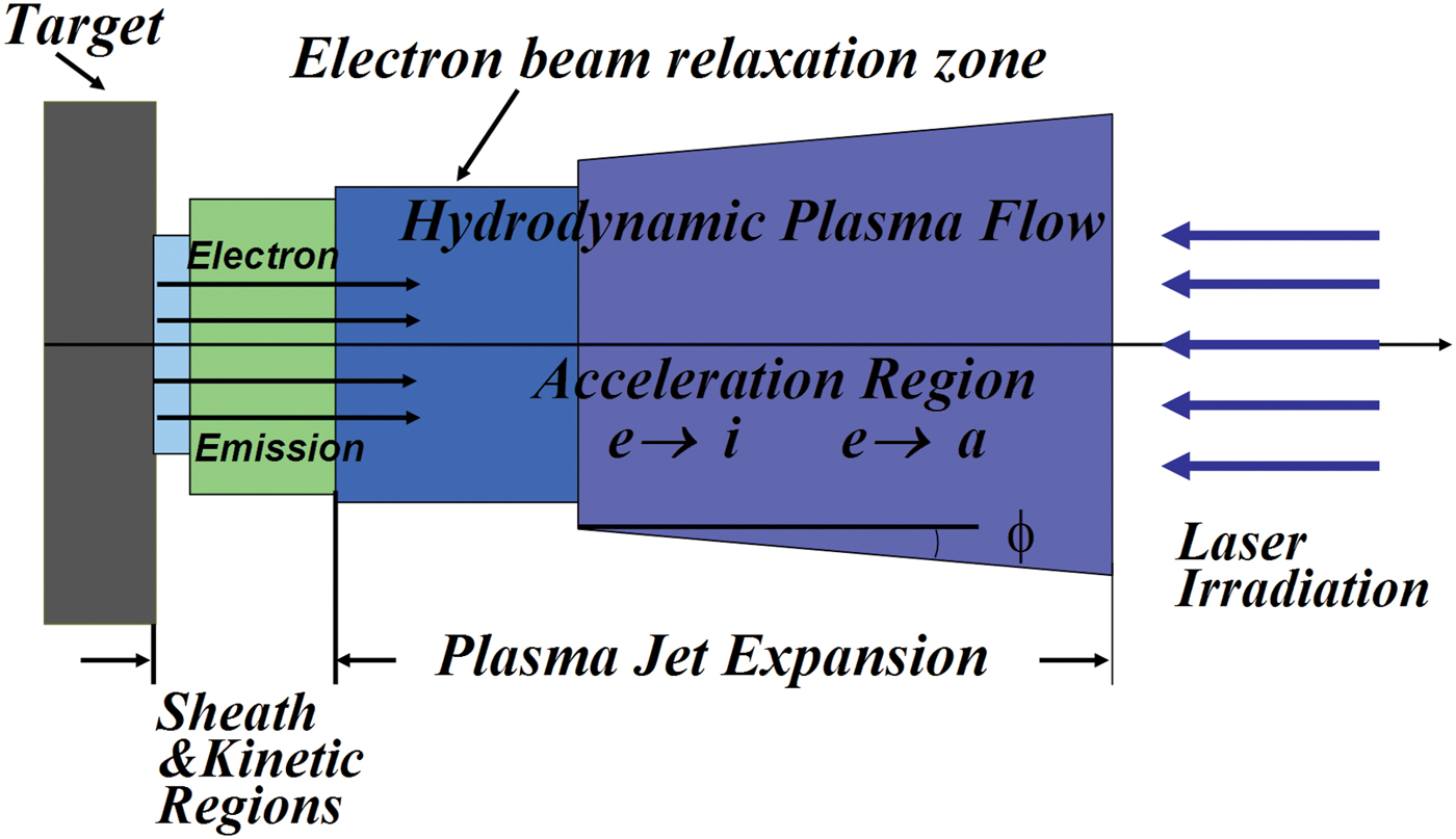
Fig. 1. (Color online) Schematic presentation of the characteristic regions of laser plasma expansion.
The electron emission with current density j em and mass flux G (g/s) emitted from the target is taken in account assuming plasma expansion in the geometrical form of a truncated cone (Fig. 1) with cross-section F depending on distance from the target x (Beilis, Reference Beilis2003). The plasma parameters can be described by a set of hydrodynamic equations of mass, momentum and energy conservation in the expanding plasma flow in 2D approximation developed by Keidar and Beilis (Reference Keidar, Beilis, Boxman and Goldsmith1996). This approach assumes a nearly uniform radial plasma distribution in the expanding jet (Keidar et al., Reference Keidar, Beilis, Boxman and Goldsmith1996) and therefore the following quasi-one-dimensional system of first-order equations may be presented as:
(1) Continuity, Momentum and Energy of Ionized Vapor Flow:


(2) Electron Energy:


The main mechanism of energy absorption in the plasma and therefore electron heating is inverse Bremsstrahlung. The inverse bremsstrahlung coefficient α IB(x) is determined by the laser wave length λ, and depends on distance x from the target and can be calculated as (Singh & Narayan, Reference Singh and Narayan1990):

(3) Ion Continuity:
(4) Electron continuity:

(5) Electric Field:
where q L is the laser power density, n h is the heavy particle density, τef is the effective time between electron-ion and electron-atom collisions, n e and n i are ion and electron densities, respectively, n es is the equilibrium plasma density at the sheath edge, βi and βr are the coefficients of ionization and recombination, h is the Plank constant, T e is the electron temperature in eV, T(°K) is the heavy particle temperature, σi and σc are the cross-sections of atom ionization and Coulomb collisions, respectively, ɛo is the vacuum permittivity, U i is the atomic ionization energy, E p is the electric field in the plasma, and L ef is an effective dense plasma length.
Eqs. (8) and (9) take in account that the atoms are ionized by the emitted electron beam with current density j em and by the plasma electrons with T e. Usually the plasma is quasineutral (n e≈n i = n), and E p is determined by the gradient of the electron pressure (see below Eq. (12)). A deviation from quasi-neutrality is possible in the flow far from the surface at the front of the expanding plasma where a large electric field E p can be induced (see Section 5). In this case, E p can be estimated from Eq. (5) and Eq. (10). The above system of equations can be solved using the boundary conditions described in Section 3.1 and developed for laser generated plasma near the target surface (Beilis, Reference Beilis2007).
5. PLASMA ACCELERATION MECHANISM
Let us consider the possible mechanisms for accelerating fully ionized plasma having conductivity σ. The equation of ion motion in general form is:
where P i is the ion pressure, V i is the ion velocity, j is the electrical current density, and ![]() is the magnetic field vector. The electric field E is limited by high electron mobility in a quasi-neutral plasma. In order to study the electrical field generation mechanisms while maintaining quasi-neutrality, the equation of electron motion with velocity V e and pressure P e may be considered in the following form:
is the magnetic field vector. The electric field E is limited by high electron mobility in a quasi-neutral plasma. In order to study the electrical field generation mechanisms while maintaining quasi-neutrality, the equation of electron motion with velocity V e and pressure P e may be considered in the following form:
![e\left(E - \displaystyle{{\vec j} \over {\rm \sigma} }\right)=- \displaystyle{{\nabla P_e } \over {n_e }} - \displaystyle{{md\vec V_e } \over {dt}} - \displaystyle{e \over c}\left[{\vec V_e \vec H} \right]. \eqno\lpar 12\rpar](https://static.cambridge.org/binary/version/id/urn:cambridge.org:id:binary:20151021100151072-0360:S0263034612000183_eqn12.gif?pub-status=live)
The sum of Eqs. (11) and (12) in simple case where H = 0 and j = 0 for moderate laser power is:
Considering Eq. (13), the following forces accelerating the plasma can be noted: (1) Forces due to gradient of charged particle density and by particle heating in the flow when the inertial term of electrons can be neglected. This is the gas dynamic or heat mechanism (see Section 4). (2) Electron inertia—from the last term in eq (13):
This mechanism contributes with strong V e variation in a small time. For example, when an electron velocity increases to 5 × 107 cm/s in 0.1 ns the electrical field of about 280 V/cm can be induced. (3) Force in the rarefied part of the expanding plasma caused by an electric field at the plasma front due to significantly fast motion of the hot electrons in comparison with the ions, and resulting in a strong violation of quasi-neutrality (see also Eq. (5)). The ions stream into vacuum with electrons, preceded by a characteristic length at which a space charge can be induced. This space charge at the boundary of the expanding plasma produces the accelerating electrostatic field at the ion front. The most energetic electrons extend into vacuum, maintaining an accelerating field determined by the electron temperature.
Eliezer and Ludmirsky (Reference Eliezer and Ludmirsky1983) estimated electric fields between about 5 × 10⁵ to 5 × 10⁶ V/cm at widths from 10 to 100 Debye lengths for a sheath produced by Nd:YAG laser intensities between 1012 to 1015 W/cm2. The ion acceleration with the electrostatic field E caused by the hot electrons in the freely expanding plasma model was considered by Denavit (Reference Denavit1979). This approach was extended by Wilks et al. (Reference Wilks, Langdon, Cowan, Roth, Singh, Hatchett, Key, Pennington, MacKinnon and Snavely2001) in frame of target normal sheath acceleration (TNSA) model. The expanding ions were described by the ion continuity and motion equations taking into account the electron-ion interaction. The electrons were assumed to be in isothermal equilibrium and given by the Boltzmann relation taking into account the quasi-neutrality of the plasma plume. A self-similar solution gives E = T e/L; L = V st, where V s is the ion sound speed and t is the characteristic acceleration time. Pearlman and Morse (Reference Pearlman and Morse1978) take in account effect of the truncation of the electron Maxwellian distribution and they showed that the maximal ion velocity reached when the Debye length equals the density scale length L. Thus, in essence acceleration of the ions due to the electron temperature gradient was considered. The problem of ion acceleration in a time-dependent ambipolar field was developed for the case when the electron energy strongly depends on time during a powerful sub-picosecond laser pulse (Gamaly, Reference Gamaly1993). A significant difference with the well-known case of isothermal expansion was observed (Wickens et al., Reference Wickens, Allen and Rumsby1978).
The shifted Maxwellian ion energy distribution measured for relatively moderate laser power density (≤1010 W/cm2) was proposed to explain by ion acceleration in an electric field estimated as the measured equivalent voltage ratio to the Debye length (Torrisi & Gammino, Reference Torrisi and Gammino2006). It was indicated that this electric field is in accordance with that obtained in (1–5) × 1019 W/cm2, fs and ps pulse experiments (Devies et al., Reference Devies, Bell and Tatarakis1999; Pukhov, Reference Pukhov2001; Hegelich et al., Reference Hegelich, Karsch, Pretzler, Habs, Witte, Guenther, Allen, Blazevic, Fuchs, Gauthier, Geissel, Audebert, Cowan and Roth2002). The electrostatic field model for ion acceleration was developed by Hatchett et al. (Reference Hatchett, Brown and Cowan2000) with scale length L given by the Debye length. Using one- and two-dimensional numerical simulations, Wilks et al. (Reference Wilks, Langdon, Cowan, Roth, Singh, Hatchett, Key, Pennington, MacKinnon and Snavely2001) indicated that the electrostatic acceleration mechanism (also called TNSA), is applicable only for ultra-intense (1017–1020 W/cm2), short-pulse (fs and ps) lasers when T e~MeV and L~10 µm.
Liseikina et al. (Reference Liseikina, Prellino, Cornolti and Macchi2008) indicated that in contrast to the TNSA mechanism used to explain most of the experiments with ion acceleration from solid targets, laser radiation pressure acceleration (RPA), predicted from theoretical studies, becomes dominant at intensities exceeding 1023 W/cm2 and produces highly collimated ions with energies approaching GeV values. Previously, Attwood et al. (1978) presented interferometric data that confirmed the significant role of radiation pressure during laser-plasma interaction (1023 W/cm2). Thus, the electrostatic acceleration mechanism or TNSA and RPA models are mainly applicable for extremely high intensity LTI.
6. CALCULATION OF THE PLASMA PARAMETERS FROM LASER: AG TARGET INTERACTION
The plasma parameters determine how the laser beam interacts with metallic plasma. The plasma parameters depend on the plasma generation and expansion mechanisms. It was shown that the plasma is mostly generated near the target surface. Plasma interaction with a solid surface is complicated. It includes target heating and ablation, generation of high vapor pressure, electron emission from the hot target, and plasma heating and electrical sheath formation at the target-plasma interface (Section 2). Below a self-consistent calculation example that analyzes the physics of laser ablation is presented, taking into account the mentioned above physical phenomena and based on model developed by Beilis (Reference Beilis2006, Reference Beilis2007, Reference Beilis2008).
According to the model, the near target plasma flow consists of several physical regions (Fig. 1) including the electrical sheath, a non-equilibrium Knudsen layer, and then a plasma region where the emitted electrons relax. The gas-dynamic Eqs. (4)–(10) were taken in integral form to calculate the velocity V of the accelerated plasma jet. The system of equations (Beilis, Reference Beilis2007) includes the heat-conduction equation for target heating, an equation for the potential drop in the sheath, equations for atom evaporation and electron emission from the target, and target and plasma energy balances. It was taken in account that the laser power density q L is dissipated not only in the target body but also in the electron relaxation region and in the expanding plasma jet. The plasma parameters were calculated for the conditions in the experiment by Margarone et al. (Reference Margarone, Torrisi, Borrielli and Caridi2008) in which a 10 ns, power density q L = 10–100 MW/cm2 laser beam was incident on a 3 mm2 spot of an Ag target. The dependencies on q L was calculated, when for simplicity, the coefficient of power absorption in the plasma jet was taken as a constant α IB = 0.4. And, to determine the influence of α IB on the plasma parameters, it was varied while q L was held constant (Beilis, Reference Beilis2007; Bogaerts et al., Reference Bogaerts, Chen, Gijbels and Vertes2003). The coefficient of power absorption in the electron relaxation region was taken as K e = 0.1 (Beilis, Reference Beilis2007). The important characteristic is the evaporation fraction K er that is the calculated net of target evaporation rate ratio to that rate determined by Langmuir flux into vacuum W L(Section 3.1).
It was found that the potential drop in the sheath and the electron temperature T e decrease with increasing q L (Fig. 2). The target temperature T 0 increases and therefore the target evaporation fraction also increases with q L (Fig. 3) indicating the vapor non-equilibrium degree at the target. As T 0 increases the heavy particle density n h also increases, so that the degree of ionization α decreases with increasing q L (Fig. 4). The emitted electron current density j e increases by six orders of magnitude while ion current density j i increases by one order of magnitude with increasing q L (Fig. 5). The returned electron current density j et exceeds j em (Fig. 5) so that the total current will be zero for all considered q L. The electrical field at the target surface increase with q L to a maximum of 4 MV/cm at q L = 15 MW/cm2, and then decreased with further increases of q L, while the target ablation rate G increases by six orders of magnitude with q L (Fig. 6). G increases because the target temperature increases with q L. The laser plasma is significantly accelerated by the gas-dynamic mechanism, above 106 cm/s and V as well the kinetic jet energy (mV 2/2) increase with α IB for constant q L (Fig. 7). However, when α IB. is constant the velocity V decreases with q L.

Fig. 2. (Color online) Potential drop in the space charge region near the target surface and plasma electron temperature as a function on laser power density, 10ns pulse.

Fig. 3. (Color online) Surface target temperature T 0 and target evaporation fraction K er dependencies on laser power density, 10 ns pulse.

Fig. 4. (Color online) Dependencies of heavy particle density n h and degree of ionization α in the beam relaxation region as function of laser power density, 10 ns pulse.

Fig. 5. (Color online) Electron emission j e, ion j i and returned electron j et current densities as a function on laser power density, 10 ns pulse.

Fig. 6. (Color online) Electric field at the target surface in the sheath and target ablation rate vs. laser power density, 10 ns pulse.

Fig. 7. (Color online) Jet velocity V, jet energy W and heavy particle density n h as function of coefficient of energy absorption αL in the plasma jet calculated for Ag target with laser pulse 9 ns, qL= 33.333 × MW/cm2.
These different dependencies can be understood from relation between α IB, q L, and n h in form:
The relation (15) is obtained combining the equations of jet momentum (4) and energy conservation (5) in integral form, taking into account that the absorbed power density α IBq L causes the plasma heating and its acceleration. The self-consistent calculation shows that the character of heavy particle density dependence on α IB and q L variation determines the dependence of V. When α IB is constant n h increase with q L is significantly larger than the increase of q L (Fig. 3) and therefore V decreases with q L, as it follows from Eq. (15), while n h significantly decreases with α IB for constant q L and therefore V increases (also see Eq. (15)). The experiments showed that the observed peak energy of different ion species increased with laser energy (Torrisi et al., Reference Torrisi, Caridi, Margarone and Borrielli2008a, Reference Torrisi, Caridi, Margarone and Borrielli2008b, Reference Torrisi, Gammino, Ando and Laska2002; Caridi et al., Reference Caridi, Torrisi, Margarone, Picciotto, Mezzasalma and Gammino2006). This result indicate that laser energy absorption is non-linearly function on distance in the expanding plasma jet and the plasma velocity is determined by a dependence α IB (x) which, as example, was used by Bogaerts et al. (Reference Bogaerts, Chen, Gijbels and Vertes2003) for Cu and power density >108 W/cm2.
7. DISCUSSIONS
It may be seen from the LTI experiments and theory described above, that the behavior of the plasma parameters, plasma expansion, and ion acceleration is a result of complex phenomena, which appear during laser plasma formation and development in the kinetic and hydrodynamic regions. The first stage of LTI is characterized by the intense target ablation when mainly neutral atoms were observed and the breakdown of neutral vapor occurs in the second stage producing the laser plasma plume. This transient stage can be understood taking into account the breakdown mechanisms described in Section 3.2. The next stage occurs when the near-target plasma has been produced and the plasma plume expands simultaneously with target heating and ablation, and the part of laser energy dissipated in the plasma. At this stage, the important issue is to determine the plasma parameters, taking into account the mentioned mutual phenomena (Sections 3.1–3.5, 4, and 5) solving the mathematical problem self-consistently. Let us discuss the calculated results at the last stage of LTI.
In general, the present and previous calculations (Beilis, Reference Beilis2007) show that the target vaporizes in a dense near-target plasma that is separated from the solid surface by an electrical sheath with a relatively large potential drop and by a Knudsen layer across, which there is a jump of plasma parameters and a mass flux also toward the target. The electrons emitted from the hot target are accelerated in the sheath. The electron beam energy is dissipated in the electron relaxation region whose length is significantly larger than the length of the Knudsen layer. As result, the plasma flow in the vicinity of the target surface is impeded by the dense plasma and the electron beam energy dissipation. This is very important in understanding the target ablation rate. The calculated results for Al and Cu targets (Beilis, Reference Beilis2007, Reference Beilis2008) showed: (1) the dependence of target rate ablation on pulse energy density well agrees with experiments (Caridi et al., Reference Caridi, Torrisi, Margarone, Picciotto, Mezzasalma and Gammino2006); (2) the plasma significantly converts the absorbed laser energy to kinetic and potential energy of the plasma particles, which transport part of the energy through the electrostatic sheath back to the solid surface; (3) the energy flux from the adjacent plasma significantly contribute to heating the target; (4) the calculated electron temperature of 1–5 eV agrees well with other calculated results (Bogaerts et al., Reference Bogaerts, Chen, Gijbels and Vertes2003) and is the range measured by direct spectroscopic methods (see Table 1). This last result is important in understanding the electrostatic fields produced by LTI with moderate power density.
The plasma acceleration depends on the laser energy absorbed in the relaxation region, in the expanding plasma jet and on the rate of target ablation. The calculations show (see also Section 6) that the observed plasma jet velocity can be explained by the gas-dynamic mechanism of plasma acceleration (Beilis, Reference Beilis2007). The distribution of α IB(x) should be taken into account for correctly and quantitatively describe the measured jet velocity increase with laser power density. Inside of the gas-dynamic region (Fig. 1), the dense plasma is quasi-neutral and therefore the electric field is relatively small.
The important issue is to understand the mechanism producing the observed ion energy distribution and the shifted equivalent voltage per charge state. One of the approaches of the previously published works (TNSA, see Section 5) takes into account that the plasma quasi-neutrality is violated and a space charge region with a potential drop U f (whose value depends on T e) can appear. Although this mechanism was widely used, the sheath structure was not considered especially, for moderate laser power density when the electron temperature is relatively small, the ion acceleration in the expanding electrical sheath is not detailed. In most cases the characteristic length of the space charge region was chosen to be the Debye length. The electric field E was calculated using the measured shifted equivalent voltage as U f and Debye length L D i.e., E = U f/L D. In this case, the acceleration mechanism remains unknown because namely U f should be determined. Although the particle acceleration depends on electrical field the particle energy is determined by potential drop in the acceleration region. Note also that Debye length is a parameter characterizes the scale of E where the quasi-neutrality violated and the potential of charged particle interaction about T e/e. The effect of quasi-neutrality violation takes place also at the expanding plasma front, but the characteristic length depends on the whether the plasma is expanding into vacuum, into a gas or impinges onto a solid wall. In this case, the particle energy acquired by electrostatic acceleration in the space charge region cannot exceed the electron temperature although there is a relatively large electric field in a small region (whose size is the Debye or other length). Therefore the ion acceleration by the electrostatic mechanism described well the experiment with ultra-intense (>1015 W/cm2) laser irradiation when T e is about MeV. In contrast, for intermediate laser power density, the electrostatic TNSA mechanism cannot explain the observed relatively large ion energy shift per charge because the spectroscopic direct measurements showed that the expanding plasma has relatively low T e.
The ion acceleration can be described taking into account that there a strong gradient of plasma pressure in the expanding plasma (Zeldovich & Raizer, Reference Zeldovich and Raizer1966). The effect of the pressure gradient can be considered by integrating Eq. (13) across some characteristic length in the plasma between distances x 1 and x 2 from the target and taking into account the equation of plasma state. In this case the ion energy increase ΔW z0 = W z0(x 2) -W z0(x 1) with Z i0 charge can be obtained in form:
![$$\eqalign{\Delta W_{z0}&=Z_0 \left[\left(\displaystyle{{T_i } \over {Z_0}}+T_e \right)Ln\left(\displaystyle{{n_{z0} (x_1)} \over {n_{z0} (x_2)}}\right)\right. \cr & \left. +\vint \sum\limits_{z \ne z0} \displaystyle{{n_{iz} } \over {Z_0 n_{z0} }} \left(\displaystyle{{dT_i } \over {dx}} +Z\displaystyle{{dT_e } \over {dx}}\right)dx\right. \cr & \left. +\vint \sum\limits_{z \ne z0} \displaystyle{{(T_i+ZT_e)} \over {Z_0 n_{z0} }} \displaystyle{{dn_{iz} } \over {dx}}dx \right].}\eqno\lpar 16\rpar](https://static.cambridge.org/binary/version/id/urn:cambridge.org:id:binary:20151021100151072-0360:S0263034612000183_eqn16.gif?pub-status=live)
And in simple form this dependence is:
where W z0 = mV z02/2 is the ion kinetic energy, Z and Z0 is the charge of ions with density n iz and n iz0, respectively, F(T e,n iz,Z) is a function expressing the sum of second and third terms on the right side of Eq. (16) and which describes the influence of the pressure gradient for ion charges Z ≠ Z 0. Eqs. (16) and (17) show that the ion energy linearly depends on the ion charge state, as observed experimentally (Section 2). The ion energy also depends on a jump of plasma parameters produced after the vapor breakdown by laser irradiation. A strong jump of Te and n e can appear over a region of few mean free paths at the plasma front (Zeldovich & Raizer, Reference Zeldovich and Raizer1966; Raizer, Reference Raizer Yu1974). The simultaneous existence of “hot” electrons and “cold” electrons which induce rarefaction shock waves with discontinuities in the plasma potential was indicated by Eliezer and Hora (Reference Eliezer and Hora1988). The jump characteristic should be studied taking into account the plasma front interaction with the incident laser pulse.
Another result that should be understood is the relatively wide dispersion observed in the ion energy distribution that increases for ions with larger charge. This dispersion was interpreted as a very large ion temperature, up to about 105 K. However, the measurements and calculations show that T e is low in the dense plasma region, as mentioned above (see Table 1). The plasma is non-equilibrium, i.e., T e ≠ T, and the efficiency of energy transfer from the electrons to the heavy particle is too weak to reach equilibrium. One possible interpretation considers that the effect of the wide ion energy distribution is similar to that measured in plasma jets of a vacuum arc (Davis & Miller, Reference Davis and Miller1969). The ion energy distribution in the vacuum arc was explained by superposition of the jets generated by multiple cathode spots (Beilis et al., Reference Beilis and Keidar1998). It can be taken into account also that the ion energy substantially increases when the erosion rate decreases in arcs with large rate of current or power rise during the discharge pulse (Beilis, Reference Beilis2004).
Thus, similarly to the vacuum arc phenomena, the laser ion energy dispersion can be explained taking into account the different plasma jet parameters generated, for example, in experiments with multi-pulse laser irradiation of the target. In this case the plasma parameters produced by a laser pulse depends on the target surface features produced by the previous pulse. Indeed, roughening of Si surfaces treated by nanosecond laser pulses was shown by Schwarz-Selinger et al. (Reference Schwarz-Selinger, Cahill, Chen, Moon and Grigoropoulos2001). Consequently, the plasma parameters are determined by the vaporization rate of surface irregularities and a target erosion rate will not be uniform. Surface non-uniformity causes the observed ion energy variation because the ion acceleration depends on the target local erosion rate, which depends on the local target surface morphology. The morphology varies during a single pulse and from pulse to pulse. The origin of ion energy variation can be explained taking into account the large incoming laser power intensity in short laser pulses and the mechanism of ion acceleration depending on target ablation rate by analogy to the cathode erosion rate in arcs (Beilis, Reference Beilis2004). It should be noted that plasma structure formation due to non-uniformity of power density distribution within the laser spot in single laser pulse also was indicated by Hora (Reference Hora1981).
ACKNOWLEDGMENT
The author would like to thank to Prof. R.L. Boxman for useful discussion improving the paper presentation.


