


INTRODUCTION
The irradiation of different materials by subpicosecond laser pulses with relativistic intensities I ≳ 1019 W/cm2 is widely used (Ditmire et al., Reference Ditmire, Bless, Dyer, Edens, Grigsby, Hays, Madison, Maltsev, Colvin, Edwards, Lee, Patel, Price, Remington, Sheppherd, Wootton, Zweiback, Liang and Kielty2004), especially for the development of X-ray sources, warm dense matter investigation (Zastrau et al., Reference Zastrau, Audebert, Bernshtam, Brambrink, Kämpfer, Kroupp, Loetzsch, Maron, Ralchenko, Reinholz, Röpke, Sengebusch, Stambulchik, Uschmann, Weingarten and Förster2010), fast ignition (Kitagawa et al., Reference Kitagawa, Fujita, Kodama, Yoshida, Matsuo, Jitsuno, Kawasaki, Kitamura, Kanabe, Sakabe, Shigemori, Miyanaga and Izawa2004), radiative shocks (Stehlé et al., Reference Stehlé, González, Kozlova, Rus, Mocek, Acef, Colombier, Lanz, Champion, Jakubczak, Polan, Barroso, Bauduin, Audit, Dostal and Stupka2010), and particle acceleration (Carroll et al., Reference Carroll, Tresca, Prasad, Romagnani, Foster, Gallegos, Ter-Avetisyan, Green, Streeter, Dover, Palmer, Brenner, Cameron, Quinn, Schreiber, Robinson, Baeva, Quinn, Yuan, Najmudin, Zepf, Neely, Borghesi and McKenna2010). For these experiments, the laser contrast is a key parameter that can be defined as the ratio of the prepulse intensity to the peak one. Depending on the pulse amplification technique, the duration and intensity of the prepulse can vary, and the contrast ratio in the case of chirped amplification at ~1 ns before the main short pulse is about 10−6 as reported (Bagnoud et al., Reference Bagnoud, Aurand, Blazevic, Borneis, Bruske, Ecker, Eisenbarth, Fils, Frank, Gaul, Goette, Haefner, Hahn, Harres, Heuck, Hochhaus, Hoffmann, Javorkova, Kluge, Kuehl, Kunzer, Kreutz, Merz-Mantwill, Neumayer, Onkels, Reemts, Rosmej, Roth, Stoehlker, Tauschwitz, Zielbauer, Zimmer and Witte2010). Undesirable effects of the long prepulse can be reduced at least several orders of magnitude using the plasma mirror technique (Carroll et al., Reference Carroll, Tresca, Prasad, Romagnani, Foster, Gallegos, Ter-Avetisyan, Green, Streeter, Dover, Palmer, Brenner, Cameron, Quinn, Schreiber, Robinson, Baeva, Quinn, Yuan, Najmudin, Zepf, Neely, Borghesi and McKenna2010; Doumy et al., Reference Doumy, Quéré, Gobert, Perdrix, Martin, Audebert, Gauthier, Geindre and Wittmann2004) or frequency doubling (Zastrau et al., Reference Zastrau, Audebert, Bernshtam, Brambrink, Kämpfer, Kroupp, Loetzsch, Maron, Ralchenko, Reinholz, Röpke, Sengebusch, Stambulchik, Uschmann, Weingarten and Förster2010). Actual laser setups with good enough characteristics produce a contrast of the order of 10−8 that gives the intensity level I ~ 1012 W/cm2 for the nanosecond prepulse. Such prepulse intensity is sufficient to produce plasma at the surface of a solid target, change the dynamics of high-intensity laser-matter interaction (McKenna et al., Reference McKenna, Lindau, Lundh, Neely, Persson and Wahlström2006), and destroy the surface-structured targets (Ovchinnikov et al., Reference Ovchinnikov, Kostenko, Chefonov, Rosmej, Andreev, Agranat, Duan, Liu and Fortov2011).
In our recent paper (Povarnisyn et al., 2012a), we discussed the possible way of the contrast improvement by placing a thin metal film ahead of the main target and thereby cutting off the long nanosecond prepulse. The multi-stage thin film dynamics has been investigated from the initial stage of the film heating, material rarefaction until the moment of almost full ionization and electron density dropping below the critical value when the plasma becomes transparent for the laser beam. Another important process that determines the channel of laser energy transformation is the re-emission effect that governs both the radiation heating of the film and emissivity of the film plasma. The later case, as was shown earlier (Povarnistyn et al., 2012a), is important for proper estimation of the main target preheating.
In this paper, we analyze numerically the dynamics of thin films irradiated by a nanosecond prepulse using the wide-range model of radiation hydrodynamics (Povarnitsyn et al., Reference Povarnitsyn, Andreev, Levashov, Khishchenko and Rosmej2012a). The paper is organized as follow. The first section introduces baseline designs. In the second section, we describe the basic features of the model. Then, the third section is devoted to results of modeling for Al and CH2 films and Ag target.
MODEL
Equations of Radiation Hydrodynamics
The basic features of the model used for simulation of the laser-matter interaction are described (Povarnitsyn et al., Reference Povarnitsyn, Andreev, Levashov, Khishchenko and Rosmej2012a). The model takes account of 1D hydrodynamic motion of substance, laser energy absorption, two-temperature nonequilibrium states for electron and ion subsystems, electron thermal conductivity and radiation transport in diffusion approximation. The evolution of material parameters is described using the conservation of mass, momentum and energy of electron and ion subsystems in a single-fluid two-temperature Lagrangian form:
 $$\displaystyle{{\partial \lpar 1/{\rm \rho} \rpar } \over {\partial t}} - \displaystyle{{\partial u} \over {\partial m}}=0\comma \;$$
 $$\displaystyle{{\partial u} \over {\partial t}}+\displaystyle{{\partial \lpar P_i+P_e \rpar } \over {\partial m}}=0\comma \;$$
 $$\eqalign{\displaystyle{{\partial e_e } \over {\partial t}}+P_e \displaystyle{{\partial u} \over {\partial m}} & = - {\rm \gamma} _{ei} \lpar T_e - T_i \rpar /{\rm \rho} +Q_L /{\rm \rho}+\displaystyle{\partial \over {\partial m}}\left({{\rm \rho} {\rm \kappa} _e \displaystyle{{\partial T_e } \over {\partial m}}} \right)- \displaystyle{{\partial S} \over {\partial m}}\comma \; }$$
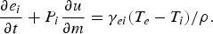 $$\displaystyle{{\partial e_i } \over {\partial t}}+P_i \displaystyle{{\partial u} \over {\partial m}}={\rm \gamma} _{ei} \lpar T_e - T_i \rpar /{\rm \rho}.$$
Here ρ is the density; t is the time; m is the mass coordinate, dm = ρdz with the space coordinate z; u is the velocity; P, e, T are the pressure, specific energy and temperature, respectively. Indices e and i stand for electron and ion species. The energy exchange between electrons and ions is described by the corresponding term with the coupling factor γei(ρ, T e, T i). The electron heat transfer is specified with the aid of the thermal conduction coefficient κe(ρ, T e, T i). Optical and transport properties of Al and Ag plasma are taken into account by means of wide-range models (Povarnisyn et al., 2012b; Veysman et al., Reference Veysman, Agranat, Andreev, Ashitkov, Fortov, Khishchenko, Kostenko, Levashov, Ovchinnikov and Sitnikov2008). For CH2 material, we use a similar approach interpolating between dense preionized state (Drude model) and Spitzer ideal plasma (Spitzer & Härm, Reference Spitzer and Härm1953). The key parameter in these models is the frequency of collisions (electron–phonon, electron–ion, and electron–electron). In the metal state, it can be written as follows
 $${\rm \nu} _{\rm met}=A_1\, k_B T_i /\hbar+A_2\, k_B T_e^2 /\lpar T_F \hbar \rpar.$$
Here k B and ħ are the Boltzmann and Planck constants, respectively, and T F is the Fermi temperature. The frequency is limited from above by the electron free-path between ions so that
 $${\rm \nu} _{\rm max}=\displaystyle{{A_3 } \over {r_0 }}\sqrt {{\rm \upsilon} _F^2+k_B T_e /m_e }\comma \;$$
where υ F is the Fermi speed of electrons, r 0 is the interatomic distance and m e is the electron mass.
For hot states T e ≫ T F with not very high densities, the plasma model (Spitzer & Härm, Reference Spitzer and Härm1953) is relevant
 $${\rm \nu} _{\rm pl}=\displaystyle{4 \over 3}\sqrt {2{\rm \pi} } \displaystyle{{\left\langle Z \right\rangle n_e e^4 \Lambda } \over {\sqrt {m_e } \lpar k_B T_e \rpar ^{3/2} }}\comma \;$$
where 〈Z〉 is the mean charge of ions, n e is the electron concentration, e is the electron charge, and Λ is the Coulomb logarithm.
The electron thermal conductivity in the metal is calculated according to the Drude formalism as follows
 $${\rm \kappa} _{\rm met}=\displaystyle{{{\rm \pi} ^2\, k_B^2 n_e } \over {3m_e {\rm \nu} _{\rm eff} }}T_e\comma \;$$
where ν eff = min(ν met, ν max). The hot plasma limit is
 $${\rm \kappa} _{\rm pl}=\displaystyle{{16\sqrt 2\, k_B \lpar k_B T_e \rpar ^{5/2} } \over {{\rm \pi} ^{3/2} \left\langle Z \right\rangle e^4 \sqrt {m_e } \Lambda }}.$$
An interpolation between (8) and (9) in the vicinity of the Fermi temperature gives us a wide-range expression for the thermal diffusivity,
 $${\rm \kappa}={\rm \kappa} _{\rm pl}+\lpar {\rm \kappa} _{\rm met} - {\rm \kappa} _{\rm pl} \rpar \exp\left[{ - A_4 T_e /T_F } \right].$$
The dimensionless parameters A 1, A 2, A 3, A 4 are used to adjust the model to available theoretical and experimental data. For the thermal conduction of Ag, the parameters are A 1t = 0.7, A t2 = 0.5, A t3 = 1.0, A t4 = 3.0. In Figure 1, we compare the results of the interpolation (10) with the theoretical data (Apfelbaum, Reference Apfelbaum2011) for normal and 0.1 of normal density. Appropriate coefficients of the model for Al are A t1 = 2.95, A t2 = 0.5, A t3 = 0.16, A t4 = 1.2, see Figure 2 in paper byPovarnitsyn et al. (Reference Povarnitsyn, Andreev, Apfelbaum, Itina, Khishchenko, Kostenko, Levashov and Veysman2012b).

Fig. 1. (Color online) The thermal conductivity coefficient of Ag. Comparison of interpolation formula (10) (lines) with available theoretical data (Apfelbaum, Reference Apfelbaum2011) (signs) in cases of normal and 0.1 of normal densities, T i = T e.
Fig. 2. (Color online) The coupling factor of Ag according to the model (11) (lines) and theoretical results (Lin et al., Reference Lin, Zhigilei and Celli2008) (signs) for normal density.
The coupling factor is written in the form
 $${\rm \gamma} _{ei}=\displaystyle{{3k_B m_e } \over {m_i }}n_e {\rm \nu} _{\rm eff}\comma \;$$
where m i is the ion mass, and ν eff = min(νmet, ν max, ν pl) is given by expressions (5), (6), (7). For Ag, the dimensionless parameters are A g1 = 10.0, A g2 = 10.0, A g3 = 0.4. The coupling factor (11) and results of first-principle calculations (Lin et al., Reference Lin, Zhigilei and Celli2008) are presented in Figure 2 for Ag. Appropriate coefficients for Al can be found in paper by Povarnitsyn et al. (Reference Povarnitsyn, Andreev, Apfelbaum, Itina, Khishchenko, Kostenko, Levashov and Veysman2012b).
The laser energy absorption (bremsstrahlung process) is taken into account with the aid of heat source term Q L (t, z). To find it we solve the Helmholtz wave equation for the laser electric field with proper boundary conditions (Povarnitsyn et al., Reference Povarnitsyn, Andreev, Levashov, Khishchenko and Rosmej2012a)
 $$\displaystyle{{\partial ^2 E} \over {\partial z^2 }}+\displaystyle{{{\rm \omega} _L^2 } \over {c^2 }}{\rm \epsilon} \lpar z\rpar E=0.$$
Here the normal incidence is supposed, E is the laser electric field envelope, ωL is the laser frequency, c is the speed of light, ε(ρ, T e, T i) is the complex dielectric function. The resulting laser heating source is
 $$Q_L \lpar t\comma \; z\rpar =I\lpar t\rpar \displaystyle{{{\rm \omega} _L } \over c} {\rm Im}\lcub {\rm \epsilon} \lpar t\comma \; z\rpar \rcub \vert E\lpar t\comma \; z\rpar /E_L \lpar t\rpar \vert ^2\comma \;$$
where the incident laser field amplitude is 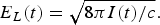 $E_L \lpar t\rpar =\sqrt {8{\rm \pi} I\lpar t\rpar /c} .$
The radiation transport is taken into account by the integral over the spectrum flux 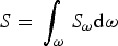 $S=\,\vint_{\rm \omega} \, S_{\rm \omega} {\rm d}{\rm \omega} $. The equations of radiation transport are written in diffusion approximation:
 $$\displaystyle{{\partial S_{\rm \omega} } \over {\partial z}}=4{\rm \pi} j_{\rm \omega} - {\rm \kappa} _{\rm \omega} cU_{\rm \omega}\comma \;$$
 $$S_{\rm \omega}=- \displaystyle{c \over {3{\rm \kappa} _{\rm \omega} }}\displaystyle{{\partial U_{\rm \omega} } \over {\partial z}}\comma \;$$
 $$\mathop {\left. {S_{\rm \omega} } \right\vert }\nolimits_\Omega=\mp \displaystyle{{cU_{\rm \omega} } \over 2}\comma \;$$
where S ω is the radiation flux density, U ω is the radiant energy density, j ω and κ ω are the coefficients of emissivity and absorption, respectively, and Ω is the external boundary of plasma.
Equations of state (EOSs) for Al, CH2, and Ag determine the relations P e(ρ, T e ), P i(ρ, T i ), e e(ρ, T e ), e i(ρ, T i) and are necessary for completeness of system (1)–(4). These EOSs are based on the analytical expression of the Helmholtz free energy that has a form ℱ(ρ, T i, T e) = ℱi(ρ, T i) + ℱe(ρ, T e), and is composed of two parts. The first item stands for the ionic part ℱi(ρ, T i) = ℱc(ρ) + ℱa(ρ, T i), and consists of the electron-ion interaction term ℱc (calculated at T i = T e = 0 K) and the contribution of the thermal motion of ions ℱa. The analytical form of ℱi has different expressions for solid and fluid phases (Khishchenko, Reference Khishchenko2008). The tables of thermodynamic parameters are calculated to take into account phase transitions and metastable regions (Khishchenko et al., Reference Khishchenko, Tkachenko, Levashov, Lomonosov and Vorob'ev2002; Levashov & Khishchenko, Reference Levashov and Khishchenko2007; Oreshkin et al., Reference Oreshkin, Baksht, Ratakhin, Shishlov, Khishchenko, Levashov and Beilis2004). The second term ℱe(ρ, T e) describes the thermal contribution of electrons calculated with the aid of the Thomas–Fermi model (Shemyakin et al., Reference Shemyakin, Levashov, Obruchkova and Khishchenko2010).
Absorption and Emission Coefficients
As was demonstrated in Povarnitsyn et al. (Reference Povarnitsyn, Andreev, Levashov, Khishchenko and Rosmej2012a) the radiation transport is a key effect in the dynamics of thin films illuminated by nanosecond prepulses with intensity ≳1011 W/cm2. Transformation of monochromatic laser energy into a wide spectrum of photons results in formation of noticeable re-emission fluxes on both sides of the film. We focus here on the detailed description of the procedure for calculation of absorption and emission coefficients. These coefficients depend on ion concentrations. To obtain concentrations x ks of k-fold ionized atoms or molecules in the state s the system of level kinetic equations is solved in quasi-stationary approximation:
 $$\eqalign{\displaystyle{{{\rm d}x_{ks} } \over {{\rm d}t}} & =- x_{ks} \left({\sum\limits_{s^{\prime}} \, R_{ks \to k - 1\comma s^{\prime}}+\sum\limits_{s^{\prime}} \, I_{ks \to k+1\comma s^{\prime}} } \right. +\left. {\sum\limits_{s^{\prime}} \, {\rm \alpha} _{ks \to ks^{\prime}} } \right)\cr & \quad +\sum\limits_{s^{\prime}} \, x_{k+1\comma s^{\prime}} R_{k+1\comma s^{\prime} \to k\comma s} +\sum\limits_{s^{\prime}} \, x_{k - 1\comma s^{\prime}} I_{k - 1\comma s^{\prime} \to k\comma s}\cr & \quad+\sum\limits_{s^{\prime}} \, x_{ks^{\prime}} {\rm \alpha} _{ks^{\prime} \to ks}=0.}$$
In Eq. (15) the rate of recombination from the ion state ks to the state k − 1, s′ is given by
 $$\eqalign{R_{ks \to k - 1\comma s^{\prime}} & ={\rm \alpha} ^{ir} \lpar ks \to k - 1\comma \; s^{\prime}\rpar \cr & \quad +{\rm \alpha} ^{\,phr} \lpar ks \to k - 1\comma \; s^{\prime}\rpar \cr & \quad +{\rm \alpha} ^{dc} \lpar ks \to k - 1\comma \; s^{\prime}\rpar \comma \;}$$
where αir(ks → k − 1, s′), α phr(ks → k − 1, s′), and αdc(ks → k − 1, s′) are the rates of three-body recombination, photo-recombination and dielectronic capture, respectively. The rate of ionization from ks to k + 1, s′ state is given by
 $$\eqalign{I_{ks \to k+1\comma s^{\prime}} & ={\rm \alpha} ^{ii} \lpar ks \to k+1\comma \; s^{\prime}\rpar \cr & \quad +{\rm \alpha} ^{\,phi} \lpar ks \to k+1\comma \; s^{\prime}\rpar \cr & \quad +{\rm \alpha} ^{ai} \lpar ks \to k+1\comma \; s^{\prime}\rpar \comma \;}$$
where αii(ks → k + 1, s′), αphi(ks → k + 1, s′), and αai(ks → k + 1, s′) are the rates of impact ionization, photo-ionization and auto-ionization, respectively. The rates of transitions from ks to ks′ without a change of ionization stage are written as follows
 $${\rm \alpha} _{ks \to ks^{\prime}}=\left\{{\matrix{ {{\rm \alpha} ^{ex} \lpar ks \to ks^{\prime}\rpar +{\rm \alpha} ^{abs} \lpar ks \to ks^{\prime}\rpar \comma \; } \cr \hfill {{\rm if}\, E_{ks}\lt E_{ks^{\prime}}\comma \; } \cr {{\rm \alpha} ^{dex} \lpar ks \to ks^{\prime}\rpar +{\rm \alpha} ^{em} \lpar ks \to ks^{\prime}\rpar \comma \; } \cr \hfill {{\rm if}\, E_{ks}\gt E_{ks^{\prime}}\comma \; }}} \right.$$
where E ks is the energy of ion state ks, αex(ks → ks′) and αdex(ks → ks′) are the rates of excitation and de-excitation by electron impact, and αabs(ks → ks′), αem(ks → ks′) are the rates of radiative excitation (absorption) and radiative emission, respectively. For calculation of these rates the Regemorter, Lotz and Kramers approximations are used (Nikiforov et al., Reference Nikiforov, Novikov and Uvarov2005; Sobel'man et al., Reference Sobel'man, Vainshtein and Youkov1995).
The number of ion states that must be taken into account can be very large. To reduce the system of kinetic equations we apply a radiative unresolved spectra atomic model (RUSAM) (Kim et al., Reference Kim, Novikov, Dolgoleva, Koshelev and Solomyannaya2012; Novikov et al., Reference Novikov, Koshelev, Solomyannaya and Fortov2010). Knowing the concentrations x ks the tables of spectral absorption coefficients and emissivities are obtained with the code THERMOS (Nikiforov et al., Reference Nikiforov, Novikov and Uvarov2005).
The concentrations x ks are defined by the radiation field U ω through the rates of the radiation processes. The photo-ionization of an electron with quantum numbers nℓ (n is the principal quantum number, ℓ is the orbital quantum number) in Kramers approximation for Q ks-configuration with occupation numbers N ksnℓ has the form:
 $${\rm \alpha} _{n\ell }^{\,phi} \lpar ks \to k+1\comma \; s^{\prime}\rpar =N_{n\ell }^{ks} u_{n\ell } \vint\limits_{{\rm \varepsilon} _{ks\semicolon k+1\comma s^{\prime}} /{\rm \theta} }^\infty \, W\lpar {\rm \xi} \rpar {\rm \xi} ^{ - 1} {\rm d}{\rm \xi}\comma \;$$
where
 $$u_{n\ell }=4.45 \times 10^{10} \, Z_k \displaystyle{{\vert {\rm \varepsilon} _{ks\semicolon k+1\comma s^{\prime}} \vert ^{3/2} } \over {2n^2 }}\comma \;$$
ɛks;k+1,s′ = E ks − E k+1,s′ is the photo-ionization threshold in atomic units, Z k is the effective charge, θ is the temperature in atomic units, W(ξ) = C ξU ω/ω3 is the radiation energy density in dimensionless units, C ξ is the dimension factor. For instance, for Planck's radiation field W(ξ) = [exp(ξ) − 1]−1. The photo-recombination rate to the level nℓ in configuration Q ks with occupation numbers N ksnℓ is given by
 $$\eqalign{{\rm \alpha} _{n\ell }^{\,phr} \lpar k+1\comma \; s^{\prime} \to ks\rpar & =C_{n\ell } u_{n\ell } N_{n\ell }^{ks} \ \times \vint\limits_{{\rm \varepsilon} _{ks\semicolon k+1\comma s^{\prime}} /{\rm \theta} }^\infty \, \displaystyle{{1+W\lpar {\rm \xi} \rpar } \over {{\rm \xi} \, {\rm exp}\lpar {\rm \xi} \rpar }}{\rm d}{\rm \xi}\comma \; }$$
where
 $$C_{n\ell }=0.704\, \displaystyle{{N_e } \over {N_A }}\displaystyle{{g_{ks} } \over {g_{k+1\comma s^{\prime}} }}\displaystyle{{\exp\lpar {\rm \varepsilon} _{ks\semicolon k+1\comma s^{\prime}} /{\rm \theta} \rpar } \over {{\rm \theta} ^{3/2} }}\comma \;$$
N A is the Avogadro constant, N e is the electron density, g ks is the statistical weight for the state ks. For given photon energy intervals [ωi, ωi+1] (i = 1, N g), absorption in lines is defined by
 $$\eqalign{{\rm \alpha} _{ks\comma ks^{\prime}}^{abs} & =3.2 \times 10^{10} \sum\limits_{i=1}^{N_g } \, \displaystyle{{\mathop {\overline {g_f } }\nolimits_i \lpar ks\comma \; ks^{\prime}\rpar } \over {g_{ks} }}\mathop {\overline {{\rm \omega} _i } ^2\lpar ks\comma \; ks^{\prime}\rpar }\nolimits \times W\left({\displaystyle{{\overline {{\rm \omega} _i } \lpar ks\comma \; ks^{\prime}\rpar } \over {\rm \theta} }} \right)\comma \; }$$
where  $\overline {{\rm \omega} _i } \lpar ks\comma \; ks^{\prime}\rpar $ is the center of line group, and
  $\mathop {\overline {g_f } }\nolimits_i \lpar ks\comma \; ks^{\prime}\rpar $ is the oscillator strength averaged over interval [ωi, ωi+1]. The line emission rate is given by
 $$\eqalign{{\rm \alpha} _{ks^{\prime}\comma ks}^{em} & =3.2 \times 10^{10} \sum\limits_{i=1}^{N_g } \, \displaystyle{{\mathop {\overline {g_f } }\nolimits_i \lpar ks\comma \; ks^{\prime}\rpar } \over {g_{ks^{\prime}} }}\mathop {\overline {{\rm \omega} _i } ^2\lpar ks\comma \; ks^{\prime}\rpar }\nolimits \cr & \quad\times \left[{1+W\left({\displaystyle{{\overline {{\rm \omega} _i } \lpar ks\comma \; ks^{\prime}\rpar } \over {\rm \theta} }} \right)} \right].}$$
Using RUSAM method the absorption coefficient in cm−1 for a photon with energy ω in the spectral interval [ωi, ωi+1] can be written in the form:
 $$\eqalign{{\rm \kappa} _i & ={\rm \rho} \displaystyle{{N_A } \over A}\left[{1 - \exp\lpar - {\rm \omega} _i^{{\rm ff}} /{\rm \theta} \rpar } \right]\left\{{\sum\limits_{ks} \, x_{ks} \sum\limits_{ks^{\prime}} \, {\rm \sigma} _i^{{\rm bb}} \lpar ks\comma \; ks^{\prime}\rpar } \right. \cr & \quad\left. {+\sum\limits_{ks} \, x_{ks} \sum\limits_{k+1\comma s^{\prime}} \, {\rm \sigma} _{ks\semicolon k+1\comma s^{\prime}}^{{\rm bf}} \lpar {\rm \omega} _i^{{\rm bf}} \rpar +{\rm \sigma} ^{{\rm ff}} \lpar {\rm \omega} _i^{{\rm ff}} \rpar } \right\}.}$$
The emissivity in TW/(cm3× eV × steradian) is written as follows:
 $$\eqalign{j_i & ={\rm \rho} \displaystyle{{N_A } \over A}\displaystyle{1 \over {C_W }}\left[{\displaystyle{{\mathop {\overline {{\rm \omega} _i } }\nolimits^3 \lpar ks\comma \; ks^{\prime}\rpar } \over {4{\rm \pi} ^3 }}{\rm \alpha} ^2 } \right]\left\{{\sum\limits_{ks^{\prime}} \, x_{ks^{\prime}} \sum\limits_{ks} \, {\rm \sigma} _i^{{\rm bb}} \lpar ks^{\prime}\comma \; ks\rpar } \right. \cr & \quad \left. {+\sum\limits_{k+1\comma s^{\prime}} \, x_{k+1\comma s^{\prime}} \sum\limits_{k\comma s} \, {\rm \sigma} _{k+1\comma s^{\prime}\semicolon ks}^{{\rm fb}} \lpar {\rm \omega} _i^{{\rm bf}} \rpar +\exp\lpar \!- \!{\rm \omega} _i^{{\rm ff}} /{\rm \theta} \rpar {\rm \sigma} ^{{\rm ff}} \lpar {\rm \omega} _i^{{\rm ff}} \rpar } \right\}.}$$
Here A is the atomic weight, C W = 4.23 × 10⁻³, ωffi = 0.5(ωi+1 + ωi) is the center of interval,
 $${\rm \omega} _i^{{\rm bf}} = \left\{\matrix{0.5\lpar {\rm \omega} _{i+1}+{\rm \omega} _i \rpar \comma \; \, {\rm if}\, {\rm \varepsilon} _{ks\semicolon k+1\comma s^{\prime}}\lt {\rm \omega}_i\comma \; \hfill \cr {\rm \varepsilon} _{ks\semicolon k+1\comma s^{\prime}}\comma \; \, {\rm if}\, {\rm \omega} _i\lt {\rm \varepsilon} _{ks\semicolon k+1\comma s^{\prime}} \leq {\rm \omega}_{i+1}.} \right.$$
The absorption cross-section in spectral lines can be written in the form:
 $${\rm \sigma}_i^{\rm bb} \lpar ks\comma \; ks^{\prime}\rpar = 2{\rm \pi}^2 {\rm \alpha} a_0^2 {1 \over {\rm \omega}_{i+1} - {\rm \omega}_i} {\overline{g_f}_i \lpar ks\comma \; ks^{\prime}\rpar \over g_{ks}}\comma \;$$
and the corresponding emission cross-section is given by
 $${\rm \sigma}_i^{\rm bb} \lpar ks^{\prime}\comma \; ks\rpar = 2{\rm \pi}^2 {\rm \alpha} a_0^2 {1 \over {\rm \omega}_{i + 1} - {\rm \omega} _i} {\overline{g_f}_i \lpar ks\comma \; ks^{\prime}\rpar \over g_{ks^{\prime}}}\comma \;$$
where α ≈ 1/137, a 0 ≈ 5.29 × 10⁻⁹ cm is the Bohr radius. For the photo-ionization cross-section, we use the simple Kramers approximation:
 $$\eqalign{{\rm \sigma}_{ks\semicolon k + 1\comma s^{\prime}}^{\rm bf} \lpar {\rm \omega} \rpar &= {64 {\rm \pi} {\rm \alpha} a_0^2 \over 3\sqrt{6}} Z_k {{\rm \varepsilon}_{ks\semicolon k + 1\comma s^{\prime}}^{3/2} \over {\rm \omega}^3} \cr &\quad \times {N_{n\ell}^{ks} \over 2n^2} \left[1 - n\lpar {\rm \varepsilon} _{ks\semicolon k+1\comma s^{\prime}} - {\rm \omega}\rpar \right]\comma \; \, {\rm if}\, {\rm \omega}\gt {\rm \varepsilon}_{ks\semicolon k + 1\comma s^{\prime}}\comma \; }$$
σbfks;k+1, s′ (ω) = 0, if ω < ɛks;k+1,s′, with photo-ionization threshold ɛks;k+1,s′ = E ks − E k+1, s′ in atomic units. The photo-recombination cross-section to the state ks has the form:
 $$\eqalign{{\rm \sigma} _{k+1\comma s^{\prime}\semicolon ks}^{{\rm fb}} \lpar {\rm \omega} \rpar &= {{{64{\rm \pi} {\rm \alpha} a_0^2 } \over {3\sqrt 6 }}}Z_k {{\displaystyle{{\rm \varepsilon} _{ks\semicolon k+1\comma s^{\prime}}^{3/2} } \over {{\rm \omega} ^3 }}} \cr & \quad \times {{{2\lpar 2\ell+1\rpar - N_{n\ell }^{k+1\comma s^{\prime}} } \over {2n^2 }}}n\lpar {\rm \varepsilon} _{ks\semicolon k+1\comma s^{\prime}} - {\rm \omega} \rpar \comma \; \, {\rm if} {\rm \omega}\gt {\rm \varepsilon} _{ks\semicolon k+1\comma s^{\prime}}\comma \; }$$
σfbk+1,s′;ks(ω) = 0, if ω < ɛks;k+1,s′. Here 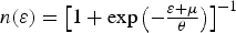 $n\lpar {\rm \varepsilon} \rpar = \mathop {\left[{1 + \exp\left({ - {\textstyle{{{\rm \varepsilon}+{\rm \mu} } \over {\rm \theta} }}} \right)} \right]}\nolimits^{ - 1}\!$ is the free electrons distribution function μ is the chemical potential. The bremsstrahlung cross section is calculated in the Born-Elwert approximation
 $$\eqalign{{\rm \sigma} ^{{\rm ff}} \lpar {\rm \omega} \rpar = 2.384 \times 10^6 {\textstyle{{{\rm \rho} Z_0^2 {\rm \theta} } \over {A{\rm \omega} ^3 }}}\vint\limits_{{\rm \varepsilon} _0 }^\infty \, n\lpar {\rm \varepsilon} \rpar \left[{1 - n\lpar {\rm \varepsilon} ^{\prime}\rpar } \right]g\lpar {\rm \varepsilon} ^{\prime}\comma \; {\rm \varepsilon} \rpar {\rm d}{\rm \varepsilon}\comma \; }$$
where ɛ′ = ɛ+ ω and
 $${\rm g}\lpar {\rm \varepsilon}^{\prime}\comma \; {\rm \varepsilon}\rpar = {\sqrt{3} \over {\rm \pi}} \sqrt{{{\rm \varepsilon}^{\prime} \over {\rm \varepsilon}}} \ln\left({\sqrt{{\rm \varepsilon}^{\prime}} + \sqrt{{\rm \varepsilon}} \over \sqrt{{\rm \varepsilon}^{\prime}} - \sqrt{{\rm \varepsilon}}} \right){1 - \exp \left[- 2{\rm \pi} Z_0 /\sqrt{2{\rm \varepsilon}^{\prime}} \right]\over 1 - \exp\left[- 2{\rm \pi} Z_0 /\sqrt{2{\rm \varepsilon}} \right]}.$$
The radiation field and level kinetics are accounted self-consistently by using an approach with interpolation between pre-calculated tables of spectral parameters.
Spectral absorption coefficients Kω and emissivities j ω are calculated using a collisional-radiative equilibrium model in quasi-stationary approximation for an optically-transparent plasma (radiation field U ω = 0) and for plasma in thermodynamic equilibrium with Planck's radiation field (U ω = U ωP) (Novikov & Solomyannaya, Reference Novikov and Solomyannaya1998):
 $$U_{\rm \omega} ^P=\displaystyle{{60} \over {c{\rm \pi} ^4 }}{\rm \sigma} \displaystyle{{{\rm \omega} ^3 } \over {\exp\lpar {\rm \omega} /T\rpar - 1}}\comma \;$$
where σ = 1.028 × 10⁻⁷ TW/cm2/eV4 is the Stefan–Boltzmann constant (here ω and T are measured in eV, c ≈ 3 × 1010 cm/s). It should be noted that the transparent plasma approximation comes to thermodynamic equilibrium at high densities (due to collisional processes) and gives the coronal equilibrium at low densities.
The ratio between calculated radiation field and Planck's radiation field is used as an interpolation parameter:
 $${\rm \zeta} \lpar z\comma \; t\rpar =\displaystyle{{\vint\limits_0^\infty \, U_{\rm \omega} \lpar z\comma \; t\rpar {\rm d}{\rm \omega} } \over {\vint\limits_0^\infty \, U_{\rm \omega} ^P {\rm d}{\rm \omega} }}.$$
Applying parameter ζ, the absorption coefficients Kω and emissivities j ω are calculated as follows:
 $$\matrix{ {{\rm \kappa} _{\rm \omega}=\lpar 1 - {\rm \zeta} \rpar {\rm \kappa} _{\rm \omega} ^{\lpar U_{\rm \omega}=0\rpar }+{\rm \zeta} {\rm \kappa} _{\rm \omega} ^{\lpar U_{\rm \omega}=U_{\rm \omega} ^P \rpar }\comma \; } \cr {\,j_{\rm \omega}=\lpar 1 - {\rm \zeta} \rpar j_{\rm \omega} ^{\lpar U_{\rm \omega}=0\rpar }+{\rm \zeta} j_{\rm \omega} ^{\lpar U_{\rm \omega}=U_{\rm \omega} ^P \rpar }\comma \;}}$$
where  ${\rm \kappa}_\omega^{(U_\omega = 0)}, j_\omega^{(U_\omega = 0)}$ are the absorption coefficients and emissivities for optically-transparent plasma, and
  ${\rm \kappa}_\omega^{(U_\omega = U_\omega^P)}, j_\omega^{(U_\omega = U_\omega^P)}$ are the absorption coefficients and emissivities for plasma in thermodynamic equilibrium.
After that two types of mean group absorption coefficients are calculated by using Rosseland R(ξ) = ξ4exp(−ξ)/[1 − exp(−ξ)]2, and Planck P(ξ) = ξ3exp(−ξ)/[1 − exp(−ξ)] weight functions:
 $${\rm \kappa} _{g_i }^R = \displaystyle{{\vint_{{\rm \xi} _i }^{{\rm \xi} _{i + 1} } \, R\lpar {\rm \xi} \rpar {\rm d}{\rm \xi} } \over {\vint_{{\rm \xi} _i }^{{\rm \xi} _{i + 1} } \, R\lpar {\rm \xi} \rpar /{\rm \kappa} _{\rm \omega} {\rm d}{\rm \xi} }}\comma \; {\rm \kappa} _{g_i }^P = \displaystyle{{\vint_{{\rm \xi} _i }^{{\rm \xi} _{i + 1} } \, P\lpar {\rm \xi} \rpar {\rm \kappa} _{\rm \omega} {\rm d}{\rm \xi} } \over {\vint_{{\rm \xi} _i }^{{\rm \xi} _{i + 1} } \, P\lpar {\rm \xi} \rpar {\rm d}{\rm \xi} }}.$$
The group emission coefficient is calculated as follows:
 $$\,j_{g_i } = \displaystyle{{\vint_{{\rm \xi} _i }^{{\rm \xi} _{i + 1} } \, j_{\rm \omega} {\rm d}{\rm \xi} } \over {{\rm \xi} _{i + 1} - {\rm \xi} _i }}.$$
Here ξ = ω/T, and the index g i denotes the heat radiation frequency range ωi ≤ ω ≤ ωi+1 for i = 1, … N g, where N g is the number of groups (N g = 96 in the presented below results).
Now, the system (12)–(14) can be written in a group approximation and transformed to the diffusion equation with appropriate boundary conditions so that
 $$\displaystyle{\partial \over {\partial z}}\left({ - \displaystyle{c \over {3{\rm \kappa} _{g_i }^R }}\displaystyle{{\partial U_{g_i } } \over {\partial z}}} \right)= 4{\rm \pi} j_{g_i } - {\rm \kappa} _{g_i }^P cU_{g_i }.$$
The tables of coefficients for CH2 are obtained by applying a mixing procedure of the tables for pure elements C and H. At given temperature the equality of chemical potentials (electron densities) of the mix components is suggested (Nikiforov et al., Reference Nikiforov, Novikov and Uvarov2005).
RESULTS AND DISCUSSION
Previously (Povarnitsyn et al., Reference Povarnitsyn, Andreev, Levashov, Khishchenko and Rosmej2012a), we have investigated the undesirable action of the long nanosecond prepulse on the target and the possible solution for the contrast improvement by means of a thin metal film. Initially, the transmission of the cold film is zero because of supercritical electron density and the prepulse does not reach the main target. Then, the expansion of the heated film starts resulting in the increase of energy absorption up to 100%, high temperatures and flat density profile ofthe plasma in front of the film. Eventually, the electron density in the film plasma drops below the critical value. Such undercritical plasma is now transparent for the laser beam. For different initial thicknesses of the film we observe various moments of transparency, and thus one can adjust the thickness so that the film becomes transparent at the moment of the main pulse arrival. In our numerical experiment, the laser pulse time profile is used in the form
 $$\eqalign{I\lpar t\rpar & = I_{\rm max} \left\{{C_{\rm ns} + C_{\rm ps} \exp\left[{ - \ln\lpar 16\rpar t^2 /{\rm \tau} _1^2 } \right]} \right.\left. {+\exp\left[{ - \ln\lpar 16\rpar t^2 /{\rm \tau} _0^2 } \right]} \right\}}$$
with I max = 1019 W/cm2, C ns = 10−6, C ps = 10−4, τ0 = 0.5 ps, τ1 = 20 ps and −2000 ≤ t ≤ 20 ps. This profile is typical for petawatt laser facilities (Bagnoud et al., Reference Bagnoud, Aurand, Blazevic, Borneis, Bruske, Ecker, Eisenbarth, Fils, Frank, Gaul, Goette, Haefner, Hahn, Harres, Heuck, Hochhaus, Hoffmann, Javorkova, Kluge, Kuehl, Kunzer, Kreutz, Merz-Mantwill, Neumayer, Onkels, Reemts, Rosmej, Roth, Stoehlker, Tauschwitz, Zielbauer, Zimmer and Witte2010), and the prepulse intensity level is of the order of 1013 W/cm2 that is sufficient for ionization of dielectrics during several picoseconds (Du et al., Reference Du, Liu, Korn, Squier and Mourou1994; Stuart et al., Reference Stuart, Feit, Rubenchik, Shore and Perry1995). Thus, we can use not only the metal Al film for target shielding but also a CH2 one. For the CH2 film, the Thomas–Fermi model (Fromy et al., Reference Fromy, Deutsch and Maynard1996) gives the mean ion charge 〈Z〉 = 1.12 at normal conditions that corresponds to preionized supercritical state.
The “optimal” thicknesses of Al and CH2 films are calculated in a set of simulations to be 400 and 2250 nm, respectively. As one can see in Figure 3 such films can diminish the level of transmitted intensity during the prepulse action while the main subpicosecond pulse can easily pass through the film plasma.
Fig. 3. (Color online) Intensity transmitted through the films. Solid (red) curve — 400 nm Al film; dashed (blue) curve — 2250 nm CH2 film; dashed-and-dot (black) curve — incident intensity of the laser pulse.
Nevertheless, as was previously shown the laser energy transformation into the soft X-ray radiation results in strong emission of the film plasma that causes the preheating of the main target. In Figure 4, the ratio of radiation flux integrated over the spectrum from 0 to 10 keV to the incident intensity, S(t)/I(t), is presented. The ratio can reach as much as 7% on the back side of the Al film (at t ≈ −700 ps) and up to 11% on the front side for the Al film (at moment t ≈ −1400 ps). As it is discussed below, this value is sufficient to produce a noticeable main target preheating, expansion, and ionization. Initial positions of the Al film and Ag bulk target are shown in Figure 5a. The gap between the film and the target is 600 µm. The target surface rarefaction is already noticeable by the moment t = −1000 ps. The target plasma interacts with the film plasma at t ≈ −200 ps and z ≈ 425 µm (peaks in panels a, b, and d). The characteristic temperature in the film plasma is about 900 eV. It is clearly seen in Figure 5a the subsequent decrease in electron density from a supercritical value (at t = −1000, −500, −200 ps) to an undercritical one at t = −100 ps. The ionization degree in Ag plasma reaches ≈25 and the extent of plasma is about 150 µm. At the same time the temperature of the bulk target is not larger than 1 eV, but the presence of extending plasma with a near-critical density can change the interaction of the main pulse with the target. Moreover, our 1D simulation can overestimate the temperature in the film plasma due to the laser spot size limitation and 3D nature of the plasma spread in experiment.
Fig. 4. (Color online) Thermal radiation flux in front (1) and back (2) directions for Al and CH2 films.
Fig. 5. (Color online) Evolution of the main parameters in the shielding Al film (400 nm) and the target of Ag (100 µm). Electron density normalized to the critical one — (a); mean charge of ions — (b); electron temperature — (c); ion temperature — (d). Instants: solid (black) curve — −1000 ps; dotted (blue) curve — −500 ps; dashed (green) curve — −200 ps; dash-and-dot (red) curve — −100 ps. Initial positions of Al film and Ag target are presented in panel (a).
In contrast to the situation considered, usage of the CH2 film gives approximately an order less intensity of the radiation flux (see Fig. 4), and as a result the relatively low preheating of the target is observed. During the prepulse action, even by the moment t = −100 ps the target rarefaction is negligible, see Figure 6a. The temperature of the target is of the order of 1 eV while the film substance is fully ionized by the moment t = −100 ps and the temperatures of electrons and ions are 400 and 40 eV, respectively.
Fig. 6. (Color online) The same, as in Figure 5 but for CH2 (2250 nm) shielding film.
The model of radiation transport gives the spectral distribution of photon energies. A comparison of the spectra of Al and CH2 is presented in Figure 7 and shows that aluminum plasma has a greater emissivity in the range from 0 to 900 eV. The maximum emission is produced by dense plasma of Al in the range 200–300 eV, while for the CH2 plasma the emission maximum is in the range 350–450 eV. The K α emission lines of Al are located at about 2 keV and do not give a noticeable contribution to the radiation energy flux. Thus, the application of thin films composed of light elements (CH, CH2, ect.) might be effective in the contrast modification and improvement.
Fig. 7. (Color online) Spectrum of re-emission from the back side of the films for moment t = −500 ps: Al — solid (red); CH2 — dashed (blue).
CONCLUSION
For the investigation of the dynamics of thin Al and CH2 films as well as the Ag bulk target irradiated by long nanosecond prepulses we have used the two-temperature single-fluid radiation hydrodynamic model. This model describes the laser energy absorption, electron-ion coupling and two-temperature effects, radiation transport, thermodynamic properties of materials. Using the model we have studied the action of a nanosecond prepulse on Al and CH2 films. The balance between the incident laser intensity, transmitted laser intensity and radiation flux is investigated in numerical experiment. The fraction of the laser energy transmitted through the film is determined together with the estimation of emitted thermal radiation flux.
We have found out that there is an “optimal” film thickness that can totally diminish the prepulse energy transmittance and become transparent by the moment of the main high-intensity subpicosecond laser pulse arrival. At the same time the re-emission of the prepulse energy by the shielding film can be significant for Al films producing an undesirable preheating and rarefaction of the main target placed behind the film. Fortunately, for a CH2 film it is observed a one-order less re-emission flux which does not produce an essential target disturbance. Thus, films composed of light elements can be effective in cutting of nanosecond low-intensity prepulses.
ACKNOWLEDGMENTS
The research was sponsored by the Russian Foundation for Basic Research (Project Nos. 13-08-01179, 11-02-91058, 11-08-01225, 13-08-12248 and 13-02-91057) and the Council of the President of the Russian Federation for Support of Young Russian Scientists and Leading Scientific Schools (Grant No. NSh-7241.2012.2).

