INTRODUCTION
In the field of pulsed power, intense electron-beam accelerators (IEBA) based on Tesla transformer has been researched widely (Katsuki et al., Reference Katsuki, Takano, Namihira and Akiyama2001; Liu et al., Reference Liu, Yin, Ge, Zhan, Cheng, Feng, Shu, Zhang and Wang2007, Reference Liu, Cheng, Qian, Ge, Zhang and Wang2009; Cheng et al., Reference Cheng, Liu, Qian and Zhang2009). It is widely used in a great variety of applications such as high power microwave generators (Korovin et al., Reference Korovin, Kurkan, Logino, Pegel, Polevin, Volkov and Zherlitsyn2003), X-ray generation (Tarasenko et al., Reference Tarasenko, Shunailov, Shpak and Kostyrya2005), treating of exhaust gas for industrial factories, sterilizing food and medicine (Mesyats et al., Reference Mesyats, Shpak and Yalandin1995), and so on. Tesla transformers that are used to resonantly step up the charging voltage are of great significance for getting high power and high repetitive rate which required in these applications.
Tesla transformer was originally proposed by Nikola Tesla. It can be either an air core transformer or a magnetic core transformer (Cheng et al., Reference Cheng, Liu, Qian, Zhang and Zhang2009). The air core transformer (Sarjeant et al., Reference Sarjeant and Rohwein1983) is lightweight, easy to construct and without saturation problem. However, it is not suitable for high repetition applications because of its low coupling coefficient and low energy conversion efficiency. Meanwhile, a transformer with magnetic core or bar is widely applied in high power pulse power field (Liu et al., Reference Liu, Yin, Ge, Zhan, Cheng, Feng, Shu, Zhang and Wang2007) due to its high coupling coefficient and high-energy conversion efficiency. By using such a transformer with magnetic core to producing short pulse, high power, and high repetitive rate electron beams has achieved great progress in the last two decades (Bykov, Reference Bykov1992; Korovin et al., Reference Korovin, Gubanov, Gunin, Pegel and Stepchenko2001).
So, in this paper, a high repetitive rate IEBA, which mainly consist of Tesla transformer (with a coaxial pulse forming line build-in), gas spark switch, and transmission line, is introduced in detail, especially on the design of the Tesla transformer and PFL. At last, some experiments is performed on the IEBA, and the IEBA is capable of producing electron beams of 300–700 kV/7–13 kA at repetitive rate 100 Hz, with the pulse width 35 ns.
THEORETICAL ANALYSES
The Construction of the IEBA and Tesla transformer
The IEBA consists of primary circuit, Tesla transformer, PFL, main switch, gas injector, transmission line, vacuum system and diode load, which is shown in Figure 1.

Fig. 1. (Color online) A schematic diagram of the IEBA.
Similar to Russian SINUS accelerators (Korovin et al., Reference Korovin, Gubanov, Gunin, Pegel and Stepchenko2001), the combination of Tesla transformer with coaxial pulse forming line is attractive to our application in two ways. First, the build-in transformer of the coaxial pulse forming line significantly decreases the total length and weight of the system. And second, the generator's high voltage components, such as inner cylinder conductor of coaxial PFL, are immersed into transformer oil, which is pressured and sealed in the pulse forming line, thus the insulation problem of the device is nicely solved and long lifetime of the device can be expected.
One operating cycle of this Tesla-type IEBA can be described as follows. First, the Tesla transformer produces a high-voltage pulse to charge the capacitor of pulse forming line. Then, an electric pulse of tens of nanoseconds (ns) is formed and delivered when the main switch with circulating high-pressure gas closes. Finally, an intense-current electric beam is produced after the electric pulse is transmitted to the diode.
The details of the PFL which build in Tesla transformer is schematically shown in Figure 2. It consists of primary windings, secondary windings, insulating support, open magnetic core, voltage input terminal, high voltage output terminal, outer cylinder of the PFL, and inner cylinder of the PFL. The primary winding is made from copper strip with a width of 150 cm, and the secondary windings are made of copper line, which is wound along a spiral groove on a tapered nylon stick. The transformer oil is filled in the supporting case to ensure electric insulation inside the transformer and server as the energy storage materials of the PFL.

Fig. 2. (Color online) Details of the pulse forming line with build-in Tesla transformer.
Charging Voltage of the PFL
The equivalent circuit of the charging progress can be shown as in Figure 3 (Liu & Winands, (Reference Liu and Winands2008)). In Figure 3, R p and R s are the resistance of the primary and secondary windings, respectively, L p1 and L s1 are the leakage inductance of the primary and secondary windings, respectively, C p and C s are the primary capacitance and PFL capacitance, respectively. M is the mutual-inductance between the primary and secondary windings. Assuming the primary capacitance (C p) is charged to V 0, the initial conditions for the circuit are I p(t = 0) = 0, I s(t = 0) = 0, in ideal case, i.e., R p = R s = 0, the voltage on secondary capacitance C s is readily solved:

Where
![\eqalign{{\rm \omega} _1&=\sqrt {\displaystyle{{\left({{\rm \omega} _p\!\, ^2+{\rm \omega} _s \!\, ^2} \right)+\left[{\left({{\rm \omega} _p \!\,^2 - {\rm \omega} _s \!\,^2} \right)^2+4k^2 {\rm \omega} _p \!\,^2 {\rm \omega} _s \!\,^2} \right]^{1/2}} \over {2\lpar 1 - k^2 \rpar}}} \cr {\rm \omega} _2&=\sqrt {\displaystyle{{\left({{\rm \omega} _p \!\,^2+{\rm \omega} _s \!\,^2} \right)- \left[{\left({{\rm \omega} _p \!\,^2 - {\rm \omega} _s \!\,^2} \right)^2+4k^2 {\rm \omega} _p\!\, ^2 {\rm \omega} _s \!\,^2} \right]^{1/2}} \over {2\lpar 1 - k^2 \rpar}}} \cr {\rm \omega} _p \!\,^2&=\displaystyle{1 \over {\left({L_p+L_{\,p1}} \right)C_p}}\comma \; {\rm \omega} _s \!\,^2=\displaystyle{1 \over {\left({L_s+L_{s1}} \right)C_s}}\comma \; k^2=\displaystyle{{M^2} \over {\left({L_p+L_{\,p1}} \right)\left({L_s+L_{s1}} \right)}}.}](https://static.cambridge.org/binary/version/id/urn:cambridge.org:id:binary:20151021092105787-0842:S0263034610000753_eqnU1.gif?pub-status=live)
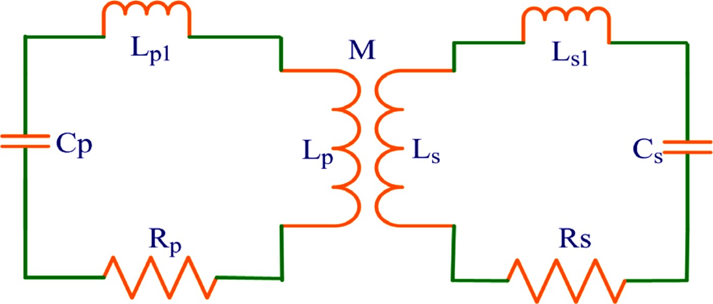
Fig. 3. (Color online) Equivalent charging circuit of the IEBA.
Let α = ωs2/ωp2 be the detuning coefficient between the primary and secondary circuit, we get the coupling coefficient
![k^2=1 - \displaystyle{{\left({1+{\rm \alpha}} \right)^2} \over {4{\rm \alpha}}}\left[{1 - \left({\displaystyle{{2n - 1} \over {2n^2 - 2n+1}}} \right)^2} \right]. \eqno\lpar 2\rpar](https://static.cambridge.org/binary/version/id/urn:cambridge.org:id:binary:20151021092105787-0842:S0263034610000753_eqn2.gif?pub-status=live)
The energy efficiency of the transformer is

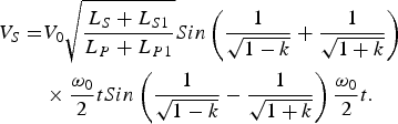
When ωp2 = ωs2 = ω02, i.e., α = 1, we get ![]() , so the secondary voltage is
, so the secondary voltage is
From Eq. (4), it can be conclude that when ![]() , N = 1, 3, 5…, and the corresponding coupling coefficients are 1.0, 0.6, 0.385…, secondary voltage gets maximal value.
, N = 1, 3, 5…, and the corresponding coupling coefficients are 1.0, 0.6, 0.385…, secondary voltage gets maximal value.
At early-stage, air-core Tesla transformers normally used have a coupling coefficient of 0.6 for achieving dual resonance conditions. However, dual resonance Tesla transformers provide their maximal output voltage in the second “half cycle” of the first output cycle, and the first half of the output cycle is naturally of opposite polarity to the second. The extended charging time and reversed polarity are two serious disadvantages to insulation, especially in case of repetition applications.
By introducing magnetic cores into a Tesla transformer, coupling between the primary and secondary windings will be enhanced, as a result, the coupling coefficient k can be as close as to 1.0. In this case, the transformer provides its maximal voltage in the first “half cycle,” thus charging time of the pulse forming line is significantly decreased. And the Tesla transformer is very similar to a well-coupled high voltage transformer.
Length of the Tesla Transformer and PFL
As shown in Figures 2 and 4, transformer consists of two magnetic cores, one inner magnetic core, and one outer magnetic core. The open magnetic cores are not continuous along magnetic path. These two magnetic cores serve simultaneously as the inner and outer conductors of the coaxial pulse forming line. Under carefully designing of the parameters of the primary and secondary electro-circuit, the energy efficiency of Tesla transformer can be increased remarkably.

Fig. 4. Structural sketch of the magnetic cores, (a) outer magnetic core; (b) inner magnetic core.
The specific design of structure should be based on the breakdown strength of the dielectric material, as well as the insulating requirement of crucial parts. Figure 5 shows the withstand voltage and storing energy, respectively, dependent on the structural factor. The relationship between the maximal withstand voltage of Tesla transformer and coaxial-line radius expressed as bellows:
where, U F is the voltage of PFL, E b is the breakdown strength of PFL's dielectric material, r 2 is PFL's outer radius, β is the structure factor, β = ln(r 2/r 1), It can be easily demonstrated that β = 2πZ Fɛ1/2/Z 0, Z F is the characteristic impedance of PFL, ɛ is the dielectric constant of the insulating material, and Z 0 is the characteristic impedance in free space.

Fig. 5. (Color online) PFL's storing energy and withstand voltage dependent on its structural factor.
Since the output requirements and the insulating material are fixed, the Tesla transformer's structure is dependent only on Z F. If Z F is also fixed, the minimal structure for Tesla transformer can be obtained. From Eq. (5), we can deduce that when β = 1, r 2 is minimized.
When the structure factor is fixed, the energy storing in per unit length is dependent on r 22 as bellows:
The selection of value Z F is related to not only the output parameter of Tesla transformer, but also the impedance values of PFL and diode load. The geometric length of Tesla transformer is designed by the required pulse length, which is given in Eq. (7),
Where l is the geometric length, τ is the pulse width, ɛ is the dielectric constant of the insulating material, c is the light velocity in vacuum.
Magnetic Core
Russian scientists indicated that if the coupling coefficient is close to 1, that is, 1-k«1, then k can be expressed (Korovin, (Reference Korovin1988)) as fellow:
Where, F(ρ) = (ρ – 1)(2ρ + 1)/ρ2 is the structure function, ρ = r 2/r 1, β = lnρ, l k is the longitudinal length of both the primary and secondary windings, l T is the magnetic core's length.
From Eq. (8), as the magnetic core's length l T is given, k reaches maximal value if l k is half of l T. The primary winding is designed as single turn with the same radius of that of the PFL. For β = 1, we have Z F = 40Ω. The relationship between k and l T/2r 2 is given in Figure 6. It reveals that k increases with l T/2r 2, for example when l T is five times greater than r 2, the coupling coefficient k > 0.9.

Fig. 6. Coupling coefficient dependent on aspect ratio of open magnetic core.
The cross section of magnetic core can be described as:
Where u F is the maximal charging voltage of secondary capacitor, t ch is the charging time, ΔB max is the maximal amplitude of magnetic induction, and n 2 is turns of the secondary winding.
The charging time of PFL can be expressed as:
Where, C p = n 22C s, n 1 is the primary winding's turn, C s is the capacitance of PFL, for a coaxial PFL, clearly ![]() is the leaking inductance of the primary winding.
is the leaking inductance of the primary winding.
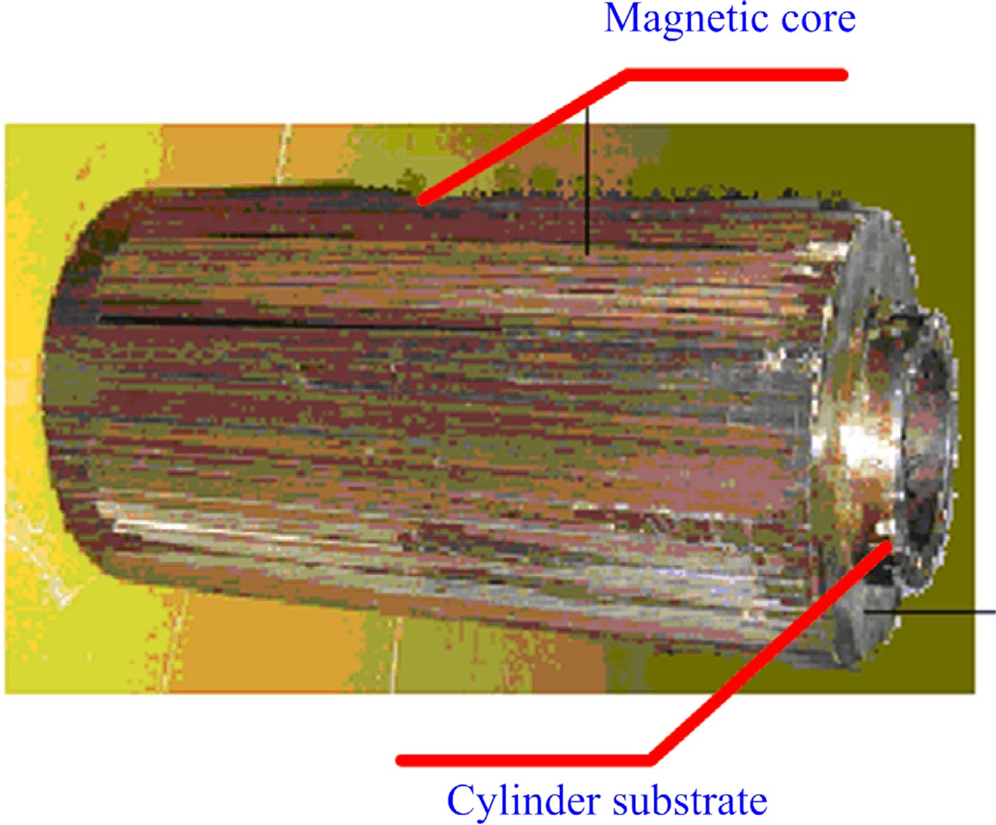
The performance of magnetic core is determined by magnetic material and fabricating process. First, the material with less eddy loss should be chosen for magnetic core. A sort of magnetic material typed DG6 has been adopted. The thickness of DG6 ribbon is no more than 0.1mm. The preproduction model of inner magnetic core is shown in Figure 7.

Fig. 7. (Color online) Preproduction model of inner magnetic core.
Primary and Secondary Circuits
Tesla transformer is a kind of voltage-amplifying device. There are two oscillating frequencies determined by inductance and capacitance in the primary and secondary circuits in the Tesla transformer, which is shown in Figure 3.
From Eq. (3), the energy efficiency of the transformer reaches maximal value as the detuning coefficient α up to 1. Hereby, the primary oscillating frequencies ωs approximate to the secondary oscillating frequencies ωp in designing.
Once Z F and pulse length are given, the secondary capacitance will be decided, C s = τ/Z F. So the primary capacitance could be chosen as C p = C sn 22/n 12, in which n 1 and n 2 are numbers of primary and secondary windings, respectively. Clearly, there are a series of C p with the n 2 variety. In a general way, the charging voltage range of the primary capacitance should be no more than one kilovolt which will be advantageous for primary circuit insulation in air.
PARAMETERS OF THE IEBA
Through the analysis above, according to the need of the IEBA, the main parameters of the PFL, Tesla transformer can be obtained easily. The structure of the IEBA based on PFL with a built-in Tesla transformer is shown in Figure 1, and the parameters of the IEBA are introduced as below.
The diameters of the outer and inner conductors are 700 mm and 256 mm, respectively. This results in a 40Ω output impedance of the PFL. The length of the line is 3500 mm, which generates a pulse length of 35 ns. So, according to C s = τ/Z F, the capacitance of the PFL is about 437 pF.
For the primary electro-circuit of the IEBA, in order to decrease the charging voltage, the number of turns of the primary winding is 1 and the range of charging voltage is 600–1000 V. Thanks to the capacitance of the PFL is about 437 pF, the primary capacitance (Cp) is about 2 mF. In order to obtain an output voltage of the Tesla transformer up to 1.4 MV, the number of the second winding is 2500. The magnetic core's section area is about 200 cm2.
EXPERIMENTAL RESULTS AND DISCUSSION
Figure 8 shows the experimental result of the designed Tesla transformer. The secondary voltage of Tesla transformer increases with the primary voltage, and the ratio of secondary and primary voltage is about 1845, smaller than the ratio of windings. The differences of ratios mostly root in resistance of the primary cycle.

Fig. 8. Secondary voltage increasing with primary voltage.
Short pulse has been generated when Tesla transformer working together with gas gap switch. Gas (N2) gaps are preferable at high pulse-repetition rates when the recovery time must be short. At pulse-repetition rate of the accelerator increases up to 10 Hz, the operation of the high-voltage gas switch is of high jitter. So the gas switch need quickly sweep away the discharge by-products from the gap. One three-electrode repetition gas trigatron switch is applied to discharge PFL. The breakdown characteristics of trigatron switch are influenced by gas pressure, percent of self-breakdown, gas flow speed, and field enhancement factor. The experimental results prove that the switch can operate steadily at voltage up to 1. 1 MV, peak current up to about 13.7 kA, and repetitive rate up to 100 Hz. Figure 9 shows experimental waveforms of secondary voltage, which is also the charging voltage of PFL, when the accelerator is operating at the frequency of 100 Hz.

Fig. 9. Secondary voltage waveforms of the transformer in 100 Hz.
With an intense relativistic electronic beam diode load, the diode voltages and current have been measured by a capacitance potentiometer designed at the end of PTL and a Rogowski coil located at transect of diode gap. The envelop waveforms of diode voltage and current is shown in Figure 10. It is clearly shown that output voltage of the IEBA at the diode is about 550 kV, the current is 11 kA, the duration is 35 ns, the power is 6 GW, and the waveforms of the voltage or current overlapped well.

Fig. 10. The envelop waveforms of diode in 100 Hz.
CONCLUSIONS
A high repetitive rate IEBA based on high coupling Tesla transformer is designed with open magnetic cores. After optimization for the primary and secondary circuitries' parameters, the factual energy transmission efficiency reaches 83%, and can continuously operate at 100 Hz frequency, the accumulated number of output pulses is over 600,000.
The constant-current charging technology is applied to the primary charging supply for Tesla transformer. So, the Tesla transformer provides high voltage adjustable. Using this kind charging technology, the charging energy's efficiency increases and the stability of output voltage is enhanced. The experimental results show that the high repetitive rate IEBA is capable of producing electron beams of 300 – 700 kV/7–13 kA at repetitive rate 100 Hz, with the pulse width 35 ns.