Introduction
A new scheme has been proposed that utilizes high-energy electron beams as a probe for time resolved imaging measurements of high-energy density materials, especially for high-energy density matter and inertial confinement fusion (ICF) (Gai et al., Reference Gai, Qiu and Jing2014; Zhao et al., Reference Zhao, Zhang, Xu, Zhan, Gai, Qiu, Cao and Tang2014b, Reference Zhao, Zhang, Gai, Du, Cao, Qiu, Zhao, Cheng, Zhou, Ren, Huang, Tang, Xu and Zhan2016b). High Energy Density Physics aims to study the properties of matter under extreme temperature and pressure conditions, which is also called Warm Dense Matter (WDM) (Sharkov et al., Reference Sharkov, Hoffmann, Goluber and Zhao2016). According to WDM properties, the high-energy density exceeds 1 Mbar transiently produced in the laboratory on the 10 ns to 1 µs time scale. A diagnostics system should have a large dynamic range and high-spatial resolution. Compared to proton and other X-ray diagnostics methods, electron radiography systems based on photo-injector linear electron accelerator (LINAC) promises high-gain spatial and temporal resolution at lower cost. High-energy electron radiography (HEER) was first developed by Los Alamos National Lab (Merrill et al., Reference Merrill, Harmon, Hunt, Mariam, Morley, Morris, Saunders and Schwartz2007) with a 30 MeV electron beam achieving spatial resolution on the order of 100 microns. The first picosecond pulse-width HEER experiment was demonstrated by the Institute of Modern Physics (IMP), Chinese Academy of Sciences (CAS), and Tsinghua University (THU), based on THU LINAC (Zhao et al., Reference Zhao, Cao, Cheng, Shen, Zhang, Zhao, Gai and Du2014a, Reference Zhao, Cao, Liu, Shen, Wang, Zong, Zhang, Jing, Cheng, Zhao, Zhang, Du and Gai2016a; Zhou et al., Reference Zhou, Du, Cao, Zhang, Huang, Chen, Cheng, Chi, Liu, Su, Tang, Tian, Wang, Wang, Xiao, Yan, Zhao, Zhu, Zhou, Zong and Gai2017) with a 46 MeV beam and spatial resolution better than 10 microns, demonstrating proof of principle that this kind of LINAC with ultra-short pulse electron bunch can be used for HEER.
For ICF target diagnostics, it is essential to measure the target's moving boundary during compression to clearly distinguish the density distribution. The image intensity distribution information is important for the diagnostics of target density distribution. In order to confirm the HEER diagnostic ability to generate the required density distribution, different materials of the same thickness and target area density have been imaged and analyzed. Although there are some discrepancies between experimental and theory analysis, the results show that the density distribution can be attained from HEER. The reason for this discrepancy is investigated and the importance of the uniformity in the transverse beam distribution illuminating the target is proved.
Furthermore, the method for generating the uniform transverse beam distribution with octupole magnets was studied and verified by simulations, which is important for the diagnostics with image contrast information. This paper will focus on the importance of the image intensity information from experimental result analyses and the method to generate the transversely uniform electron beam illuminating the target, which is critical for density distribution diagnostics.
HEER principle and beam target interaction theory introduction
The principle of HEER
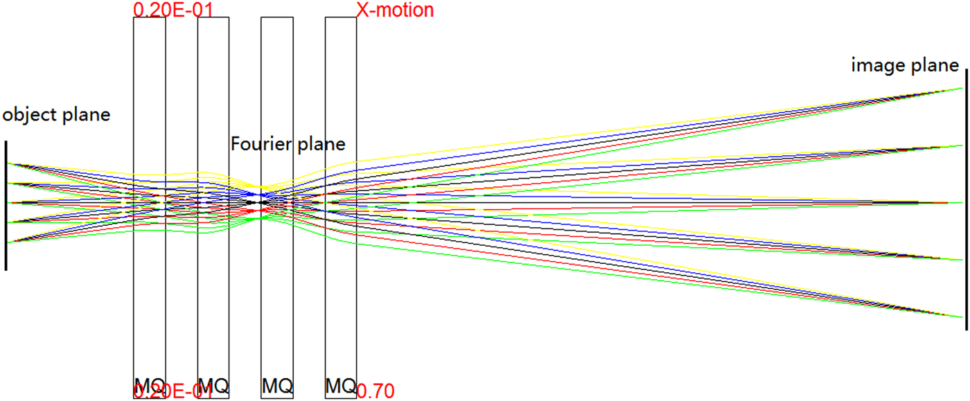
Charged particle radiography (CPR) (Morris et al., Reference Morris, King, Kwiatkowski, Mariam, Merrill and Saunders2013) is a benefit of the magnet lens optics, which improves the spatial resolution dramatically compared to projection radiography. HEER provides a similar diagnostic tool. The principle of CPR is shown in Figure 1: the charged particles pass through the target and then are imaged point to point from the target plane to image plane by the imaging lens. There are two primary requirements of any CPR lens system. First, the lens must provide point-to-point focus from object to image. Second, it must form a Fourier plane, where particles are radially sorted by the magnitude of the scattering within the object. With this correlation, particles scattered to large angles by multiple Coulomb scattering can be removed through collimation at the Fourier plane. The remaining parameters of a particular CPR lens system design are determined by the radiographic applications. The beam energy must be high enough to penetrate the areal density of the object to be radiographed, and the aperture of the lens system must be chosen to provide sufficient angular acceptance throughout the required field of view. An additional strong design requirement is the resolution of the radiography system. This resolution is typically dominated by chromatic aberrations due to energy spread of the injected beam in combination with the spread of energy loss through the object due to areal density variations of the object.

Fig. 1. Mapping of the charged particle (electron) radiography in the x plane with magnification.
High-energy electron beam target interaction
The important interaction processes between electrons and samples are multiple Coulomb scattering (MCS), ionization energy loss, radiative energy loss, and bremsstrahlung (Patrignani et al., Reference Patrignani, Agashe, Aielli, Amsler, Antonelli, Asner, Baer, Banerjee, Barnett, Basaglia, Bauer, Beatty, Belousov, Beringer, Bethke, Bichsel, Biebel, Blucher, Brooijmans, Buchmueller, Burkert, Bychkov, Cahn, Carena, Ceccucci, Cerri, Chakraborty, Chen, Chivukula, Copic, Cowan, Dahl, D’Ambrosio, Damour, de Florian, de Gouvˆea, DeGrand, de Jong, Dissertori, Dobrescu, D’Onofrio, Doser, Drees, Dreiner, Dwyer, Eerola, Eidelman, Ellis, Erler, Ezhela, Fetscher, Fields, Foster, Freitas, Gallagher, Garren, Gerber, Gerbier, Gershon, Gherghetta, Godizov, Goodman, Grab, Gritsan, Grojean, Groom, Grünewald, Gurtu, Gutsche, Haber, Hagiwara, Hanhart, Hashimoto, Hayato, Hayes, Hebecker, Heltsley, Hernández-Rey, Hikasa, Hisano, Höcker, Holder, Holtkamp, Huston, Hyodo, Irwin, Jackson, Johnson, Kado, Karliner, Katz, Klein, Klempt, Kowalewski, Krauss, Kreps, Krusche, Kuyanov, Kwon, Lahav, Laiho, Langacker, Liddle, Ligeti, Lin, Lippmann, Liss, Littenberg, Lugovsky, Lugovsky, Lusiani, Makida, Maltoni, Mannel, Manohar, Marciano, Martin, Masoni, Matthews, Meißner, Milstead, Mitchell, Molaro, Mönig, Moortgat, Mortonson, Murayama, Nakamura, Narain, Nason, Navas, Neubert, Nevski, Nir, Olive, Pagan, Parsons, Peacock, Pennington, Petcov, Petrov, Piepke, Pomarol, Quadt, Raby, Rademacker, Raffelt, Ratcliff, Richardson, Ringwald, Roesler, Rolli, Romaniouk, Rosenberg, Rosner, Rybka, Ryutin, Sachrajda, Sakai, Salam, Sarkar, Sauli, Schneider, Scholberg, Schwartz, Scott, Sharma, Sharpe, Shutt, Silari, Sjöstrand, Skands, Skwarnicki, Smith, Smoot, Spanier, Spieler, Spiering, Stahl, Stone, Sumino, Sumiyoshi, Syphers, Takahashi, Tanabashi, Terashi, Terning, Thorne, Tiator, Titov, Tkachenko, Törnqvist, Tovey, Valencia, Van de Water, Varelas, Venanzoni, Vincter, Vogel, Vogt, Wakely, Walkowiak, Walter, Wands, Ward, Wascko, Weiglein, Weinberg, Weinberg, White, Wiencke, Willocq, Wohl, Wolfenstein, Womersley, Woody, Workman, Yao, Zeller, Zenin, Zhu, Zimmermann and Zyla2017). The MCS, ionization energy loss, and straggling processes in electron radiography are very similar to those in proton radiography, an analogous process and well understood radiography technique used around the world for thick object imaging (Morris et al., Reference Morris, Brown, Agee, Bernert, Bourke, Burkett, Buttler, Byler, Chen, Clarke, Cooley, Gibbs, Imhoff, Jones, Wiatkowski, Mariam, Merrill, Murray, Olinger, Oro, Nedrow, Saunders, Terrones, Trouw, Tupa, Vogan, Winkler, Wang and Zellner2016). However, bremsstrahlung interactions are dominant in the formation of electron radiography when the electron-beam energy is above the critical energy. The scattering angle distributions and the energy spectrum of the electron beam after passing through the target are important considerations for HEER.
A charged particle traversing a medium is deflected by many small angle scatterings. These scatterings are due to the Coulomb field of atoms and are assumed to be elastic. In each scattering the energy of the particle is constant but the particle direction changes. In the simplest model of multiple scatterings we ignore large angle scatters. The scattering angle distribution is approximated by MCS and Gaussian distribution with an rms width ϕ 0(t):
 $$f\,(t,{\phi} ) = \displaystyle{1 \over {{\phi} _0(t)\sqrt {2{\rm \pi}}}} e^{ - (1/2){({\phi} /({\phi} _0(t)))}^2}$$
where
 $${\phi} _0(t) = \displaystyle{{13.6\,{\rm MeV}} \over {{\beta} _{\rm c}p}}\sqrt t (1 + 0.038\,\ln (t))$$
Here, p, β c, and t = x/X 0 are the momentum, velocity, and the thickness of the scattering medium in radiation lengths. The rms width ϕ 0(t) is shown in Figure 2(a) as a function of thickness t for different beam energies 40, 100, 300, and 1000 MeV from formula (1). Figure 2(b) shows the scattering angle distribution of 40 MeV beam for different thicknesses t from formula (2). For the same electron-beam energy and when the target becomes thicker, the scattering angle increases. Electrons with large scattering angles will be filtered out by the collimator at the Fourier plane.
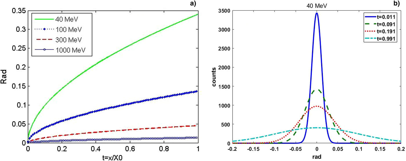
Fig. 2. (a) rms widths ϕ 0(t) as a function of thickness t for different beam energies and (b) scattering angle distribution of 40 MeV beams for different thicknesses t.
The energy spectrum after electrons pass through the target can be approximated by ionization energy loss and radiative energy loss (Mejaddem et al., Reference Mejaddem, Belkic, Hyodynmaa and Brahme2013). For the electron beam, when the energy is below critical energy, the collision stopping power is the main reason for energy loss, but when the beam energy is above the critical energy, the energy loss is dominated by radiative stopping power. Electron energy straggling is described as ionization energy losses, which could be described by Landau distribution, Blunck–Leisegang distribution, and Vavilov distribution according to the electron energy and material thickness. Also electrons lose their energy in the process of bremsstrahlung production as a result of interactions with the field of the nucleus. For thicker targets, the electromagnetic cascades are initiated by high-energy electrons; the energy distribution has been researched by Y.T. Tsai (Tsai and Whitis, Reference Tsai and Whitis1966). For our present target and beam energy used in our experiment, the thickness is about 10 microns; therefore the energy loss is very small and may be neglected. The imaging is dominated by the scattering angle distribution.
Experimental analyses of the requirements of the transverse uniform distribution beam
In the HEER experiment, the beam energy is 46.3 MeV, bunch charge is about 100 pC, the emittance is about 2 mm mrad, beam spot size is 3 mm, the bunch length is about 1 ps, and the beam momentum spread is less than 1%. The lens consists of two triplets. By tuning the imaging lens quadrupole strength, the three samples, 50 mesh square Ni grid, 75 mesh hexagon Cu grid, and 200 mesh square Cu grid, are well radiographed as shown by the images in Figure 3. Detailed experimental set up, results, and analysis can be found in Zhao et al. (Reference Zhao, Cao, Cheng, Shen, Zhang, Zhao, Gai and Du2014a), which indicates that HEER is effective and has high-spatial resolution, better than 10 µm.

Fig. 3. HEER imaging of the samples: (a) 50 mesh Ni grid, (b) 75 mesh Cu grid, and (c) 200 mesh Cu grid.
Further experiments were performed in order to investigate the HEER ability to diagnose the aerial density of the target. The target design and installation is shown in Figure 4: target 1 is the different material strips with the same aerial density, as a standard of gold strip with a thickness of 5 µm, which means the aerial density is 9.65 mg/cm2; target 2 consists of different material strips all with the same thickness of about 10 µm. The size of the squared hole for installing the target is about 6 × 6 mm2 and for each strip the width is about 1 mm. The imaging magnet lens was tuned under the imaging conditions rendering the grid image shown in Figure 3.
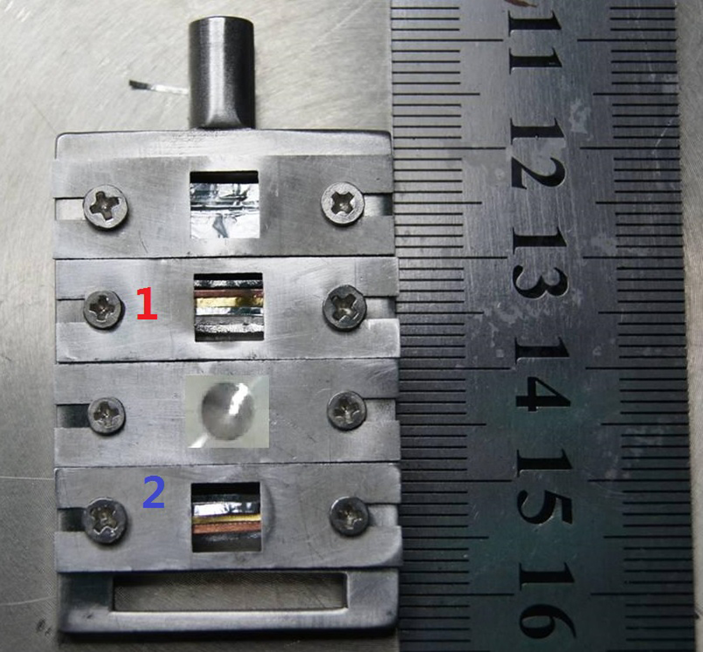
Fig. 4. Target installations in the experiment: target 1 strips with the same area density but different material and target 2 strips with the same thickness but different material.
The experimental data are analyzed by subtracting the background. First the target images obtained by HEER minus the image without beam and then dividing the beam image at the imaging plane under imaging conditions without target. The results are shown in Figure 5 for target 1 and in Figure 6 for target 2.

Fig. 5. The experimental results for target 1 and strips with the same area density but different material.
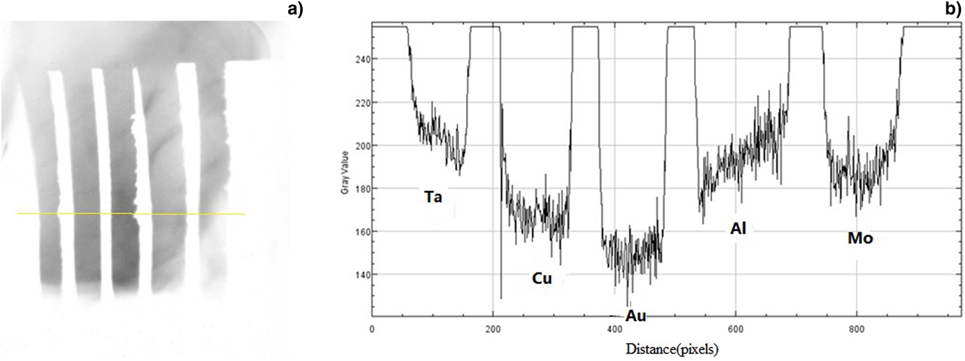
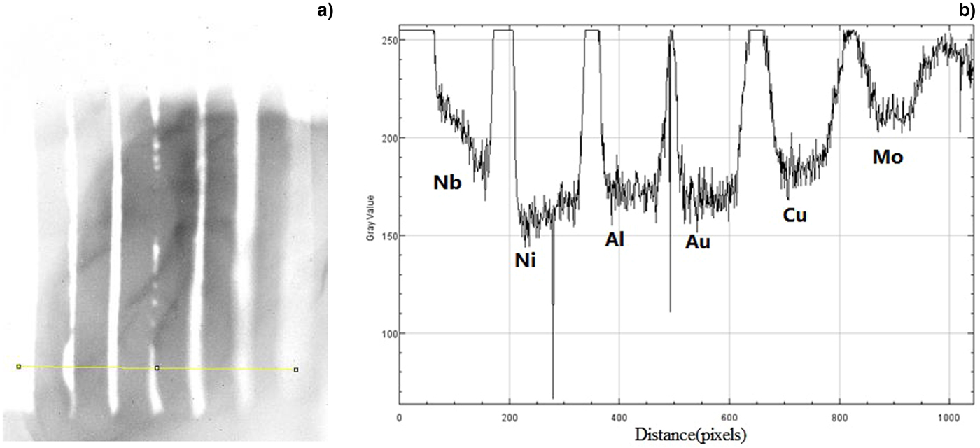
Fig. 6. The experimental result of target 2 and strips with the same thickness but different material.
The strips in target 1 are made of different materials but all with the same area density. Figure 5(b) shows the analyzed image intensity of the radiography images taken of the same areal density but different material strips (corresponding to gold strip with a thickness of 5 µm). For the Ni, Al, Au, and Cu strips, the intensity does not differ much. This is reasonable because of the same aerial density and the scattering angles are the same according to formulae (1) and (2) under the same imaging conditions. This is not the case for Nb and Mo.
The strips in target 2 are also made of different materials but all with the same 10 micron thickness. The analyzed radiography results consisting of the HEER image intensity for different material strip targets are shown in Figure 6(b). For high-density materials the intensity is low because of large scattering according to formulae (1) and (2), which is reasonable for Ta, Cu, and Au. However, this is not the case for Al and Mo.
For the experimental results described above, there are some discrepancies for the strips placed at the margin of the beam. The beam transverse density distribution in the image plane without target was recorded under the imaging lens under the imaging conditions. Figure 7 shows the observed non-uniform distribution. Due to the beam transverse distribution, the object plane is imaged on the imaging plane by the imaging lens. The beam transverse distribution without target at the imaging plane corresponds to the beam transverse distribution at the object plane, indicating that the illuminating beam at the target is not uniform having significant influence on the experimental results. In one method the image is processed with subtracting the background and dividing the beam image at image plane without target. From data analysis, we also found the beam position is not stable from shot to shot, which has an effect on the imaging process for background subtraction. Due to non-uniform beam and beam position jittering, the experimental results do not fully agree with the theory analysis. The beam position jittering depends on the LINAC and is very difficult to improve. Therefore the best case for imaging is single shot with transverse uniform distribution beam illuminating the target, by which the target aerial density distribution can be imaged more reasonable.
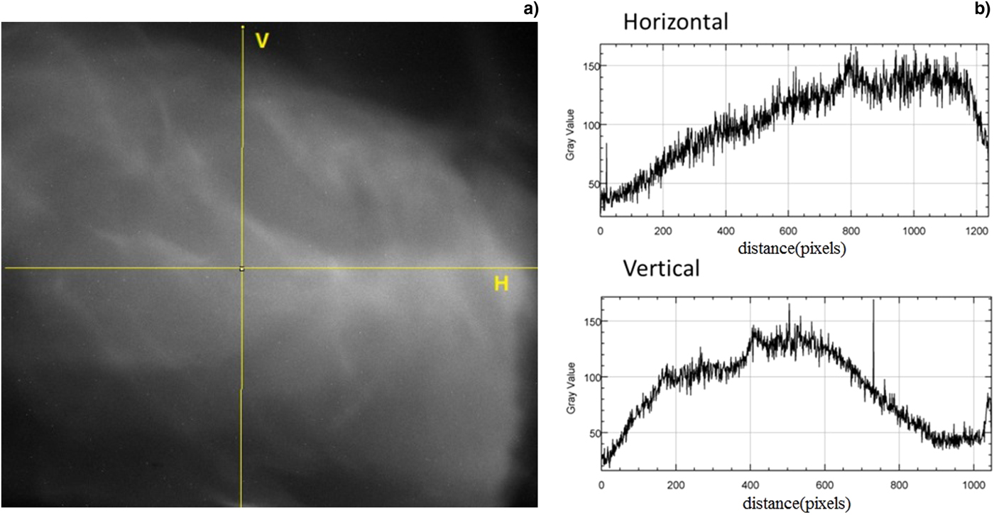
Fig. 7. Beam transverse intensity distribution at the imaging plane without target under imaging conditions: (a) beam image at imaging plane and (b) intensity distribution along the V (vertical) and H (Horizontal) lines.
Transverse uniform beam generating method and simulation studies
From the above experimental results, it is found that for the diagnostics of target aerial density, the image contrast and relative intensity distribution are critical. To get acceptable image contrast and intensity information, the illuminating beam must be transversely uniform distributed at the object plane which has less effect on the image contrast information. In charged particle beam applications, uniform irradiation is frequently utilized to bring homogeneous irradiation effects over a sample with a large area or on a large number of samples simultaneously. Three types of methods are widely used for generating the uniform irradiation field: beam scanning method, beam expansion method with scatters, and by means of nonlinear focusing method like octupole magnets (Meat and Aniel, Reference Meat and Aniel1996). For the scanning method, the local particle fluency rate is not continuous and not suitable for HEER; for the scattering method, the uniformity is not high and the beam will increase the momentum spread and emittance due to the scattering and energy loss, which is also not good for HEER. In these studies, we adopt the third method using an octupole magnet to generate uniform irradiation beam on the target. The theory of uniformization of the transverse beam profile by means of nonlinear focusing method is detailed in Yuri et al. (Reference Yuri, Miyawaki, Kamiya, Yokota, Arakawa and Fukuda2007) while some experimental studies are confirmed using this method in Yuri et al. (Reference Yuri, Ishizaka, Yuyama, Shibori, Okumura and Yoshida2011).
Beam matching in HEER is nominally done using a matching line upstream of the imaging lens section for beam angle position correlation tuning and for producing large enough beam size illuminating the target. We use this beam line by adding two octupoles to generate the uniform beam at the target position. For simulation studies we use the following initial beam parameters: beam energy: 40 MeV, bunch charge: 1 nC, emittance: 2 mm mrad, bunch length: 1 mm, beam radius: 1 mm, transverse and longitudinal with Gaussian distribution. The x–y transverse distribution, intensity distribution along x, x–x′, and y–y′ phase space distribution are shown in Figure 8(a–d), respectively. The simulation is done with the GPT code (GPT code, 2017) and self-edited octupole magnet field distribution according to sextupole and quadrupole model in GPT.

Fig. 8. The initial beam distribution for simulation studies: (a) beam x–y distribution, (b) beam x projection, (c) x–x′ phase space distribution, and (d) y–y′ phase space distribution.
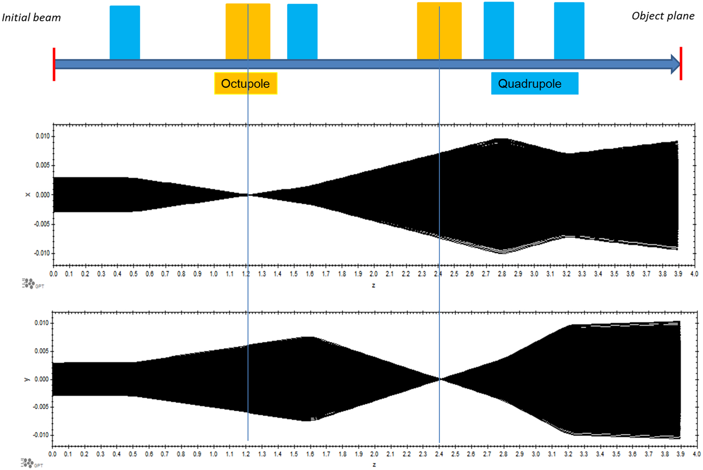
The matching beam line is shown in Figure 9 and the parameters are shown in Table 1, the total length is 3.9 m. Since the initial beam angle-position correlation (phase space orientation) is arbitrary, the beam matching line design only considers beam size sufficiently large to illuminate the target. Four quadrupoles are used for beam matching to the target shown in Figure 9. With the strength shown in Table 1, the beam trajectories are shown in Figure 9 for x and y planes respectively. With these settings, the beam illuminating area still preserving a Gaussian distribution, is about 10 mm × 10 mm is shown in Figure 10(a). Figure 10(b) shows the x plane and (c) the y plane.

Fig. 9. Beam optics layout and trajectories (octupoles off) in the x plane and y plane for the matching beam line.
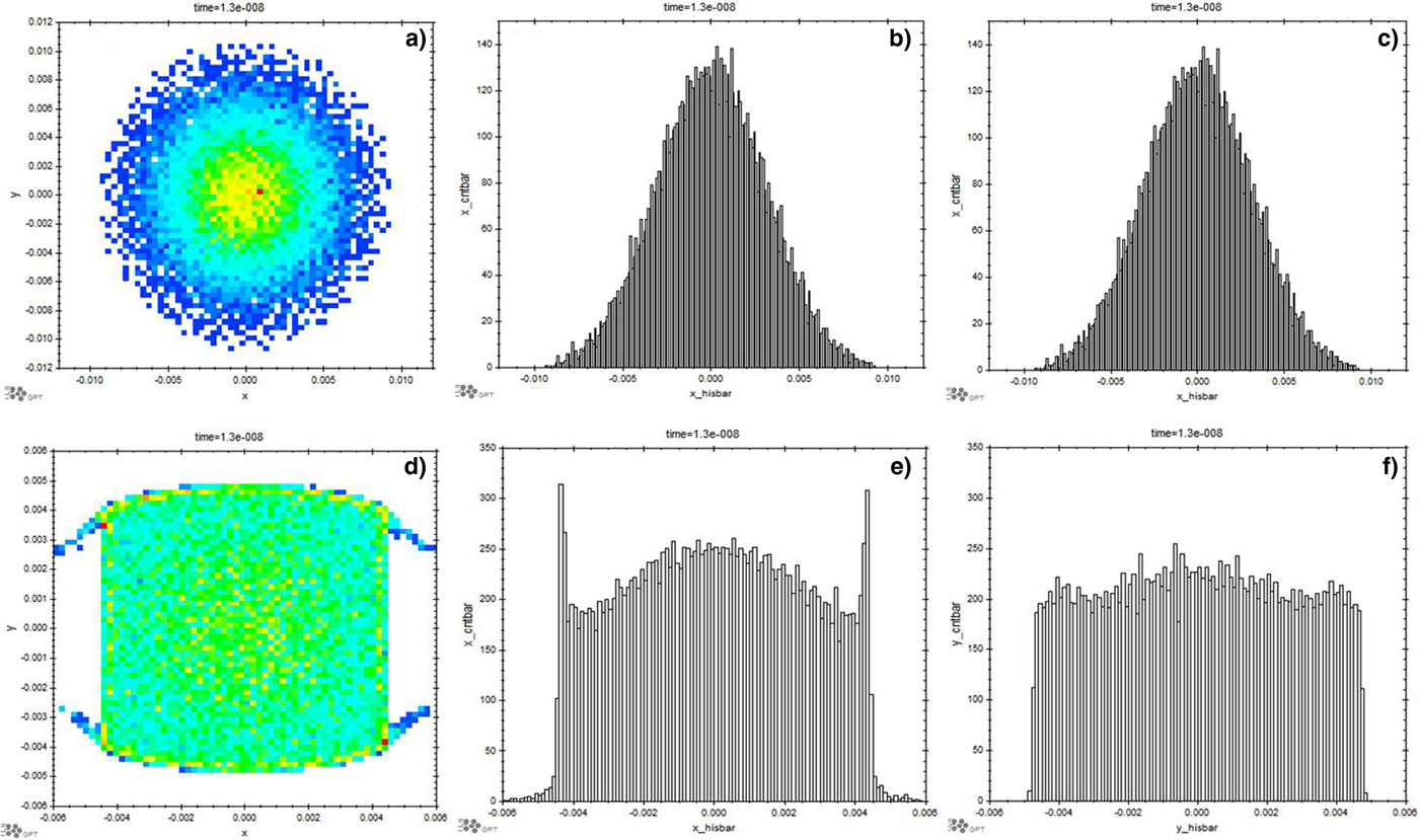
Fig. 10. Beam transverse distribution at the target position (object plane) without octupole: (a) transverse distribution and (b and c) projection of (a) in the x and y planes and with octupole, (d) transverse distribution, (e and f) projection of (d) in the x and y planes.
Table 1. The matching beam line layout and parameters (total length is 3.9 m)

In order to generate the two-dimensional uniform distribution, we must consider the particle motion in both transverse directions. In fact, the octupole field will couple the horizontal and vertical motion; such a coupling complicates the particle motion and is not preferable for practical use. Furthermore, individual adjustment of octupole is desirable for practical ease of operation. Therefore, two octupoles were added to the beam line at separate location as shown in Figure 9. The octupoles are placed where the beam cross-section is flat to make the coupling as weak as possible. As shown in Figure 9, one octupole is placed at the x plane beam waist but the y beam envelope is large and vice versa for the other octupoles. The octupole strength is inferred from theoretical calculations (Yuri et al., Reference Yuri, Miyawaki, Kamiya, Yokota, Arakawa and Fukuda2007), and then tuned individually in the simulations to obtain a two-dimensional uniform beam distribution. The found octupole strengths are shown in Table 1 and the corresponding beam distributions are shown in Figure 10(d) x–y distribution, (e) x plane projection, and (f) y plane projection, from which the uniform transverse beam is easily observed. On comparison between Figure 10(a–c) and (d–f), with two octupoles the Gaussian transverse distribution beam can be transformed to a uniform distribution very well.
Beam matching is very important for HEER as detailed in Zhao et al. (Reference Zhao, Cao, Liu, Shen, Wang, Zong, Zhang, Jing, Cheng, Zhao, Zhang, Du and Gai2016a). It is shown that the beam angle-position correlation has an effect on the spatial resolution. The beam angle-position correlation matching with the imaging lens parameters is easily achievable with the beam matching line. For example, tuning the quadruple strength in a four-quadrupole beam matching line, the beam phase space orientation and beam size can be adjusted to meet the requirements. To generate a uniform beam, the octupoles are added to the matching beam line. Therefore, the phase space changes due to octupoles must be considered carefully. The phase space at the target with the above beamline is shown in Figure 11(a) x–x′, (d) y–y′ without octupoles and (b) x–x′, (d) y–y′ with octupoles. It is clearly shown how the nonlinear field affects the phase space distribution. The beam uniformization discussed with the octupole field results from folding the tails of a Gaussian distribution in the phase space. The x plane shown in Figure 11(c) is the overlap of Figure 11(a) and (b). Using the same scale it can be seen that the phase space in the center part of the beam, shown between two red lines, does not change due to the octupoles. This is also true for the y plane shown in Figure 11(f). Therefore, the octupoles will not change the center part of the beam phase space orientation.
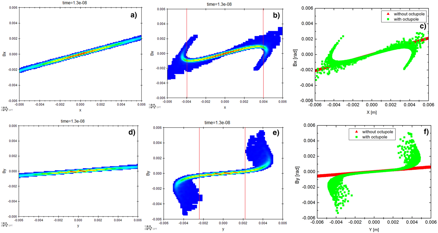
Fig. 11. Phase space distribution of the beam at the target position (object plane) without octupole (a) (d) and with octupole (b) (e), and comparison of the phase space distribution with and without octupole (c) overlapping of (a) and (b) with the same scale, (f) overlapping of (d) and (e) with the same scale. (a, b, c) for the x plane phase space and (d, e, f) for the y plane.
Another way to obtain good uniform beam distribution at the target with octupoles is to use a collimator at the starting point of the beam matching line for truncating the Gaussian distribution beam into parabolic distribution, as shown in Yuri et al. (Reference Yuri, Ishizaka, Yuyama, Shibori, Okumura and Yoshida2011). With the beam transport settings described above, a collimator with the radius of 1.5 mm and length of 1 cm has been placed at the initial beam position to obtain a parabolic beam while a uniform beam distribution at the target is obtained by tuning two octupoles individually. The simulation results are shown in Figure 12, where (a) is the x–y plane uniform distribution described by (c) and (d) in x and y planes separately and (b) is the x plane phase space (black) compared with the original one (colored, without octupoles and collimator). The results demonstrate that using the collimator, renders perfect uniform beam and the phase space is affected very little compared with the original one. Another advantage of this method is that the collimator is far away from the target, therefore the secondary particles from electron interaction with the collimator have no effect on the imaging compared with the collimator close to the target case.
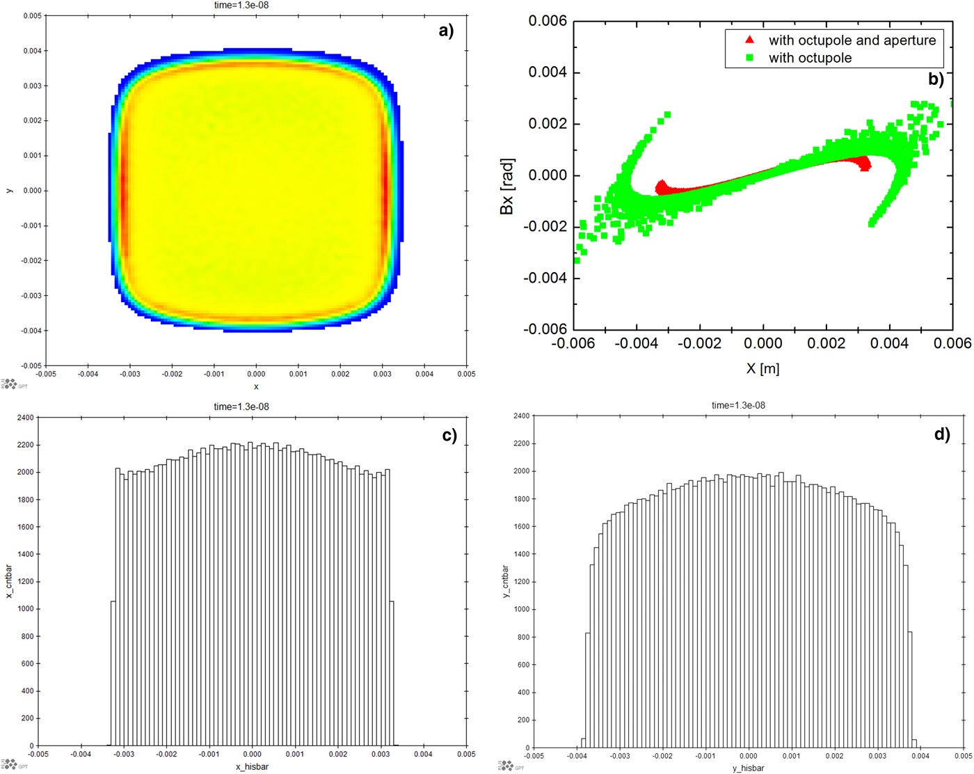
Fig. 12. The beam distribution at the target with initial collimated parabolic distribution beam, (a) x–y plane, (b) x plane phase space, red is with octupoles and green is without octupoles, (c) x and (d) y plane uniform distribution of (a).
The initial beam transverse distribution is assumed to be Gaussian in the simulations, which is the general case for the LINAC photoinjector. There are other means to change the initial beam to be smoothly Gaussian or a transversely parabolic distribution by thin foil scattering as shown in Yuri et al. (Reference Yuri, Ishizaka, Yuyama, Shibori, Okumura and Yoshida2011). Therefore this assumption is valid for practical experimental studies. From the above analysis, the octupoles have a negligible effect on the center part of the beam angle-position correlation. In practice, it is therefore very easy to achieve matching beam conditions with the uniform beam. First, the beam size must be large at the target and have matched angle-position correlation. Then the two octupoles must be placed at the flat beam positions as shown in Figure 9 to produce the uniform beam at each plane by tuning each octupole. This process renders the desired transverse distribution beam at the target for imaging.
The HEER principle is based on the beam passing through the target being imaged point to point on the image plane. The beam transverse distribution at the target will affect the image contrast significantly. The beam at the high-aerial density part will be scattered more and electrons with a large scattering angle will be filtered out by an aperture at the Fourier plane. Therefore, from theory analysis with uniform beam the low intensity image corresponds to the high-aerial density target. Firstly, by adding octupoles a uniform distribution illuminating beam can be generated; secondly, with an aperture the center part beam angle position correlation is barely affected by octupoles, therefore the spatial resolution does not degrade. With a uniform beam distribution, one can obtain target aerial density distribution information with single shot imaging even though the beam is not stable, which is also critical to the three-dimensional HEER (Zhao et al., Reference Zhao, Cao, Shen, Wang, Zong, Xiao, Zhu, Zhou, Liu, Cheng, Zhao, Zhang and Gai2017).
Summary and conclusions
Beam transverse uniform distribution requirements from experiments are studied. Strips with different materials but the same thickness and the same areal-target density have been imaged and analyzed respectively with 46 MeV beams. Although there are some discrepancies between the experimental result analyses and theory, the results prove that the areal-density distribution can be attained using HEER. The reason for this discrepancy is being investigated and shows the importance of the beam transverse uniform distribution for illuminating the target. The areal-density resolution is critical for these diagnostics, which is determined by the image intensity information. In addition, the method for generating the transverse uniform distribution beam with octupole magnets was studied and demonstrated by simulations, which is relevant for diagnostics with image contrast information. The method used in simulations can be a guide for experimental design and operations. Simulation results also confirm that the octupole will not affect the center part beam angle-position correlation required by the imaging lens. Therefore, a collimator near the target or at the initial beam position can be used for filtering out the beam edge to obtain more uniform beam and to prevent changes in the phase space requirements in the practical experiment. This method is useful and easily implemented in experiment. Two octupoles will be added into the HEER beam matching line and more experimental results will show in future HEER experimental studies for areal-density diagnostics.
Acknowledgements
The work is supported by the National Natural Science Foundation of China (11435015 and 11505251), the Ministry of Science and Technology of China (2016YFE0104900) and the Chinese Academy of Sciences (28Y740010). One of the authors Q. Zhao would like to thank Dr. Hernandez-Garcia Carlos (Jefferson Lab) for proof reading and editing the manuscript.