1. INTRODUCTION
High current electron beams with large cross-section of about 103–104 cm2, at the electron energy of 500–600 keV, and current of 104–106 A are used for excitation of high-power gas lasers and for solution of technological problems.
The main factor limiting the electron beam current is the self-magnetic field of the beam that curves the electron trajectories and thus increases the energy loss at a support structure and in the anode foil when the beam is transported into the gas-filled chamber.
A well-known method to decrease the influence of the self-magnetic field on the beam formation is the overlaying of the external magnetic field in the region of the diode and the laser cell (Sethian et al., Reference Sethian, Pawley, Obenschain, Gerber, Serlin, Sullivan, Lehecka, Webster, Smith, Corcoran, Altes, Baker and Cooperstein1995; Reference Sethian, Hegeler, Myers, Friedman, Obenschain, Lehmberg, Giuliani, Kepple, Swanekamp, Smith, Weidenheimer, Morton, Schlitt, Smilgys, Searles, Reinovsky and Newton2001). This method is used in high-power electron beam accelerators with pulse forming lines. The disadvantage of the method is a bilateral injection resulting in the current density increase on the foil. Additionally, the use of the pulse forming lines complicates the design of electron beam accelerator.
Another possibility to decrease the influence of the magnetic field is the diode sectionalization (Angood et al., Reference Angood, Bailly-Salins, Hirst, Kidd and Shaw1992; Kidd et al., Reference Kidd, Angood, Bailly-Salins, Carr, Hirst, Shaw, Prestwich and Baker1993; Kovalchuk et al., Reference Kovalchuk, Abdullin, Grishin, Gubanov, Zorin, Kim, Kumpjak, Morozov, Skakun, Stepchenko, Tarasenko, Tolkachev, Schanin and Tsoy2003). In this approach, a vacuum diode is divided by means of magnetically shielding plane-shaped current returns into a number of magnetically shielded diodes with acceptable value of magnetic field. A guiding magnetic field is absent in this type of the designs. In contrast to the previous version, the beam entrance into the laser cell can be multilateral (by number of the sides of cell) that allows decreasing the beam current density and, consequently, the thermal load on the foil. The disadvantage of this method is increase of the diode sizes due to the necessity to provide the insulation gaps between the cathodes and magnetically shielding planes as well as complication of the accelerator design.
Kidd et al. (Reference Kidd, Angood, Bailly-Salins, Carr, Hirst, Shaw, Prestwich and Baker1993) have shown as well that magnetic field in the diode can be decreased using the so-called mid-plane current returns. The planes are installed in magnetically shielded diodes into the gaps between the halves of the cathode connecting the ribs of the gas chamber with the walls of the vacuum chamber where it is possible. The installation of the planes results in dividing each of the magnetically shielded diodes into two and corresponding decreasing of the magnetic field, the electrical contact being kept between the halves of the cathode. The mid-plane current returns as well as magnetically shielding planes complicate the diode design and enlarge its dimensions due to the isolation gaps between the large-area electrodes (cathodes and planes).
Magnetic field in the diode can be, obviously, decreased when current returns in the shape of small-diameter rods are used. These rods can be installed normally at the inner surface of the vacuum chamber connecting, e.g., the wall of the vacuum chamber with gas chamber ribs thus shielding partially the diode periphery regions from magnetic field of the current flowing in the central part. In contrast to the sectionalization, this method requires no cathode division because the rod current returns can be installed in the holes with relatively small diameter made in the non-emitting parts of the cathode opposite the gas chamber ribs. Installation of the rod current returns results in no significant complication of the diode design and no increase of its sizes.
Previously (Abdullin & Morozov, Reference Abdullin and Morozov2013), the calculation and simulation of magnetic fields in a high-power vacuum diode of the accelerator for gas medium pumping (Kharlov et al., Reference Kharlov, Kovalchuk, Volkov, Zherlitsyn, Bastrikov, Zorin, Kiselev, Smorudov, Tsoy, Kovalchuk and Remnev2010) were made. It was revealed that magnetic field at the diode edges are sufficiently high (about 500 G) and may cause the energy loss at the electron beam transition into gas.
To decrease the magnetic field, the rod current returns were suggested to be used and the number, and location of the rods providing a substantial (more than two times) decrease of the magnetic field at the vacuum diode periphery have been found out.
In this paper, the experimental verification of the results of the latter investigation is carried out. The electron beam parameters are recorded when the rod current returns are placed in the vacuum diode of the accelerator (Kharlov et al., Reference Kharlov, Kovalchuk, Volkov, Zherlitsyn, Bastrikov, Zorin, Kiselev, Smorudov, Tsoy, Kovalchuk and Remnev2010), and the inter-electrode distance, shape, and dimensions of the emitting parts of the cathodes are corrected corresponding to the magnetic field reduction.
2. EXPERIMENTAL TECHNIQUE
Figure 1 illustrates the vacuum diode scheme. The vacuum diode is developed for obtaining a radially convergent electron beam. The vacuum diode is assembled in the cylindrical vacuum chamber 1 and formed by two magnetically shielded diodes, each of them powered by an individual generator. The cathodes 2 of the vacuum diode are made of the stainless steel sheets in the shape of the lateral surface of a cylinder. The cathode edges are framed with a tube to be protected from breakdowns. The current leads are the central electrodes of vacuum coaxials 3. Each cathode contains three emitting units 4 placed opposite the output windows 5 along the axis of the gas chamber 6 which is the anode. In the original version of the diode (Kharlov et al., Reference Kharlov, Kovalchuk, Volkov, Zherlitsyn, Bastrikov, Zorin, Kiselev, Smorudov, Tsoy, Kovalchuk and Remnev2010), the emitting units were the rectangular regions of the cathode with dimensions of 160 × 1100 mm and a 2-mm-length dielectric fiber-flock glued to a metal base normally to the surface. The distance from the ends of the fibers to the ribs of the support structure of the output windows was 50–55 mm.
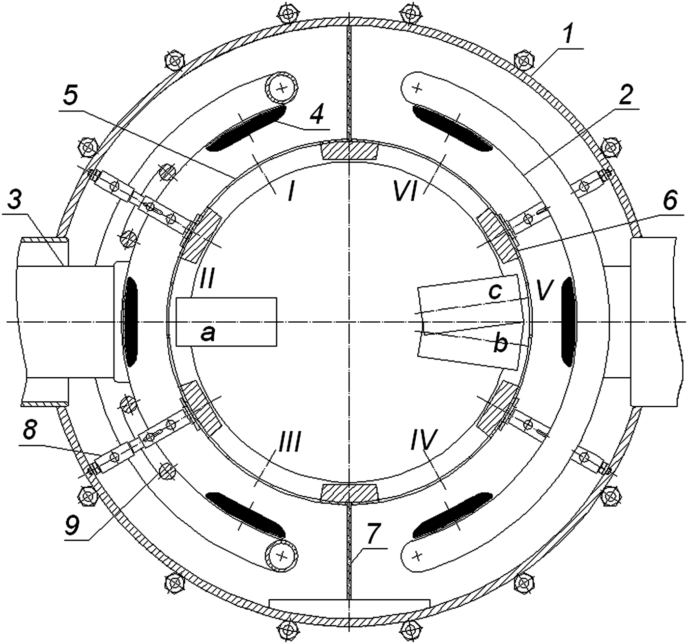
Fig. 1. Scheme of the diode. (1) vacuum chamber, (2) cathode, (3) current lead, (4) emitting unit, (5) output window, (6) gas chamber, (7) magnetically shielding plane, (8) rod current return, (9) protective screen. I–VI—positions of output windows, a, b, and с—positions of the line-up of calorimeters.
Reducing of the magnetic field in the diode with the rod current returns allows decreasing the loss of electron energy in the foil, thereby it becomes possible to increase the current density in the diode and, correspondingly, the density and value of output energy of the beam beyond the foil. For this purpose, as well as for matching of the beam sizes to the output windows ones, the flock-based emitting parts were removed in the modified diode, the design of the emitting parts was changed, namely, their width and length were reduced and the length of the cathode-anode inter-electrode gaps was reduced as well. Shortening of the inter-electrode gap at the same current value, evidently, promotes to decrease the magnetic field influence on the electron beam forming as well. The convex-shaped modified emitting units 4 have the bases made of graphite-fiber fabric with a plywood structure and are covered with velvet that provides the high emission properties of the cathode and reduces a possibility of breakdowns. Figure 2 presents the appearance of the modified emitting units. The width of the emitting unit is 110 mm, the length is 900 mm, and the sharp edges of the emitting units are rounded. The cathode-anode inter-electrode distance is 34–36 mm.
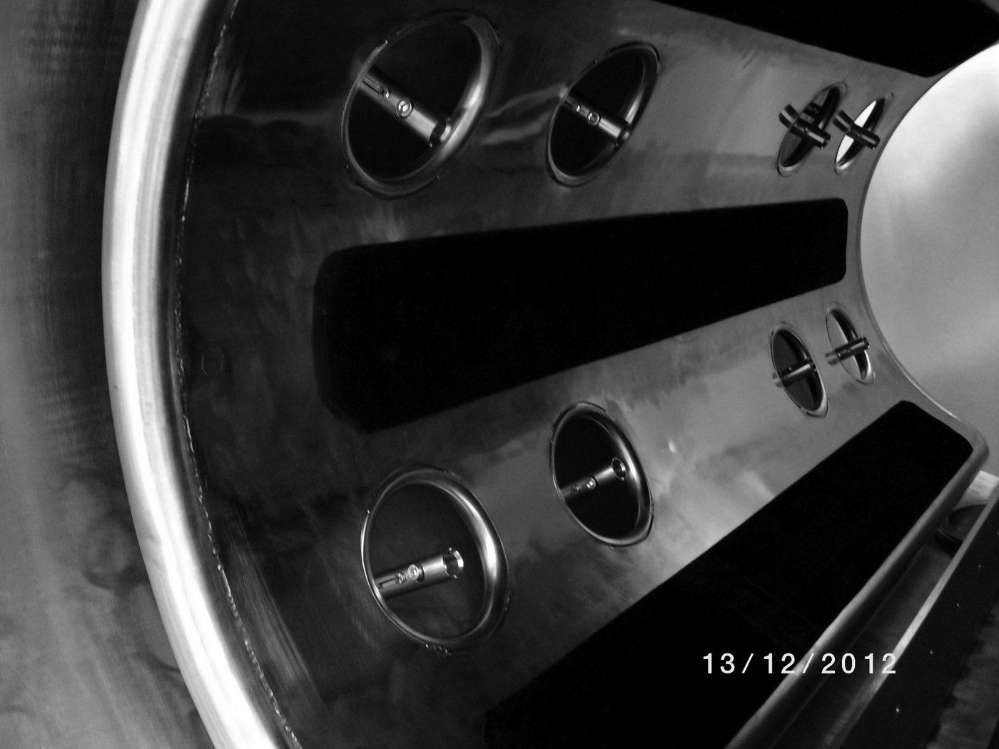
Fig. 2. The external view of the rod current returns and modified emitting units of the cathodes.
The output windows are closed with a 40-µm thickness titanium foil. The height and the width of the ribs of the support structure of the output windows is 3 mm. In Figure 1, the output windows are numbered with Roman numerals I–VI. To match the electron trajectories at the beam periphery with the position of the output windows I, III, IV, and VI, the correspondent emitting units in the modified diode were shifted relative to the position opposite the windows to the cathode edges approximately by 2° along the cathode surface.
The gas chamber was mounted coaxially with the vacuum chamber by means of two magnetically shielding planes 7.
The rod current returns were 16 split sliding contacts made in the form of 20-mm-diameter stainless steel rods 8 (Fig. 1). The rods were installed normally at the inner surface of the vacuum chamber in four rows opposite the ribs of the gas chamber and were connected with the ribs (see Figs. 2, 3 as well). The rods were placed in the holes made in the cathodes symmetrically relative to the symmetry plane which was perpendicular to the gas chamber axis. The distances from the plane of symmetry to the rod axis were 225 mm and 425 mm. To increase the electric strength of the insulation gaps between the cathodes and rods, the edges of the holes were closed with metal screens in the shape of a torus 9 with the inner diameter of 100 mm.
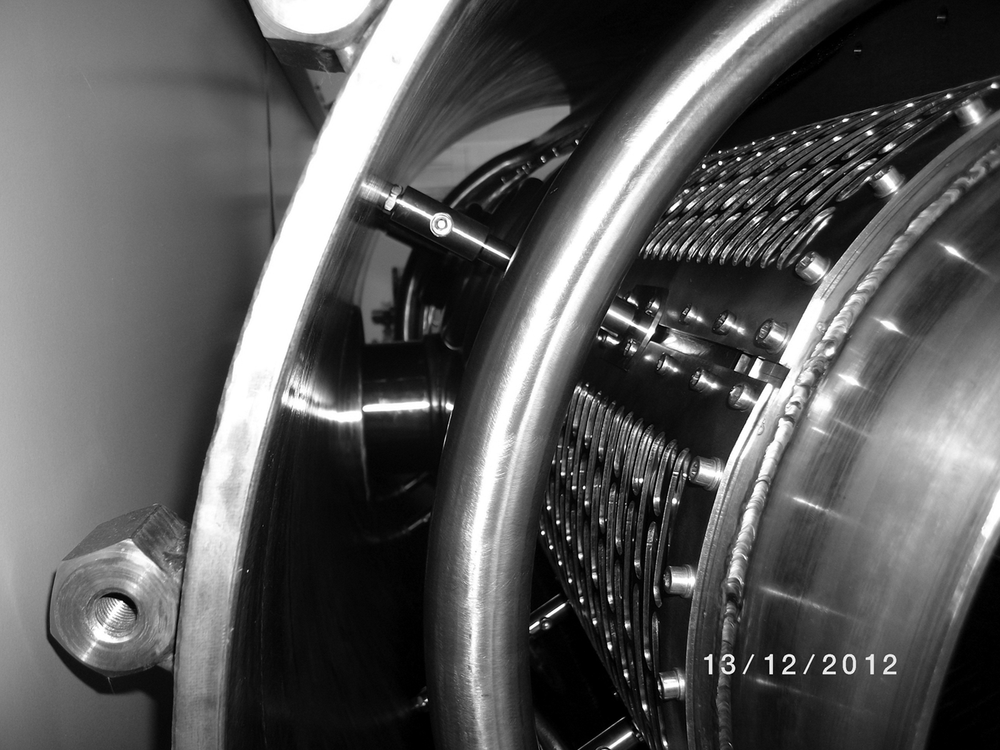
Fig. 3. The rod current returns in assembly.
Diagnostic facilities available at the setup (Kharlov et al., Reference Kharlov, Kovalchuk, Volkov, Zherlitsyn, Bastrikov, Zorin, Kiselev, Smorudov, Tsoy, Kovalchuk and Remnev2010) allowed obtaining the data on the voltage, current, and electron beam energy in the magnetically shielded diodes as well as on energy and structure of the electron beam transmitted outside the foil. The diode voltage was measured with resistive dividers; the current values were determined by the data of inductive probes; the power and energy of the electron beam versus time were calculated from the obtained waveforms of voltage and current. The energy of the beam passed through the foil was evaluated by the readings of 18 TPI-2M calorimeters with the receiving surface area of 6 × 6 cm2 assembled into the line-up. The total area of the receiving surface of the calorimeters were thus equal to 6 × 108 cm2, the outputs of the calorimeters were connected in series. The line-up was installed in the gas chamber in three positions. In the position a, the receiving surface of the calorimeters was placed opposite the symmetry axis of the windows at a 0.5-cm distance from the foil surface. In the positions b and с, the line-up was turned relative to the gas chamber axis so that the receiving surface of the calorimeters shifted relative to its initial position by 3 cm in a clockwise or counter-clockwise. Summation of readings in two latter cases resulted thus in obtaining the estimation of energy of the beam injected into the gas chamber through the central part of each of the I-st – VI-th output windows with an area equal to 12 × 108 cm2. Side flanges at the gas chamber were missing under calorimetric measurements. The charging voltage of the generators was 90–95 kV.
The data on the size and structure of the beam were obtained by means of the beam autograph on the radiachromic films. The films were installed in the output windows from the gas chamber side closely to the foil.
3. EXPERIMENTAL RESULTS
Experiments showed that the voltage and current waveforms as well as dependences of the electron beam power and energy on time when using rod current returns (Fig. 4) are close to the ones obtained in the initial variant of the diode (Kharlov et al., Reference Kharlov, Kovalchuk, Volkov, Zherlitsyn, Bastrikov, Zorin, Kiselev, Smorudov, Tsoy, Kovalchuk and Remnev2010). At the voltage waveforms there is no spike at the pulse start what indicates the satisfactory operation of the cathode. At the charging voltage of 95 kV, the voltages at the magnetically shielded diodes are 540–550 kV; the total diode current reaches 240 kA; the duration of the voltage pulse at the base is 340 ns; the energy transferred from the generator to the diode during the voltage pulse is 19 kJ.

Fig. 4. Waveforms of the voltage U and total current I of the electron beam diode as well as of the power P and energy of the electron beam W in the diode versus time. For convenience, the dependences P(t) and W(t) are presented in returned polarity. The charging voltage of the generators U 0 = 95 kV.
Figure 5 shows the photos of the electron beam prints on the radiachromic films. The prints were obtained by the film irradiation of the beams withdrawn from the emitting units located in the center and at the edge of the cathode. Electron beams have the width of 130–140 mm at the anode and enter the output windows completely. The shadows from the support structure resulting from the oblique incidence of electrons to the foil surface are practically missing at the prints. The input of the electrons into the foil is realized under small angles what is the consequence of magnetic field smallness in the diode and decrease of the inter-electrode gap.
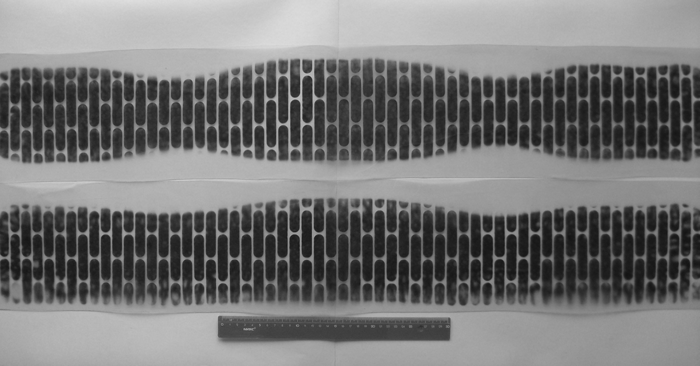
Fig. 5. Autographs of the beam on the radiachromic films installed behind the II-nd (upper) and III-rd (lower) output windows.
At the shadow length less than 0.5–0.75 mm and height of a support structure rib of 3 mm, the entry angles measured from the normal to the foil surface are not larger than 14°. These are rather small angles ensuring the electron beam passage through the foil with minimum loss.
The magnetic field value in the diode can be estimated from the relations:
Here, α is the angle of electron entry into the foil; d is the length of inter-electrode gap; r L, q, and m are the Larmor radius, charge and rest mass of electron, respectively; c is the light velocity; γ is the relativistic factor; B is the induction. When α = 14°, d = 36 mm, and electron energy is 500 keV, we will find that r L = 15 cm and B = 194 G which corresponds to the results (Abdullin & Morozov, Reference Abdullin and Morozov2013).
Decrease of the inter-electrode gap makes sufficient contribution in reducing of the angles of electron entrance into the foil. From (1) and (2) we will find that shortening of the inter-electrode gap from 50 to 36 mm at the 523-Gs magnetic field (Abdullin & Morozov, Reference Abdullin and Morozov2013) at the beam edge without rod current returns in the diode can result in decrease of the angles of electron entrance into the foil from 64° to 40°. At the same time, in accordance with (1) and (2), magnetic field reducing from 523 to 194 Gs when using the rod current returns at invariable length of the inter-electrode gap (50 mm), decreases the entrance angles to 20°.
The feature of the obtained prints is the availability of the beam compression regions in the space between the adjacent rods installed at a 225-mm distance from the plane of symmetry of the gas chamber resulting in the uneven distribution of the beam current along the gas chamber at the edges of the output windows. Minimal width of the beam in the compression region is about 100 mm. The reason of compression is a trajectory curvature of electrons emitted from edges of the emitting surfaces near the rods under the influence of a strong magnetic field of return currents. However, increase of length of the shadows from the support structure in the compression regions was not observed. The absence of significant shadows from the support structure in the compression regions indicates that the beam compression under the influence of magnetic fields of the rod currents is not accompanied by essential loss of the beam energy. Due to the essential magnetic fields, breakdown formation of the insulation gaps between the cathodes and the rods takes no place. When disassembling the diode after ~300 accelerator operations, the breakdown traces on the electrodes were not found.
Availability of non-uniformity of the beam current distribution along the gas chamber axis at the edges of the output windows related to the influence of the rod fields can be considered, however, as a disadvantage resulting in the non-uniform excitation of gas. Under conditions of the present work there was no task to obtain a high uniformity at the edges of the windows. It was important to increase the electron beam energy injected into gas and to obtain of a beam with a high current density in the central part of the windows. If necessary, the influence of magnetic fields of the currents of rod current returns can be reduced by removing the rods to the diode periphery. One can see from the prints obtained that the current returns placed at 425-mm distance from the central plane of symmetry of the gas chamber have a little influence on the beam width. Another way to reduce current fields of the rod current returns may be shortening of the gap between the back side of the cathode and the wall of the vacuum chamber (Abdullin & Morozov, Reference Abdullin and Morozov2013). In this case, the field decrease is achieved by reducing the currents induced in the closed contours formed by the current returns at the change of magnetic fluxes related to the currents of current leads.
Figure 6 presents the results of the calorimetric measurements. The graphs presented here indicate the values of the energy recorded in each of the three positions of the calorimeters a, b, and c for each of the output windows.
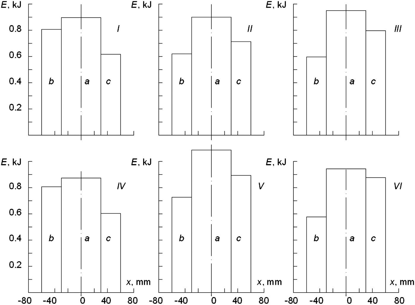
Fig. 6. Values of the electron beam energy recorded by the line-up of calorimeters located in the positions a, b and c opposite the I-st – VI-th output windows. The charging voltage of the generators U 0 = 95 kV.
The energy of the electron beams transported into the gas chamber through all output windows is high enough. The energy recorded by the calorimeters in the position a and entering through the central parts of the I-st–VI-th windows is 5.64 kJ. The total energy recorded by the calorimeters in the positions b and c is 8.62 kJ. Taking into account that the beam cross section exceeds the total area of the receiving surface of the calorimeters in positions b and c, the total energy injected into the gas chamber can be estimated at the level of 9.5 kJ. At the average electron beam energy of 19 kJ obtained in the diode during the time of the cathode voltage drop to zero, the coefficient of the energy transfer from the diode into the gas chamber is equal to 0.5 which is close to results of works when the sectionalized diodes with magnetically shielding planes were used (Kidd et al., Reference Kidd, Angood, Bailly-Salins, Carr, Hirst, Shaw, Prestwich and Baker1993; Kovalchuk et al., Reference Kovalchuk, Abdullin, Grishin, Gubanov, Zorin, Kim, Kumpjak, Morozov, Skakun, Stepchenko, Tarasenko, Tolkachev, Schanin and Tsoy2003). In accordance with (Alexeev et al., Reference Alexeev, Ivanov, Kovalchuk, Losev, Mesyats, Mikheev, Panchenko, Puchikin, Ratakhin, Yastremsky, Kovalchuk and Remnev2010; Reference Alexeev, Aristov, Ivanov, Kovalchuk, Losev, Mesyats, Mikheev, Panchenko and Ratakhin2013), maximum energy transported into gas in the initial version of the vacuum diode with the flock-covered cathodes and in the absence of the rod current returns was 6.5–7.5 kJ at the beam energy in the diode of 20 kJ. The coefficient of the energy transfer from the diode into the gas chamber is thus no higher than 38%. Application of rod current returns in common with inter-electrode gap shortening allows increasing the efficiency of the energy transfer from the diode into the gas as well as the value of energy of the electron beam transported into the gas by no less than 1.3 times.
4. CONCLUSIONS
Thus, the experimental studies of the wide aperture vacuum diode aimed at increase of energy of the electron beam transported out of the diode into the gas were carried out. Increase of the energy transfer efficiency is obtained resulting from the rod current returns setting and correction of the inter-electrode distance, the shape, and the dimensions of the cathode emitting parts in the vacuum diode. It is shown that this design of the vacuum diode allows essentially (more than two times) decreasing the magnetic field value and electron beam energy loss in the foil. The installation of the rod current returns results in no dysfunction of the diode operation mode; no breakdowns of the cathode-anode (gas chamber) gaps and cathode-rod current return ones are recorded. The energy of the electron beam passed through the foil was increased by up to 1.3 times. In whole, a possibility to use the rod current returns for decreasing magnetic fields and increasing the energy of the electron beam transmitted into gas in high-power diodes was confirmed experimentally.
ACKNOWLEDGMENTS
The work was supported by RFBR (Grant Nos. 10-08-00022, 13-08-00068), programs “Problems of Physical Electronics, Charged Particle Beams, and Generation of Electromagnetic Radiation in High-Power Systems,” “Extreme Light Fields and Their Applications” of fundamental investigations of Presidium of RAS, and SB RAS Grant No.6.


