


1. INTRODUCTION
Intense particle beams, including high-power pulsed laser, ion, and electron beams offer the possibility of surface modification of components based on extreme thermal and mechanical loads to produce non-equilibrium microstructures and compound phases with fine grains in the surface layers otherwise unobtainable by traditional processing methods, especially for some hard-to-be manufactured alloys with improved wear, corrosion, and fatigue performance, etc. (Davis et al., Reference Davis, Remnev, Stinnett and Yatsui1996; Renk et al., Reference Renk, Sridharan, Harrington, Johnson and Lahoda2010; Zhu et al., Reference Zhu, Zhang, Tang and Lei2011; Chernov et al., Reference Chernov, Berezneeva, Beloglazova, Ivanova, Kireeva, Lider, Remnev, Pushilina and Cherdantsev2014; Lei, et al., Reference Lei, Zhu and Guo2016). Particularly, high-intensity pulsed ion beams (HIPIB) developed in last two decades, possess some unique advantages over laser and electron beams, such as energy deposition of the highest efficiency up to 100% without beam reflection on treated surfaces frequently encountered for laser and electron beams, as well as higher specific energy density per unit volume due to the deposited energy concentrating in a thin surface layer within a few micrometers tailorable by the ion kinetic energy and ion species (Bystritski & Didenko, Reference Bystritski and Didenko1989; Rej et al., Reference Rej, Davis, Olson, Remnev, Zakoutaev, Ryzhkov, Struts, Isakov, Shulov, Nochevnaya, Stinnett, Neau, Yatsui and Jiang1997; Renk et al., Reference Renk, Provencio, Prasad, Shlapakovski, Petrov, Yatsui, Jiang and Suematsu2004; Remnev et al., Reference Remnev, Uglov, Shymanski, Pavlov and Kuleshov2014). Due to the high efficiency of ion beam–matter interaction, significant coupled thermal and mechanical loads could be obtained under HIPIB irradiation at a beam power/energy density output per pulse of 1–2 order lower than that of laser and electron beams. Typical HIPIB parameters for surface modification of components are in the range of energy density 1–10 J/cm2 under ion accelerating voltage of 100–400 kV in pulse duration typically of 10 ns–1 µs, causing intense heating and cooling at a rate of higher than 109 K/s in the near-surface layers of 0.1–10 µm of irradiated materials. For instance, ion beam shock processing is thus obtainable in a non-confinement regime at a moderate power density of 107–108 W/cm2, resulting in surface hardening/strengthening down to a subsurface layer of hundreds micrometers for metallic and ceramic components under the HIPIB irradiation (Lei et al., Reference Lei, Zhu, Liu, Xin, Han, Li, Dong, Wang and Miao2009; Zhu et al., Reference Zhu, Zhang, Song and Lei2014). In addition, HIPIB output at a higher power/energy density is applicable for high-rate deposition of functional thin films by ablation of solid targets at room temperature (Suematsu et al., Reference Suematsu, Kitajima, Suzuki, Jiang, Yatsui, Kurashima and Bando2002; Zhu et al., Reference Zhu, Suematsu, Jiang and Yatsui2008). Therefore, the HIPIB technology for surface modification relies on microstructures and/or compounds far from equilibrium states due to strongly coupled thermal and dynamic effects under the beam–material interactions, greatly distinguished from conventional ion implantation technique mainly based on alloying and doping effects.
Magnetically insulated ion diodes (MIDs) have been intensively investigated since the last three decades and are still recognized as the most efficient type of high-power ion source for high-intensity pulsed ion beam generation (Bystritski & Didenko, Reference Bystritski and Didenko1989; Rej et al., Reference Rej, Bartsch, Davis, Faehl, Greenly and Waganaar1993; Werner et al., Reference Werner, Piekoszewski and Szymczyk2001; Zhu et al., Reference Zhu, Lei and Ma2002). Note that, for HIPIB practical applications, it is necessary to provide high reproducibility of its parameters on the irradiated targets. Stability of HIPIB parameters in a series of repetitive pulses is involved with not only the amplitude and shape of accelerating voltage pulse from pulsed power sources applied to ion diodes, but also the ion beam energy distribution along axis and cross-section direction upon ion beam transportation and propagation in vacuum. It is well known that, conventional ion implanter with ion current up to mA range is commonly operated under a low background pressure of 1 mPa order with long mean free path for ion transportation to achieve high-current implantation of reproducible parameters for surface modification of materials (Lei et al., Reference Lei, Zhu and Wang2002). The HIPIB source of ion diodes is also intrinsically vacuum-based system, nevertheless, it could be extended to a wider application if it is robust and tolerant under low or medium vacuum conditions of the background gaseous pressures due to variations in processing conditions such as degradation of ion source material itself, gaseous release from either ion source material or processed components, or introducing reactive gases puff into the processing chamber during HIPIB irradiation for materials processing. Thanks to the short pulse high-current discharge process of HIPIB generation as well as its unique modification principle of high-energy density ion–matter interaction other than that of alloying element incorporation highlighted in conventional ion implantation, it is feasible for the HIPIB technology to utilize discharge and transport at a higher background pressure. It was reported in some previous studies that a large flux of energetic neutrals in the ion beam may be produced by MIDs (Pointon Reference Pointon1989; Pushkarev et al., Reference Pushkarev, Isakova and Khailov2015). The neutrals are generated through charge exchange processes between the ions and background gas molecules in anode–cathode (A–K) gap. The charge exchange in an ion diode is actually beneficial to overcoming the limitation of space-charge effects in the A–K gap for intense ion beam extraction. And the energetic neutrals of the complex beam also contribute significantly to enhancement in the HIPIB energy density. As a result, the energy density per shot could be enhanced by a factor of 25–30 as compared with the space-charge-limited value (one-dimensional Childe–Langmuir limit) (Pushkarev et al., Reference Pushkarev, Isakova and Khailov2015). Moreover, the standard deviation of HIPIB energy density in a series of pulses does not exceed 11%, whereas the corresponding variation of ion current density was 20–30% (Pushkarev et al., Reference Pushkarev, Isakova and Khailov2014). The improved stability of energy density from pulse to pulse is thought to be associated with the generated energetic neutrals from the charge exchange between accelerated ions and background gas molecules.
However, it was reported that the volt–ampere characteristics of ion diode and ion beam energy did not depend on the background pressure within the range of 2.6–1300 mPa (Stepanov et al., Reference Stepanov, Lopatin, Remnev and Melnikova2008), where an annular MID with a dielectric anode in a B r magnetic field was operated at diode voltage of 400 kV and pulse duration of 60 ns. It was also found that, the pressure in the vacuum chamber increased at the expense of decomposition and/or decontamination of the dielectric material on anode surface, and the amplitude of pressure increase varied within a range 27–133 mPa during a series of repetitive pulses. The pressure within А–K gap is estimated to be up to 100 Pa during a pulse, taking into account the volume of diode chamber of 0.25 m3, the effective anode surface area of 200 cm2 and the А–K gap distance of 1 cm. Therefore, in that case, the background pressure in diode chamber between pulses up to 1300 mPa could have a negligible influence on operating mode of the ion diode. Nevertheless, some unfavorable phenomenon, for example, breakdown of coils powered with pulsed voltage of 5–10 kV for generating a magnetic field or surface flashover in chamber wall, occurred more frequently as the chamber pressure increased, causing unstable operation of the diode system. On the other hand, change of background pressure in diode chamber also affects HIPIB transportation to a target. The ion beam transportation process was studied previously for ion diodes of different types (Olson Reference Olson1982), and it was shown that MIDs have a maximal HIPIB divergence of 1°–4° (ratio of HIPIB spot radius at half-height to the distance from the diode), unobtainable in reflex diodes and pinch diodes. When an ion beam is injected into neutral gas, the gas will be ionized and stripped to some equilibrium charges, and a portion of the ions in the HIPIB will lose their kinetic energy due to induced electric fields and inelastic collisions, creating a plasma distribution that facilitates neutralization of the ion beam. In the self-pinched mode, the ion beam ionizes the gas and creates a highly conductive plasma channel during the initial period of the beam pulse. Self-pinched transport of intense ion beams in low-pressure background gases was also studied for ion-driven inertial confinement fusion using numerical simulations, where the self-pinched transport of intense proton beams of MeV range produced on Gamble II (1.5 MeV, 100 kA, 3 cm radius) is expected to occur at gas pressures 4–10 Pa of He or 0.4–1.3 Pa of Ar (Rose et al., Reference Rose, Ottinger, Welch, Oliver and Olson1999).
Despite many researches were carried out to study influence of background gases pressure in diode chamber on HIPIB generation and transportation, there are no experimental investigations on MIDs with self-magnetic insulation. Especially, it is still not practical to define optimum pressure of residual gases in diode chamber of HIPIB equipment for surface engineering applications where the moderate kinetic energy of ions is preferably in hundreds keV for more effective depositing of the beam energy in the top surface layer of processed components. In recent studies, stability of HIPIB generation in a series of pulses for strip ion diodes of self-magnetic insulation mode are presented at a low pressure in diode chamber about 10 mPa (Pushkarev et al., Reference Pushkarev, Isakova and Khailov2014). In this study, influence of background pressures varied in the two order of magnitude of 1–100 mPa on ion beam characteristics is comparatively studied for self-magnetic field MID with graphite anode on two HIPIB sources differed in vacuum system, toward a general understanding of stability of HIPIB parameters at varying background pressures for HIPIB technological equipment development.
2. EXPERIMENTAL
2.1. HIPIB equipment
HIPIB generation from MIDs with self-magnetic insulation were carried out on two ion accelerators, TEMP-6 (Zhu et al., Reference Zhu, Lei and Ma2002) and TEMP-4M (Pushkarev et al., Reference Pushkarev, Isakova and Khailov2013), having similar pulsed power design of a microsecond pulsed voltage generator (Marx generator) and a nanosecond pulsed voltage generator (double coaxial pulse forming line, PFL). During operation, the PFL is charged by Marx generator, and then a bipolar pulse is output from the PFL through impedance-matched transmission line to the MIDs, where the first negative pulse with peak voltage of 150–200 kV lasting 480–500 ns for explosive emission plasma formation and the second positive one of 200–250 kV with pulse duration of 120 ns for HIPIB extraction. In order to enhance electrical efficiency, the charging inductor in previous PFL design (Zhu et al., Reference Zhu, Lei and Ma2002) has been removed to eliminate current leakage through it. As a result, the energy delivery from the PFL to the diode is increased by a factor of 1.5 that in turn stabilizes to some extent the anode plasma formation process. Moreover, to improve the statistical stability of PFL output for the bipolar pulse with an accurate delay time, the PFL gas switches previously operated in self-breakdown of N2 and SF6 mixtures at a pressure range within 1.5–3.0 atm (Zhu et al., Reference Zhu, Lei and Ma2002) have been modified with a passive external triggering circuit connecting from the output switch to the reverse switch (the main spark gap) of PFL, by which the reverse switch is externally started by a triggering pulse transformed from a voltage divider near the output switch during output of rising front of the first negative pulse., the delay time of bipolar pulse, that is, duration of the first negative pulse in the present case, can be precisely controlled with a jitter no more than ±10 ns predefined by the length of coaxial cable in the passive triggering circuit connecting the two PFL switches. In this newly upgraded PFL setup, the gas switches can be filled with pure N2 at a higher pressure up to 6 atm, and an optimal delay time of 480–500 ns is determined for the present study.
2.2. Characterization of accelerator and HIPIB parameters
The diode voltage was measured with a voltage divider installed on the impedance-matched transmission line between the PFL output switch and the diode unit, and the diode current was measured using a Rogowski coil just behind the transmission line. Electrical signals from the sensors were recorded with a Tektronix DPO 2024B oscilloscope (200 MHz, 1 × 10⁹ sampling/s). The diode units and typical waveforms of diode voltage and current are presented in Figure 1. The anode is made from graphite having a focusing curvature of 15 cm.
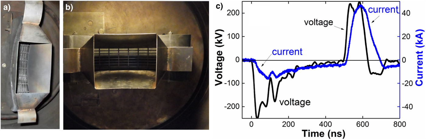
Fig. 1. Ion diodes of self-magnetic field insulation in two accelerators and typical waveforms of accelerating voltage and total diode current: (a) MID in TEMP-4M, (b) MID in TEMP-6, (c) waveforms of voltage and current.
HIPIB total energy and energy density distribution in cross-section were measured by employing an infrared (IR) diagnostic method (Pushkarev et al., Reference Pushkarev, Isakova and Khailov2015). This method enables the beam energy measurement of high spatial resolution (1 mm) and high sensitivity (0.01–0.02 J/cm2). A typical thermal imprint recorded by the IR camera 100 ms after one pulse irradiation onto a stainless steel target (thickness of 0.1 mm) is illustrated in Figure 2, together with energy density distribution along the ion beam cross-section vertical and horizontal lines indicated in the thermal imprint. The thermal imprint of the beam was recorded through a barium fluoride (BаF2) window, located on the flange of the diode chamber. This method was calibrated before measurement since the BaF2 window has incomplete transmission in spectral range of 7–14 µm for the IR camera used in this study.
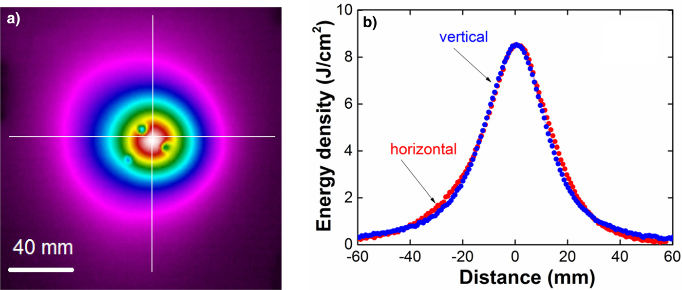
Fig. 2. Infrared (IR) diagnostic method: (a) typical IR image of the ion beam spot imprint on a thin foil metal target, (b) the beam energy density distribution along the cross-section vertical and horizontal lines indicated in (a).
The energy density measurement experiments have been carried out in two setups, that is, with/without attenuation of an ion beam. In the attenuation setup, two grids made from stainless steel with a transparency of 60% each are placed respectively on the positions of 5 and 10 cm downstream from the A–K gap, producing a total attenuation value being 36% of original ion beam energy density. In two setups, А–K gap and accelerating voltage for HIPIB generation are kept unchanged. The background pressure of ion diode chamber is adjusted in a range of 1–100 mPa by controlling the opening of vacuum valves in the main chamber of the HIPIB equipment, where TEMP-6 is composed of mechanical pump and turbo-molecular pump, and TEMP-4M has mechanical pump and oil diffusion pump without a nitric trap. Therefore, the major residual gaseous species in TEMP-6 are nitrogen and oxygen molecules, while TEMP-4M has residual oil vapor in addition to the residual nitrogen and oxygen molecules. Ion beam total energy, energy density distribution in cross-section, ion beam deflection and divergence, and ion beam charge neutralization are analyzed with respect to variations in background pressure.
3. INFLUENCE OF VACUUM CONDITIONS ON HIPIB PARAMETERS
3.1. HIPIB energy density and total energy
Figure 3 shows the HIPIB total energy and energy density in focus point of ion beam are presented in series of shots with a continuous change in background pressure in diode chamber. A stainless steel foil target (thickness of 0.1 mm) was placed at the focus with a distance of 15 cm to the cathode. In this series of experiments, the HIPIB energy density has been measured directly without attenuation of ion beam in a series of pulses and a polynomic curve is fitted to show the changing tendency of ion beam energy density. Figure 4 shows the HIPIB total energy and energy density vs. background pressure in series of shots measured with ion beam attention scheme by using two grids placed in front of the ion diode. In this case, the ion beam energy can be more accurately evaluated as a result of no surface ablation.
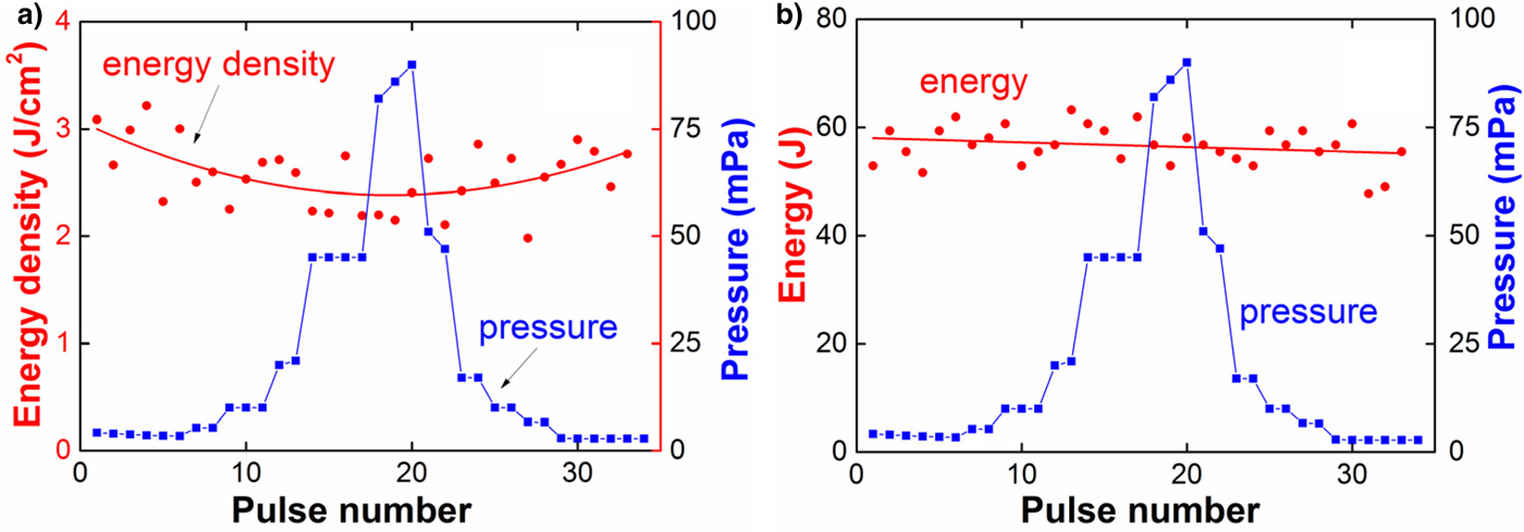
Fig. 3. Shot-to-shot variation in the HIPIB energy density and total energy vs. background pressure in a series of pulses measured directly that led to an underestimated value due to surface ablation on the target: (a) energy density, (b) total energy.
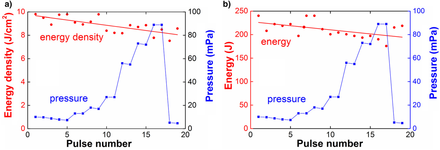
Fig. 4. Shot-to-shot variation in the HIPIB energy density and total energy vs. background pressure in a series of pulses with measurement scheme of attenuation: (a) energy density vs. pressure, (b) total energy vs. pressure.
The maximum HIPIB energy density measurement by IR diagnostics is limited by evaporation of a target material (Davis et al., Reference Davis, Bartsch, Olson, Rej and Waganaar1997). For a stainless steel target, the upper limit of energy density measurable by IR-diagnostics is 3.5–4 J/cm2. It is found that, after attenuation of an ion beam by two grids the target was heated up to a temperature slightly lower than that of target irradiated by ion beam without attenuation. Therefore, the HIPIB energy density and total energy without grids on the cathode can be estimated by taking into account a correction factor K = 2.8 for the two grids that led to a final transparency of 36%. Figure 5 shows the results of statistical measurements of HIPIB energy and energy density at a background pressure of 3–5 mPa in diode chamber. Variation of HIPIB energy and energy density at the constant pressure is about 6% (standard deviation), comparable with that of a series of pulses with varied background pressure within 1–100 mPa. Therefore, it is revealed that, insignificant decrease in HIPIB energy density with background pressure growth in the diode chamber confirmed by both modes of energy density measurements of with/without attenuation.
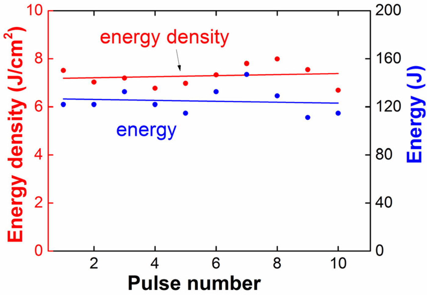
Fig. 5. Shot-to-shot variation in HIPIB energy density and full energy at a background pressure of 3–5 mPa.
3.2. HIPIB deflection
To evaluate the influence of vacuum conditions on HIPIB transportation, ion beam deflection was recorded to monitor the movement of ion beam spot center (i.e., the point of the maximum energy density on the IR image) on the target in focus in a series of pulses. Three holes in diameter of 3 mm were made on the stainless steel foil target (Fig. 2), for positioning the ion beam center movement. Figure 6 shows deviation of ion beam center position with respect to change of background pressure in diode chamber, where the beam center position denotes the distance between the HIPIB spot center and one of the three holes along vertical direction.
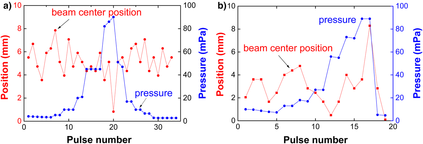
Fig. 6. Shot-to-shot variation in the ion beam deflection in vertical direction and background pressure in diode chamber: (a) low-energy density output at 3–4 J/cm2, (b) high-energy density output at 7–8 J/cm2.
Moreover, the HIPIB deflection at a constant vacuum was assessed for comparison purpose. Figure 7 presents the result of HIPIB deflection at the high-energy density output of 7–8 J/cm2, at a background pressure of 3–5 mPa in diode chamber. In this case, both vertical and horizontal movements were counted. It is shown that, moving of the HIPIB spot has little change in series of pulses as the background pressure in diode chamber is varied within 1–100 mPa. At a constant vacuum condition of 3–5 mPa, moving of the ion beam spot in series of pulses is no more than ±3 mm, and at a background pressure higher than 50 mPa, a slight increase in the beam deflection was observed, not exceeding ±4 mm. The slight increase could be attributed to increased probability of surface breakdown of the insulator and/or the breakdown of the residual gas in the diode chamber at the pressure higher than 50 mPa. In some cases, abnormal discharge could occur, such as a bright glow on the surface of the polymeric insulator leaving breakdown traces on the surface, and the corresponding total current increases abruptly.
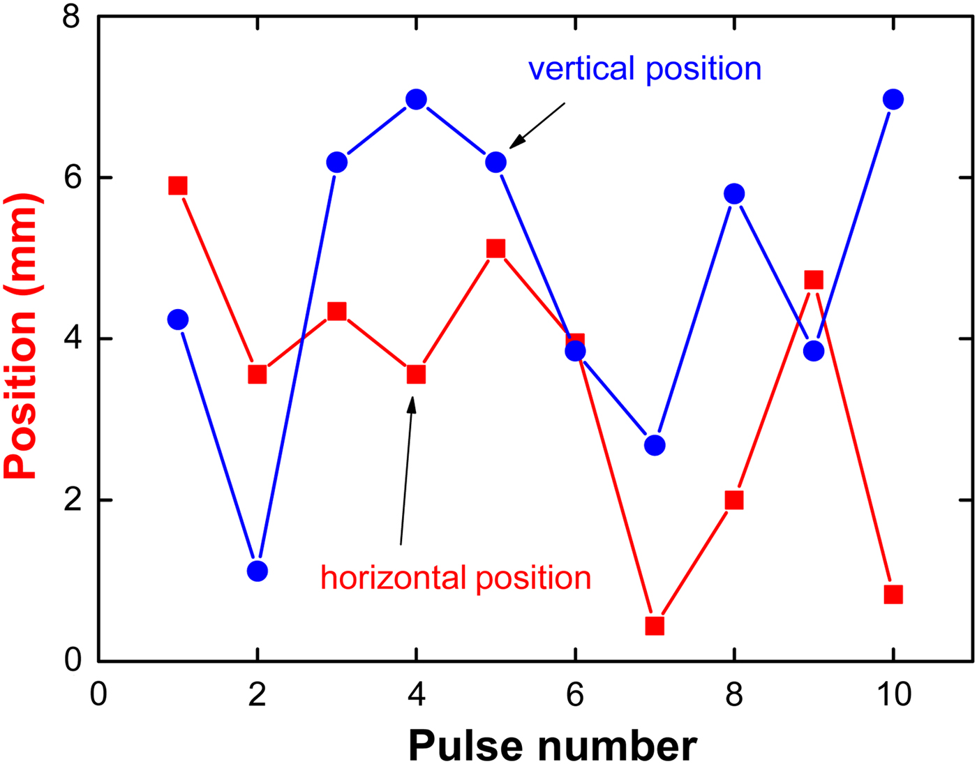
Fig. 7. Shot-to-shot variation the ion beam deflection in horizontal and vertical direction at a vacuum of 3–5 mPa.
3.3. HIPIB divergence
The HIPIB transportation characteristics were also assessed by the distribution of beam energy density in the focal plane. It is found that, variation in background pressure within 1–100 mPa has little influence on the HIPIB energy density profile in the focal plane, merely leading to slight expansion of ion beam cross-section and variation in the peak value of energy density is indistinguishable (Fig. 8). To compare the divergence of HIPIB energy density distribution at different background pressure in the chamber, the horizontal cross-section is chosen on the right hole of the target (Fig. 2). Figure 9 shows the results of ion beam divergence, defined as the ratio of the beam radius at half-height to the distance from the diode, in a series of pulses. Change of HIPIB divergence in a series of pulses has been approximated by using a straight line at least-squares method. The divergence in series of pulses was about 5.6° ± 8%, being independent on the background pressure in diode chamber.

Fig. 8. Profiles of HIPIB energy density in the focal plane along the two directions: (a) vertical direction; (b) horizontal direction, respectively, at the different background pressures in diode chamber.
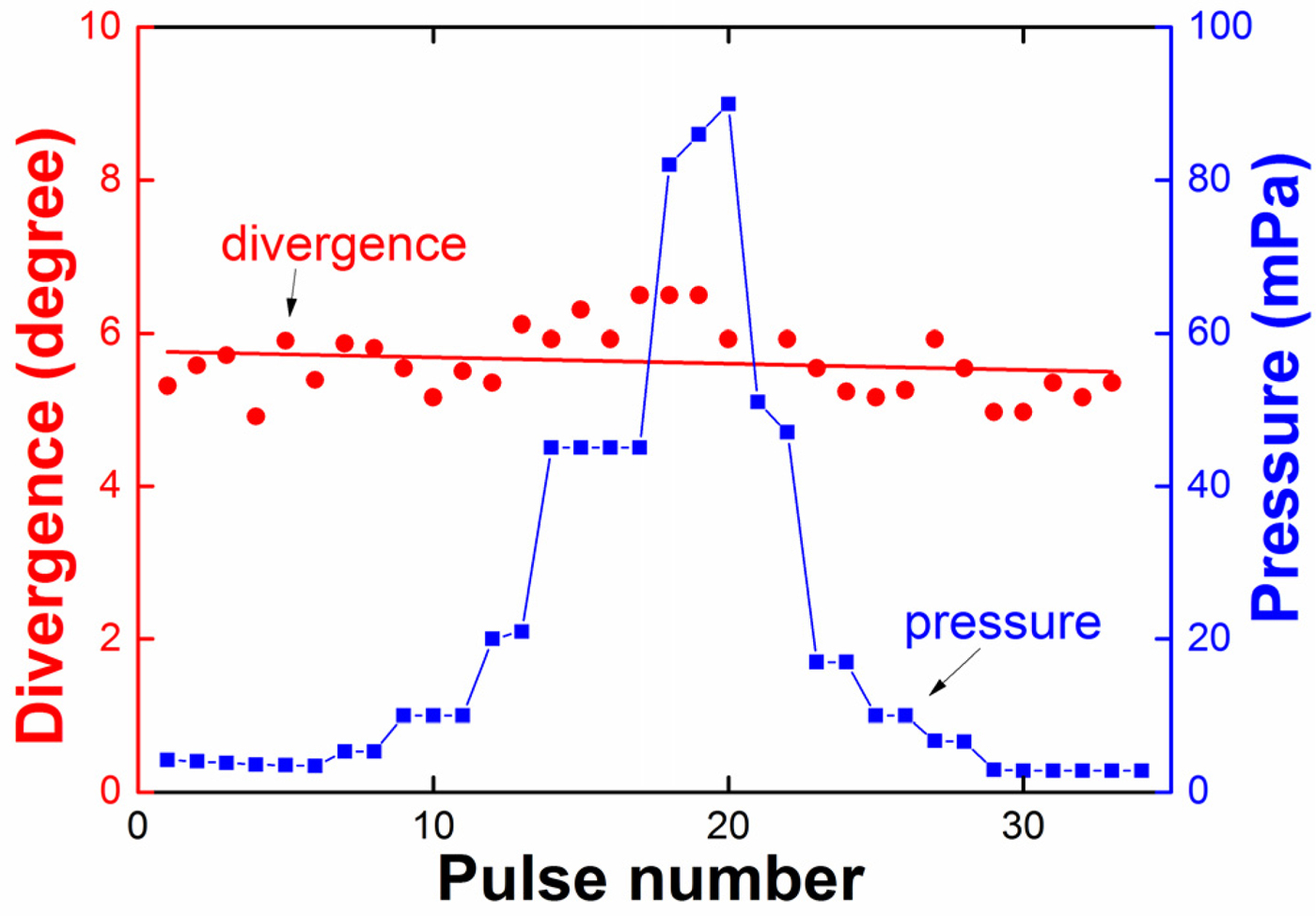
Fig. 9. Shot-to-shot variation in the ion beam divergence in vertical direction vs. background pressure in diode chamber, at low HIPIB energy density regime (3–4 J/cm2).
3.4. HIPIB full charge
It is known that a strong electric field established in intense ion beams can causes their scattering along the length of ion propagation (Bystritski & Didenko, Reference Bystritski and Didenko1989). Therefore, ion beam scattering may be mitigated or eliminated by reducing the beam-generated electric field through mixing low-energy electrons into the ion beams, that is, charge neutralization of ion beam. To evaluate the ion beam charge neutralization effect, we employed a charge collector without using magnetic field and voltage bias to receive both ions and electrons of neutralized beam. The diameter of the collector was 8 mm and the diameter of the entrance hole was 4 mm. The charge collector was located at the focus, 15 cm downstream from the diode. The waveforms of accelerating voltage, ion current density and neutralized beam current density are shown in Figure 10, respectively.

Fig. 10. Waveforms of the accelerating voltage (second pulse), ion current density, and neutralized beam current density that is measured by a charge collector covered with a 10 µm Al foil, and calculated ion current density of protons and carbon ions is also presented.
Ion current density was measured using a magnetically insulated Faraday cup (B = 0.4 T) for cutoff of electrons. Time-of-flight analysis of the HIPIB composition is performed on the measured ion current density (Figure 10). In the space-charge-limited mode, taking into account expansion of anode plasma, the ion current density can be described as follow according to the Child–Langmuir relation (Langmuir, Reference Langmuir1913):
 $$J_{{\rm ion}} = \displaystyle{{4K{\rm \varepsilon} _0 \sqrt {2z}} \over {9\sqrt m}} \cdot \displaystyle{{U^{3/2}} \over {[d_0 - v(t - t_0 )]^2}}, $$
where d 0 is the initial A–K gap, ε0 the absolute permittivity of vacuum, v the plasma expansion rate, m the ion mass, z the ion charge, t 0 the time in a bipolar pulse and at the moment the polarity on the potential electrode reverses t 0 = 500 ns (Fig. 10), and K amplification coefficient of ion current density over the Child–Langmuir limit.
Note that, the calculated values of ion current density on Eq. (1) have been increased for illustration considering the effect of HIPIB focusing on the ion current density enhancement. The enhancement factor is constant during pulse of accelerating voltage and estimated to be of a value of K H = 2 for protons and K C = 40 for C + ions, respectively. According to the results of ion beam space-charge compensation measurements, the concentration of neutralizing electrons in the focus exceeds the ion concentration by a factor of 1.1–1.2. The electrons energy does not exceed 50 keV. Figure 11 shows the charge density of HIPIB vs. background pressure in diode chamber in a series of pulses, calculated by integrating the neutralized beam current density at 550 ns < t < 750 ns (Fig. 10). Increase in background pressure in diode chamber slightly enhances the negative charge of electrons, and thus it is indicated that the variation of pressure will not essentially alter the process of HIPIB charge neutralization.
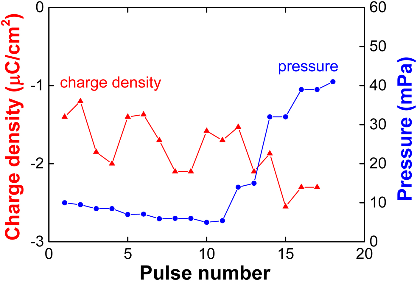
Fig. 11. Shot-to-shot variation in the ion beam charge density vs. background pressure in diode chamber.
3.5. Change of residual gas in diode chamber
Some comparative experiments on influence of vacuum conditions on HIPIB generation and transportation were carried out on accelerator TEMP-4M. Figure 12 shows the photograph of the focusing diode and HIPIB thermal imprint recorded on the target in the focal plane with a distance of 14 cm from the diode.

Fig. 12. Photograph of the MID on TEMP-4M and infrared (IR) image for energy density measurement: (a) strip focusing diode with attenuation metal mesh installed at the output of the focusing diode, 5 cm downstream from the cathode; (b) an IR image of the beam on a target at focus point, 14 cm downstream from the diode.
Figure 13 shows the results of statistical measurements of total diode current and HIPIB energy density at a background pressure of about 10 mPa in diode chamber, respectively. The pulse repetition frequency was six pulses per minute for total current measurement, and one pulse in 2 min for HIPIB energy density. The standard deviation of the energy density was 6–7% and at the same time the variation in total current was 2–3%. Figure 14 presents the results of ion beam deflection in a focal plane in a series of pulses at the background pressure of about 10 mPa. Moving of the HIPIB center in a focal plane did not exceed ±3 mm, with a standard deviation of 1.3 mm in the vertical direction and 0.6 mm in the horizontal direction.
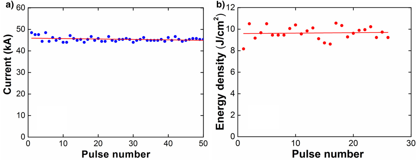
Fig. 13. Shot-to-shot variation in diode current and HIPIB energy density at a background pressure of about 10 mPa: (a) total diode current, (b) the beam energy density at the focal point.
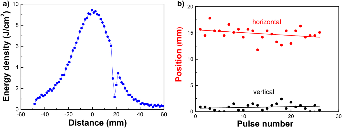
Fig. 14. Shot-to-shot variation in HIPIB deflection at the focal point under a background pressure of about 10 mPa: (a) energy density profile, (b) the ion beam deflection in both horizontal and vertical directions.
4. DISCUSSION
On the experimental data presented in this study, the effect of the background pressure on the stability of HIPIB parameters can be dealt with by concerning the ion beam generation (anode plasma generation) and transportation. The ion beam generation in the MIDs with self-magnetic insulation in the bipolar pulse mode is largely defined by processes in A–K gap during variation in the background pressure. It is estimated that, before anode surface explosive emission during the negative pulse, the adsorption of residual gas onto anode and cathode surface may lead to a superficial density at least of 1015–1016 cm−2 even merely considering several monolayers of residual gas molecules adsorbed on (diameter of molecules N2 and O2 ≈ 3 Å). These molecules are readily desorbed by explosive plasma formation at the anode and cathode surface. At explosive emission, plasma expansion rate (and corresponding speed gas layer expansion) is about 1–2 cm/μs during the first negative pulse with a duration of 400–500 ns, and thus the density of neutral molecules within А–K gap during HIPIB generation (the second pulsed) could rise to 1015–1016 cm−3 corresponding to a transient pressure of 0.3–3 Pa. Therefore, it is reasonable that increasing of background pressure in diode chamber (between pulses) to 100 mPa has little influence on the operation process of the self-magnetic field MID. It is implied that the background pressure up to 1 Pa order will not alter the plasma generation process in the A–K gap, assuming that no surface breakdown could happen in the vacuum chamber with increasing the pressure.
As for ion beam propagation in the vacuum chamber, it is found that moving of HIPIB spot center in series of pulses does not exceed ±3 mm at the considerable change of background pressure within 1–50 mPa. As the background pressure increased to a value higher than 50 mPa, it seems that a slight increase in the ion beam deflection may occur and does not exceed ±4 mm up to 90 mPa. The main mechanism for observed threshold background pressure could be occurrence of breakdown on the surface of the insulator in the diode chamber and/or the breakdown of the residual gas in the diode chamber at the pressure higher than 50 mPa. During experiments, the bright glow was observed with enhanced probability of surface breakdown in the diode chamber. In this case, the total diode current increased abruptly.
Moreover, for effective ion beam transportation, one needs to apply neutralization to create and to transport high-flux ion beams. A high ion concentration of 1010–1013 ions cm−3 in the HIPIB may lead to a change in potential up to hundreds of kilovolts. As a result, the corresponding electric field causes the scattering of intense ion beam along its length (Bystritski & Didenko, Reference Bystritski and Didenko1989). For elimination of ion beam scattering one needs to reduce the beam-generated electric field by mixing low-energy electrons with the ions. The electrons should be supplied to the ion beam volume during its transportation after extracted from the A–K gap. The executed researches have shown that the increase in background pressure in diode chamber poorly change the HIPIB charging neutralization. In the ion diode acceleration of ions occurs between a layer of anode plasma and a layer of drifting electrons near a cathode surface. In the investigated diodes the drift layer thickness is 0.3–0.5 mm at A–K gap 8–9 mm, and the electron concentration in the drifting area is (3–5)·1014 cm−3 (Pushkarev & Pak Reference Pushkarev and Pak2015). In this case, electron energy does not exceed 50 keV. With an ion current density of 100–200 A/cm2 and accelerating voltage of 250 kV, the ion concentration in HIPIB does not exceed 5·1012 cm−3 (Pushkarev et al., Reference Pushkarev, Isakova and Khailov2013). These ions pass through a thick layer of drifting low-energy electrons, which provides effective neutralization of the HIPIB. In summary, it is indicated that, the self-magnetic field MIDs are robust for ion beam generation and transportation at relatively wider range of vacuum condition in 1–100 mPa, and possibly higher if the electrical insulation in the diode system could be optimized. It is also partly proved by similar experimental phenomena on TEMP-4 M with different residual species with oil–vapor vacuum pump without a nitric trap, since the operation principle and anode material are the same as those on accelerator TEMP-6.
5. CONCLUSIONS
-
(1) HIPIB generation in the MIDs with self-magnetic field insulation using graphite anode has been investigated by controlling the residual gas pressure from 3 to 90 mPa in the diode chamber. Stable operation of the self-magnetic MIDs with repetitive ion beam output is ensured under the varied background gas pressure within 1–100 mPa.
-
(2) During plasma formation at anode and cathode occurs desorption of adsorbed molecules layer, the pressure in A–K gap increase up to 0.3–3 Pa. Therefore, the background pressure in diode chamber (between pulses) up to 1 Pa could not affect the working mode of the ion diode. However, slight increase in the ion beam deflection is observed at a pressure higher than 50 mPa. It is attributed to surface breakdown on the surface of the insulator and/or the breakdown of the residual gas in the diode chamber.
-
(3) It is found that, the ion diodes with self-magnetic field insulation may work at a moderate or even low vacuum condition if the breakdown in the diode system could be eliminated by optimized insulation design. Therefore, stable ion beam generation is feasible by using inexpensive and simple vacuum equipment for HIPIB generation; and moreover, the ion diodes with graphite anode as ion supply have long lifetime more than 106 pulses with relatively stable HIPIB generation, making their perspective for various technological applications.
ACKNOWLEDGMENTS
This work is supported by the National Natural Science Foundation of China under Grant Nos. 51371043 and 51621064, National Basic Research Program of China (973 Program) under Grant No. 2015CB057306, the Fundamental Research Funds for the Central Universities under Grant No. DUT16JJ(G)01, the 111 project of China, and the Russian Funds for Basic Research (RFBR) under Grant No. 16-48-7000012. The financial support from Collaborative Innovation Center of Major Machine Manufacturing in Liaoning is also acknowledged.


