Published online by Cambridge University Press: 30 August 2005
High gain free electron laser devices, operating in the self amplified spontaneous emission regime, are under construction and was designed as the next generation of synchrotron radiation sources. In this paper we discuss the relevant physical aspects and derive simple relations for laser and higher order harmonic power, which can usefully be exploited in the preliminary design of these sources
Research on interaction processes of intense photon beams with matter requires increasing beam intensities (Batani & Wooton, 2004; Honrubia & Tikhonchuk, 2004; Lan et al., 2004). Therefore, a significant effort was undertaken by various laboratories in Europe and USA to develop the next generation of synchrotron radiation sources, designed to achieve photon brightness (photons/sec/0.1%bw/(mm·mrad)2), with orders of magnitudes larger than that of the conventional sources (Cornacchia & Winick, 1992; Colson, 2004). Large brightness levels demand completely new conceptions either in the design of the accelerator or in the mechanisms underlying the radiation emission process. An ideally suited candidate for these devices is the high gain, self amplified, spontaneous emission free electron laser, exploiting a high quality electron beam from a high energy Linac (Alesini et al., 2004). It is well-known in these devices an intense beam of relativistic electrons is injected into a magnetic undulator, where it executes transverse oscillations, emitting, and amplifying Bremsstrahlung radiation. The E-beam drives the amplification process along the undulator, until saturation occurs (see Fig. 1), where a schematic layout of a self amplified spontaneous emission free electron laser is shown, and for further details see Ciocci et al. (2000).

SASE FEL scheme.
According to the previous remarks, this kind of device has at least two advantages with respect to an ordinary storage ring based source:
The combination of these two factors would, in principle, provide a relative increase in brightness (of ten orders of magnitude).
Furthermore, along with the emission at the fundamental, the self amplified spontaneous emission process is accompanied by a robust emission of coherent radiation at higher harmonics. This effect, known as non-linear harmonic generation, yields an extension of the tunability of the source, at shorter wavelengths, at brightness levels significantly larger than those attainable with conventional synchrotron radiation devices.
In this paper, we will review some elements of the free electron laser self amplified spontaneous emission theory including the non-linear harmonic generation effects, and present simple scaling relations for the attainable power at the various harmonics, useful in a preliminary design of these devices.
We are reminded that the radiation emitted in the undulator is centered at the wavelength

where γ = E/m0 c2 is the electron relativistic factor, λu is the undulator period, and K = eB0 λu /2πm0 c2 proportional to the magnetic on axis field B0, is the undulator strength and the request of transverse coherence imposes the condition that the beam emittance satisfies the condition:

The dynamical behavior of the self amplified spontaneous emission free electron laser is ruled by the Pierce parameter

with J being the current density (given in A/m2), λu is the undulator period (given in m), and fb(K) = J0(ξ) − J1(ξ),ξ = (1/4)(K2/(1 + K2/2) is the so-called Bessel factor correction.
The parameter ρ is the key quantity of the whole process, since it controls (Ciocci et al., 2000)


where σε is the electron beam relative energy spread


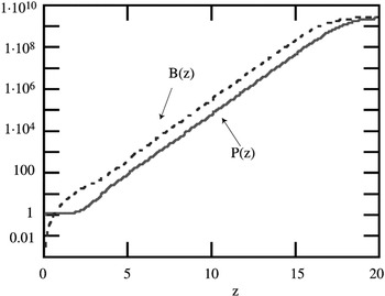
The laser power growth, up to the saturation, can be reproduced by a simple equation (Dattoli et al., 2005 and Fig. 2)

We have denoted by ZS the saturation length, namely the length of the undulator necessary to reach the final output power. The power evolution is characterized by three distinct zones, the first in which the system organizes the coherence before the E-beam bunching, leading to the second region characterized by a linear growth and the saturation.

Evolution of the laser intensity (W) vs. the undulator coordinates z (m) for a device with ρ = 1.7·10−3, λu = 2.8 cm, K = 2.145, PE = 1012 W, initial seed P0 = 1 W (continuous line) pre-bunching b1 ≅ 5.5·10−4 (dotted line).
It can be argued that Eq. (7) is more appropriate for an amplification process. It assumes, indeed, that the field grows from a coherent initial seed. It can however be modified to account for the start up from an electron beam pre-bunching, induced by the spontaneous emission, accordingly we have (Dattoli et al., 2005)

where Pb represents the equivalent seed due to the initial bunching, namely

with b1 being the bunching coefficient. The field growth according to Eq. (8) is also reported in Figure 1, which shows that, apart from a difference in the start up region, the linear growth and saturation are almost identical. The use of the previous relations allows a fairly simple understanding of what is actually needed to realize a self amplified spontaneous emission free electron laser source. In Figure 2, we considered a device operating at 12 nm with a 1 GeV beam and a current around 1 kA, with these assumptions (assuming negligible energy spread) the required undulator length is about 20 m to reach saturation. In the following section we will see how other important quantities can be reproduced in terms of analogous simple relations.
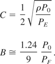
In the previous section we presented a general discussion aimed at giving an idea of the principle of operation of a self amplified spontaneous emission free electron laser device. In this section we will discuss the problems associated with non-linear harmonic generation in self amplified spontaneous emission free electron laser devices, which offer the possibility of extending the range of tunability of these sources. The free electron laser evolution is the result of a complicated interaction mechanism, involving electron beam energy modulation, bunching, coherent emission, higher order bunching, coherent emission at higher harmonics and saturation. At a macroscopic level, the saturation is due to the electron beam induced (relative) energy spread, which depends on the laser intensity itself and it is responsible of the gain reduction, eventually leading to the equilibrium conditions. The induced energy spread is, in the small signal limit, linked to the square root of the free electron laser power, this well known result allows us to parameterize it as

where B,C are constants and are given below (Dattoli et al., 2005)

It can also be checked that, at saturation Eq. (10–11) yields

In Figure 3, we provide the evolution of the self amplified spontaneous emission free electron laser power, and of the induced energy spread, as predicted by Eqs. (7 and 10), the comparison with a full numerical procedure has given an almost complete agreement.

FEL power (continuous line) and induced energy spread (dotted line) vs. the longitudinal coordinate z for ρ = 2.2·10−3, λu = 2.8 cm, K = 2.143, PE = 15 GW.
The induced energy spread is an interesting quantity for practical purposes; it can be exploited to understand the level of electron beam induced dilution. We can indeed define a characteristic length for such a process, as the undulator length necessary to get σi = ρ/2, which corresponds to

At such a length, the system is far from the saturation, but the E-beam has acquired a fairly strong bunching, which may provide a conspicuous amount of coherently generated power at higher harmonics, Eq. (9) can therefore be helpful to determine the length of a pre-bunching section in segmented undulator schemes. The possibility of emitting radiation at sub-harmonics of the fundamental is well documented in the literature (Biedron, 2001). In linearly polarized undulator the bunching may provide a significant amount of coherent radiation at odd harmonics of the fundamental, namely at λn = (λu /2nγ2)(1 + K2/2),n = 3,5… and the interest for such a mechanism is evident, since it provides a practically free extension of the tenability of the system.
The non-linear harmonic generation is a well known by product of the self amplified spontaneous emission free electron laser dynamics. The growth of the harmonic power accompanies that of the fundamental and is characterized by three distinct phases
The harmonic field growth of the field is governed by two contributions, namely the seed (1) and bunching dominated terms (2, 3), the latter can be, strictly speaking, due to a non-linear harmonic generation process.
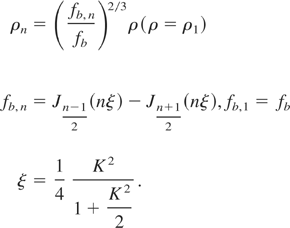
They are both present since the beginning of the interaction, but the second part, recognized as the true coherent non-linear harmonic generation contribution, becomes dominant when the induced bunching has become substantive. The key quantity ruling the harmonic field evolution is the relevant Pierce parameter ρn (where n refers to the order of the harmonics), which, for a linearly polarized undulator, writes

According to the previous discussion part (1) of the process can be written as

with An(z) obtained by replacing in Eq. (3) Lg with

where

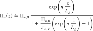
The reason of the presence of an extra factor n1/3 has been discussed in Dattoli et al. (2005) and it is a consequence of the fact that the harmonic evolution always occurs in the presence of the fundamental harmonic. As to part (1) we must underline that it is well known that the non-linear generated power is proportional to nth power of the fundamental (Ciocci et al., 2000; Biedron, 2001), so that the complete expression including saturation can be written in the form (Dattoli et al., 2005)

where the equivalent input seed Πn,0 and the harmonic saturated power Πn,F are

In conclusion, we can state that the evolution of the first and second part will be reproduced by

In Figure 4 we report the evolution of the first three odd harmonics, according to the previous equation.

Evolution of the power of the first three harmonics (1-st continuous line, 3-rd dotted line, 5-th dash line) same parameters of Figure 3.
In the previous sections we showed how very simple relationship can be exploited to study the evolution of a fairly complicated device like a self amplified spontaneous emission free electron laser. The results we obtained are a useful tool for a first design of such a device. Interesting information concerns the ratio of the intensity of higher harmonics saturated power with respect to the fundamental. In Figure 5 we reported vs. K, the ratio of the power of the higher order harmonics to the fundamental.

Ratios of the power of the third (continuous line) and fifth (dotted line) harmonic to the fundamental vs. K.
Limiting ourselves to the case of vanishing energy spread and emittances, these ratios depend on the K value only and can therefore be considered reference figures of merit to estimate the amount of brightness radiated at higher harmonics with respect to the fundamental. The parameters we used in Figures (3 and 4) are not casual, they are indeed those of the Italian project SPARC (Renieri, 2003) which foresees the use of a high quality E-beam from a Linac of maximum energy of 150 MeV to generate high brilliance self amplified spontaneous emission free electron laser radiation in the visible and VUV region of the spectrum. The project is aimed at the construction of a facility to test velocity bunching mechanisms in the compressor and coherent harmonic generation in the undulator, consisting of six identical sections with 77 periods each, where the field grows as shown in Figure 6.

Field evolution inside the undulator for λu = 2.8 cm, K = 2.1413, I = 100 A.
The SPARC project was conceived as evolutionary and was designed to pave the way for a further self amplified spontaneous emission free electron laser source which will be operated as a 4th generation synchrotron radiation facility, which is expected to provide radiation in the spectral range 13.5–1.5 nm using an up-grade of the LINAC which should bring the energy above 2 GeV and the current above 2 kA.

SASE FEL scheme.

Evolution of the laser intensity (W) vs. the undulator coordinates z (m) for a device with ρ = 1.7·10−3, λu = 2.8 cm, K = 2.145, PE = 1012 W, initial seed P0 = 1 W (continuous line) pre-bunching b1 ≅ 5.5·10−4 (dotted line).

FEL power (continuous line) and induced energy spread (dotted line) vs. the longitudinal coordinate z for ρ = 2.2·10−3, λu = 2.8 cm, K = 2.143, PE = 15 GW.

Evolution of the power of the first three harmonics (1-st continuous line, 3-rd dotted line, 5-th dash line) same parameters of Figure 3.

Ratios of the power of the third (continuous line) and fifth (dotted line) harmonic to the fundamental vs. K.

Field evolution inside the undulator for λu = 2.8 cm, K = 2.1413, I = 100 A.