


1. INTRODUCTION
The interest of scientific community in the light source of the frequency range ~1–10 terahertz (THz) is surging due to its wide-spread applications in imaging, chemical identification, remote sensing, material characterization, and explosive detection (Jiang et al., Reference Jiang, Li and Zhang2000; Ferguson & Zhang, Reference Ferguson and Zhang2002; Pickwell & Wallace, Reference Pickwell and Wallace2006; Zhong et al., Reference Zhong, Redo-Sanchez and Zhang2006; Sizov, Reference Sizov2010). Existing technologies, gyrotron, and magnetron can generate the light of GHz frequencies, but they suffer from scaling problem in THz range. Experimental schemes based on the photoconductive antenna, free electron lasers, quantum cascade lasers (Faist et al., Reference Faist, Capasso, Sivco, Sirtori, Hutchinson and Cho1994), etc. have successfully demonstrated the generation of THz radiation. The interaction of super-luminous laser pulse with electro-optic crystals and wide band gap semiconductors (like GaSe, LiNbO3, ZnTe, and ZnSe) also excite light in THz range (Faure et al., Reference Faure, Tilborg, Kanidl and Leemans2004) However, these schemes have their limitations due to the damage limit of non-linear crystals used, incoherent nature of emitted radiation and high cost associated with them. These limitations can be mitigated by using plasma as a non-linear medium, which can handle very high potential gradients and have no damage limit. Recent advancements in developing intense lasers in X rays and visible regimes provide an opportunity to generate THz radiation by frequency modulation in a plasma (Bakhtiari et al., Reference Bakhtiari, Golmohamady, Yosefl, Kashani and Ghafary2015a , Reference Bakhtiari, Yosefl, Golmohamady, Jazaayeri and Ghafary b ; Chauhan & Parashar, Reference Chauhan and Parashar2014; Dua et al., Reference Dua, Chena, Shenga and Zhanga2011; Hu et al., Reference Hu, Shen, Lei, Li and Xu2010; Liu & Tripathi, Reference Liu and Tripathi2009; Malik & Singh, Reference Malik and Singh2015; Parashar et al., Reference Parashar, Mishra and Mahajan2013; Sharma et al., Reference Sharma, Monika, Sharma, Chauhan and Jia2010; Varshney et al., Reference Varshney, Sajal, Baliyan, Sharma, Chauhan and Kumar2014a , Reference Varshney, Sajal, Chauhan, Kumar and Sharma b ).
In the present work, the frequency modulation process is carried out by beating process in a hot plasma with step density profile. Bhasin and Tripathi (Reference Bhasin and Tripathi2009) investigated THz radiation generation by the optical rectification of a picoseconds laser pulse in rippled plasma and observed that THz power is proportional to the amplitude of density ripple. Its power enhances with DC magnetic field. A ring-shape intensity distribution is obtained in azimuthal magnetic field. Conversion efficiency ~0.04% (in terms of power) is achieved using laser intensity of 3 × 10¹⁵ W/cm2 in 30% density rippled plasma. Liu et al. (Reference Liu, Houard, Prade, Aktruk, Mysyrowicz, Cowairon and Tikhonchuk2007) reported THz radiation generation in air via bifilamentation of two co-propagating laser pulses (femtosecond) with suitable time delay. The amplitude of radiation having 0.1 THz frequency radiation is enhanced ten times as compared with the one due to a single pulse for a time delay of 2 ns. A femtosecond laser pulse propagating through air undergoes filamentation and self-focusing, and form a plasma channel; a strong dipole moment is developed, which emits electromagnetic radiation. Yampolsky and Frainman (Reference Yampolsky and Frainman2006) utilized four wave coupling to excite THz radiation in a plasma-filled capillary. Two counterpropagating beating lasers exert an axial ponderomotive force on plasma electrons that drives longitudinal oscillations at plasma frequency. The beat wave parametrically excites a pair of plasma wave and a THz wave. The THz radiation propagates as transverse magnetic mode (with a small but finite electric field component in longitudinal direction) in the plasma channel. Varshney et al. (Reference Varshney, Sajal, Singh, Kumar and Sharma2013) proposed the scheme of beating by extraordinary mode lasers in a rippled density magnetized plasma. With the optimization of the parameters, the efficiency ~10−3 is achieved. Hematizadeh et al. (Reference Hematizadeh, Bakhtiari, Jazayeri and Ghafary2016) investigated the THz radiation generation by beating of two lasers in magnetized overdense plasma. Beating process achieved significant importance as a source of producing high-power THz generation utilizing its non-linear longitudinal ponderomotive force. THz radiation generation by beating lasers in a hot plasma with step density profile is proposed by Kumar et al. (Reference Kumar, Tripathi and Uk Jeong2015). In this scheme, the efficiency of THz radiation is enhanced by self-generated plasma wave. The THz power becomes zero at normal incidence and increases with the angle of incidence upto a maximum value.
In the present scheme, excitation of THz radiation generation by beating of two lasers in a hot magnetized plasma with step density profile is proposed. Step density profile plays a significant role when lasers incident obliquely on the plasma surface. Strong coupling exists between self-generated plasma wave and electromagnetic waves (excited in the plasma). Due to beating of lasers, plasma electrons undergo oscillatory motion at difference frequency and give rise to a non-linear ponderomotive force. This force may drive a non-linear current (at the beat frequency), which lies in the x–z-plane. It can excite THz radiation if resonance conditions are satisfied. In Sections 2 and 3, the expression of ponderomotive force and non-linear current density, and amplitude of THz radiation are derived, respectively. Sections 4 and 5 are dedicated for results and discussion part.
2. PONDEROMOTIVE FORCE AND NON-LINEAR DENSITY
Consider a hot magnetized plasma of electron temperature T e with step density profile
 $$\matrix{ {n{\kern 1pt} = n_0,} & {{\rm for}\;x{\rm} \gt 0,} \cr { = 0} & {{\rm for}\;x{\rm} \lt 0,} \cr} $$
where n
0 is electron plasma density. The plasma has an embedded static magnetic field
 $\vec B_{\rm s} = B_0 \hat y.$
The temperature of plasma electrons is T
e. Two co-propagating lasers of frequencies ω1 and ω2 are obliquely incident on step profile plasma at an angle θ (Fig. 1). The electric field profile of beating is as follows:
$\vec B_{\rm s} = B_0 \hat y.$
The temperature of plasma electrons is T
e. Two co-propagating lasers of frequencies ω1 and ω2 are obliquely incident on step profile plasma at an angle θ (Fig. 1). The electric field profile of beating is as follows:
 $$\vec E_j = (\hat z - \hat x\,\tan \,{\rm \theta} )\cos {\rm \theta} \,A_j e^{ - i({\rm \omega} _j - k_j (z{\kern 1pt} \sin {\rm \theta} + x\cos {\rm \theta} ))}, $$
where j = 1, 2. The electric field imparts electric force on plasma electrons, and under the influence of this force, plasma electrons start oscillating in x–z plane. Velocity components are calculated by solving equation of motion for plasma electrons.
 $$\eqalign{v_{\,jx} &= \displaystyle{{eA_j} \over {m({\rm \omega} _j^2 - {\rm \omega} _{\rm c}^2 )}}\left[ {{\rm \omega} _{\rm c} \cos {\rm \theta} + i{\rm \omega} _j \sin {\rm \theta}} \right], \cr v_{\,jz} &= \displaystyle{{eA_j} \over {m{\kern 1pt} ({\rm \omega} _j^2 - {\rm \omega} _{\rm c}^2 )}}\left[ {{\rm \omega} _{\rm c} \sin {\rm \theta} - i{\rm \omega} _j \cos {\rm \theta}} \right].} $$
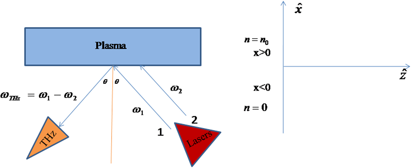
Fig. 1. Schematic for terahertz generation for the step density profile.
Beating lasers couple non-linearly at difference frequency ω = ω1 − ω2 and wave vector
 ${\bf {\vec k}} = {\bf {\vec k}}_1 - {\bf {\vec k}}_2 $
, and exert a non-linear ponderomotive force on plasma electrons in hot magnetized plasma.
${\bf {\vec k}} = {\bf {\vec k}}_1 - {\bf {\vec k}}_2 $
, and exert a non-linear ponderomotive force on plasma electrons in hot magnetized plasma.
 $$\eqalign{F_{{\rm p}x} &= \displaystyle{{ - e^2 A_1 A_2^*} \over {2m}}\left[ \matrix{\displaystyle{{(k_1 - k_2 )} \over {({\rm \omega} _1^2 - {\rm \omega} _{\rm c}^2 )({\rm \omega} _2^2 - {\rm \omega} _{\rm c}^2 )}}\left\{ \matrix{i{\rm \omega} _1 {\rm \omega} _2 \sin ^2 {\rm \theta} \,\cos ^2 {\rm \theta} - {\rm \omega} _1 {\rm \omega} _{\rm c} \sin {\rm \theta} (1 + \cos ^2 {\rm \theta} ) - {\rm \omega} _2 {\rm \omega} _{\rm c} \sin ^3 {\rm \theta} + \hfill \cr i{\rm \omega} _{\rm c}^2 \cos ^3 {\rm \theta} \hfill} \right\} \hfill \cr + \displaystyle{{i{\rm \omega} _2 k_1 \cos {\rm \theta}} \over {{\rm \omega} _1 ({\rm \omega} _2^2 - {\rm \omega} _{\rm c}^2 )}} + \displaystyle{{{\rm \omega} _{\rm c} k_1 \sin {\rm \theta}} \over {{\rm \omega} _1 ({\rm \omega} _2^2 - {\rm \omega} _{\rm c}^2 )}} - \displaystyle{{i{\rm \omega} _1 k_2 \cos {\rm \theta}} \over {{\rm \omega} _2 ({\rm \omega} _1^2 - {\rm \omega} _{\rm c}^2 )}} + \displaystyle{{{\rm \omega} _{\rm c} k_2 \sin {\rm \theta}} \over {{\rm \omega} _2 ({\rm \omega} _1^2 - {\rm \omega} _{\rm c}^2 )}} \hfill} \right], \cr F_{{\rm p}z} &= \displaystyle{{ - e^2 A_1 A_2^*} \over {2m}}\left[ \matrix{\displaystyle{{(k_1 - k_2 )} \over {({\rm \omega} _1^2 - {\rm \omega} _{\rm c}^2 )({\rm \omega} _2^2 - {\rm \omega} _{\rm c}^2 )}}\left\{ \matrix{i{\rm \omega} _1 {\rm \omega} _2 \sin {\rm \theta} \cos ^2 {\rm \theta} + {\rm \omega} _1 {\rm \omega} _{\rm c} \cos {\rm \theta} (1 + \sin ^2 {\rm \theta} ) + {\rm \omega} _2 {\rm \omega} _{\rm c} \cos ^3 {\rm \theta} + \hfill \cr i{\rm \omega} _{\rm c}^2 \sin ^3 {\rm \theta} \hfill} \right\} \hfill \cr - \displaystyle{{{\rm \omega} _{\rm c} k_1 \cos {\rm \theta}} \over {{\rm \omega} _1 ({\rm \omega} _2^2 - {\rm \omega} _{\rm c}^2 )}} + \displaystyle{{i{\rm \omega} _2 k_1 \sin {\rm \theta}} \over {{\rm \omega} _1 ({\rm \omega} _2^2 - {\rm \omega} _{\rm c}^2 )}} - \displaystyle{{i{\rm \omega} _1 k_2 \sin {\rm \theta}} \over {{\rm \omega} _2 ({\rm \omega} _1^2 - {\rm \omega} _{\rm c}^2 )}} - \displaystyle{{{\rm \omega} _{\rm c} k_2 \cos {\rm \theta}} \over {{\rm \omega} _2 ({\rm \omega} _1^2 - {\rm \omega} _{\rm c}^2 )}} \hfill} \right],} $$
where −e and m are the electronic charge and electron mass, respectively. Here * represents the complex conjugate. Here ponderomotive force is an oscillating quantity at frequency ω = ω1 − ω2 and it is represented in the complex form. Figures 2 and 3 exhibit the variation of non-linear ponderomotive force as a function of angle of incidence θ for different values of applied magnetic field and THz radiation frequencies, respectively. The non-linear ponderomotive force disturbs the plasma neutrality and plasma electrons start oscillating (at frequency ω and wave number k) in xz plane inside the plasma.
 $$\eqalign{v_{{\rm \omega} x}^{{\rm NL}} &= \displaystyle{1 \over {m{\kern 1pt} ({\rm \omega} ^2 - {\rm \omega} _{\rm c}^2 )}}\left[ {i{\rm \omega} {\kern 1pt} F_{{\rm p}x} - {\rm \omega} _{\rm c} F_{{\rm p}z}} \right], \cr v_{{\rm \omega} z}^{{\rm NL}} &= \displaystyle{1 \over {m({\rm \omega} ^2 - {\rm \omega} _{\rm c}^2 )}}\left[ {{\rm \omega} _{\rm c} F_{{\rm p}x} + i{\rm \omega} {\kern 1pt} F_{{\rm p}z}} \right].} $$
The non-linear current density is calculated by solving continuity equation.
 $$J_{\rm \omega} ^{{\rm NL}} = \displaystyle{{ - n_0 e} \over {m({\rm \omega} ^2 - {\rm \omega} _{\rm c}^2 )}}[(i{\rm \omega} + {\rm \omega} _{\rm c} )F_{{\rm p}x} \hat x + (i{\rm \omega} - {\rm \omega} _{\rm c} )F_{{\rm p}z} \,\hat z].$$
The non-linear current density in xz plane would excite p-polarized THz wave associated with a space charge mode. Suppose the self-consistent electric field of this combined mode be
 $\vec E_{\rm \omega} = \vec A(x)e^{ - i({\rm \omega} t - k_z z)} $
, where k
z
= k
1z
− k
2z
The plasma electrons start oscillating under the influence of this self-consistent field. The oscillatory velocity of plasma electrons is calculated by solving equation of motion
$\vec E_{\rm \omega} = \vec A(x)e^{ - i({\rm \omega} t - k_z z)} $
, where k
z
= k
1z
− k
2z
The plasma electrons start oscillating under the influence of this self-consistent field. The oscillatory velocity of plasma electrons is calculated by solving equation of motion
 $[m\partial {\vec v\,}_{\rm \omega} ^{\rm L} /\partial t = - e\vec E_{\rm \omega} - mv_{{\rm th}}^2 \nabla n_{\rm \omega} /n_0 - e({\vec v\,}_{\rm \omega} ^{\rm L} \times \vec B_{\rm S} )]$
and Poisson's equation
$[m\partial {\vec v\,}_{\rm \omega} ^{\rm L} /\partial t = - e\vec E_{\rm \omega} - mv_{{\rm th}}^2 \nabla n_{\rm \omega} /n_0 - e({\vec v\,}_{\rm \omega} ^{\rm L} \times \vec B_{\rm S} )]$
and Poisson's equation
 $(\nabla. \vec E_{\rm \omega} = - n_{\rm \omega} e/{\rm \varepsilon} _0 )$
simultaneously. Here ε0 and v
th are the permittivity of the free space and thermal velocity of the electron, respectively. The oscillatory velocity
$(\nabla. \vec E_{\rm \omega} = - n_{\rm \omega} e/{\rm \varepsilon} _0 )$
simultaneously. Here ε0 and v
th are the permittivity of the free space and thermal velocity of the electron, respectively. The oscillatory velocity
 $v_{\rm \omega} ^{\rm L} $
of plasma electrons is given by
$v_{\rm \omega} ^{\rm L} $
of plasma electrons is given by
 $${\vec v\,}_{\rm \omega} ^{\rm L} = \displaystyle{{e\vec E_{\rm \omega}} \over {mi{\rm \omega}}} + \displaystyle{e \over {mi{\rm \omega}}} ({\vec v\,}_{\rm \omega} ^{\rm L} \times \vec B_{\rm s} ) - \displaystyle{{v_{{\rm th}}^2 {\rm \varepsilon} _0} \over {n_0 ie{\rm \omega}}} \nabla (\nabla. \vec E).$$
The linear current density due to oscillatory motion of plasma electrons is as follows:
 $${\vec J\,}_{\rm \omega} ^{{\rm L}^{\rm ^{\prime}}} = {\vec J\,}_{\rm \omega} ^{\rm L} + \displaystyle{{v_{{\rm th}}^2 {\rm \varepsilon} _0} \over {i{\rm \omega}}} \nabla \left( {\nabla. \vec E} \right),$$
where
 $${\vec J\,}_{\rm \omega} ^{\rm L} = - \displaystyle{{n_0 e^2 E_{\rm \omega}} \over {mi{\rm \omega}}} - \displaystyle{{n_0 e^2} \over {mi{\rm \omega}}} ({\vec v\,}_{\rm \omega} ^{\rm L} \times \vec B_{\rm s} ) = {\bar {\bar {\rm \sigma}}}. \vec E.$$
Here
 ${\bar {\bar {\rm \sigma}}} $
is conductivity tensor. One should note that oscillating physical quantities like plasma velocity and conductivity tensors are used in complex notations in the present manuscript.
${\bar {\bar {\rm \sigma}}} $
is conductivity tensor. One should note that oscillating physical quantities like plasma velocity and conductivity tensors are used in complex notations in the present manuscript.

Fig. 2. Real and imagionary parts (f pz r and f pz im) of normalized amplitude of the reflected THz wave (eA r/mωp c)as a function of angle of incidence θ for different values of magnetic field at frequency 1.1 THz.

Fig. 3. Normalized ponderomotive force (f pz ) as a function of angle of incidence θ for different values of magnetic field B s at normalized frequency ω = 1.1 THz.
3. AMPLITUDE OF THz RADIATION
The wave equation governing THz radiation is given by
 $$\nabla ^2 \vec E_{\rm \omega} - \left( {1 - \displaystyle{{v_{{\rm th}}^2} \over {c^2}}} \right)\nabla (\nabla. \vec E_{\rm \omega} ) = - \displaystyle{{i{\rm \omega}} \over {c^2 {\rm \varepsilon} _0}} {\vec J\,}_{\rm \omega} ^{{\rm NL}} - \displaystyle{{{\rm \omega} ^2} \over {c^2}} {\bar {\bar {\rm \varepsilon}}} \,\vec E_{\rm \omega}, $$
where
 $${\bar {\bar {\rm \varepsilon}}} = {\rm \varepsilon} _0 \left( {{\bar {\bar I}} + \displaystyle{{i{\bar {\bar {\rm \sigma}}}} \over {{\rm \omega \varepsilon} _0}}} \right).$$
This equation offers two solutions in the absence of the non-linear source. First solution is a Langmuir wave
 $\vec E_{\rm s} = A_{\rm s} (\hat x + (k_z /k_{{\rm s}x} )\hat z)e^{ik_{{\rm s}x} x} e^{ - i({\rm \omega} t - k_z z)} $
with
$\vec E_{\rm s} = A_{\rm s} (\hat x + (k_z /k_{{\rm s}x} )\hat z)e^{ik_{{\rm s}x} x} e^{ - i({\rm \omega} t - k_z z)} $
with
 $\nabla \times \vec E = 0$
; and second solution is an electromagnetic wave
$\nabla \times \vec E = 0$
; and second solution is an electromagnetic wave
 $\vec E_{\rm m} = A_{\rm m} (\hat x - (k_{{\rm m}x} /k_z )\hat z)e^{ik_{{\rm m}x} x} e^{ - i({\rm \omega} t - k_z z)} $
with
$\vec E_{\rm m} = A_{\rm m} (\hat x - (k_{{\rm m}x} /k_z )\hat z)e^{ik_{{\rm m}x} x} e^{ - i({\rm \omega} t - k_z z)} $
with
 $\nabla. \vec E = 0$
where
$\nabla. \vec E = 0$
where
 $$\eqalign{k_{{\rm s}x} &= \displaystyle{1 \over {v_{{\rm th}}}} \left[ {\displaystyle{{({\rm \omega} ^2 - {\rm \omega} _{\rm h}^2 ){\rm \omega} ^2} \over {{\rm \omega} ^2 - {\rm \omega} _{\rm c}^2}} + \displaystyle{{{\rm \omega \omega} _{\rm c} {\rm \omega} _{\rm p}^2} \over {{\rm \omega} ^2 - {\rm \omega} _{\rm c}^2}} - k_z^2 v_{{\rm th}}^2} \right]^{1/2}, \cr k_{{\rm m}x} &= \displaystyle{1 \over c}\left[ {\displaystyle{{({\rm \omega} ^2 - {\rm \omega} _{\rm h}^2 ){\rm \omega} ^2} \over {{\rm \omega} ^2 - {\rm \omega} _{\rm c}^2}} + \displaystyle{{{\rm \omega \omega} _{\rm c} {\rm \omega} _{\rm p}^2} \over {{\rm \omega} ^2 - {\rm \omega} _{\rm c}^2}} - k_z^2 {\kern 1pt} c^2} \right]^{1/2}.} $$
Above-mentioned expressions of k sx and k mx also represent the dispersion relation for Langmuir wave and electromagnetic waves (in the absence of non-linear source term) in plasma, respectively. One should note that hot plasma is must for propagating electrostatic wave mentioned in Eq. (9). In a cold plasma, one will have only damped oscillations.
In the presence of a non-linear source term on the right-hand side of Eq. (9), a particular solution exists. The oscillating field still varies as
 $e^{ - i({\rm \omega} t - \vec k.\vec r)} $
and can be written as,
$e^{ - i({\rm \omega} t - \vec k.\vec r)} $
and can be written as,
 $\vec E_{\rm p} = i{\rm \omega} \vec J_{\rm \omega} ^{{\rm NL}} /[{\rm \varepsilon} _0 ({\rm \omega} ^2 - {\rm \omega} _{\rm p}^2 - k^2 v_{{\rm th}}^2 )]$
whose amplitude in the x and z directions are as follows:
$\vec E_{\rm p} = i{\rm \omega} \vec J_{\rm \omega} ^{{\rm NL}} /[{\rm \varepsilon} _0 ({\rm \omega} ^2 - {\rm \omega} _{\rm p}^2 - k^2 v_{{\rm th}}^2 )]$
whose amplitude in the x and z directions are as follows:
 $$\eqalign{A_{x{\rm p}} &= \displaystyle{i \over {{\rm \varepsilon} _0 {\rm \omega} ^3}} [({\rm \omega} ^2 {\rm \varepsilon} _{zz} - k^2 v_{{\rm th}}^2 )J_{{\rm \omega} x}^{{\rm NL}} - {\rm \omega} ^2 {\rm \varepsilon} _{xz} J_{{\rm \omega} z}^{{\rm NL}} ]/{\rm \varepsilon} _{{\rm \omega}, {\rm k}}, \cr A_{z{\rm p}} &= \displaystyle{i \over {{\rm \varepsilon} _0 {\rm \omega} ^3}} [({\rm \omega} ^2 {\rm \varepsilon} _{xx} - k^2 v_{{\rm th}}^2 )J_{{\rm \omega} z}^{{\rm NL}} - {\rm \omega} ^2 {\rm \varepsilon} _{zx} J_{{\rm \omega} x}^{{\rm NL}} ]/{\rm \varepsilon} _{{\rm \omega, k}},} $$
where
 ${\rm \varepsilon} _{{\rm \omega}, k} = {\rm \varepsilon} _{xz} {\rm \varepsilon} _{zx} - (({\rm \omega} ^2 {\rm \varepsilon} _{xx} - k^2 v_{{\rm th}}^2 )^{1/2} /{\rm \omega} ^4 )$
There is no magnetic field associated with
${\rm \varepsilon} _{{\rm \omega}, k} = {\rm \varepsilon} _{xz} {\rm \varepsilon} _{zx} - (({\rm \omega} ^2 {\rm \varepsilon} _{xx} - k^2 v_{{\rm th}}^2 )^{1/2} /{\rm \omega} ^4 )$
There is no magnetic field associated with
 $\vec E_{\rm s} $
and
$\vec E_{\rm s} $
and
 $\vec E_{\rm p} $
because
$\vec E_{\rm p} $
because
 $\nabla \times \vec E_{\rm s} = 0$
and
$\nabla \times \vec E_{\rm s} = 0$
and
 $\nabla \times \vec E_{\rm p} = 0$
. The magnetic field associated with
$\nabla \times \vec E_{\rm p} = 0$
. The magnetic field associated with
 $\vec E_{\rm m} $
is calculated by solving third Maxwell's equation.
$\vec E_{\rm m} $
is calculated by solving third Maxwell's equation.
 $$\vec H_{\rm m} = \hat y\displaystyle{{k_{{\rm m}x}^2 + k_z^2} \over {{\rm \mu} _0 {\rm \omega} k_z}} A_{\rm m} {\kern 1pt} e^{ik_{\rm m} x} e^{ - i({\rm \omega} t - k_z z)}. $$
As compared with fields
 $\vec E_{\rm s} $
,
$\vec E_{\rm s} $
,
 $\vec E_{\rm m} $
, and
$\vec E_{\rm m} $
, and
 $\vec E_{\rm p} $
, which exist in x > 0 region, there exists only outgoing THz field in x < 0 region. The electric field profile of outgoing THz wave can be written as follow:
$\vec E_{\rm p} $
, which exist in x > 0 region, there exists only outgoing THz field in x < 0 region. The electric field profile of outgoing THz wave can be written as follow:
 $$\eqalign{\vec E_{\rm R} &= A_{\rm r} \left( {\hat x + \displaystyle{{k_x} \over {k_z}} \hat z} \right)e^{ - ik_x x} e^{ - i({\rm \omega} t - k_z z)}, \cr \vec H_{\rm R} &= \hat y\displaystyle{{k_x^2 + k_z^2} \over {{\rm \mu} _0 {\rm \omega} k_z}} A_{\rm r} e^{ - ik_x x} e^{ - i({\rm \omega} t - k_z z)}.} $$
Boundary conditions are employed to correlate fields in regions x < 0 and x > 0. E z and H y must be continuous at vacuum plasma interface x = 0. The third boundary condition is calculated from the z-component of Eq. (9), by integrating it over x from 0− to 0+, to obtain
 $$\left( {\displaystyle{{\partial E_z} \over {\partial x}} - ik_z \left( {1 - v_{{\rm th}}^2 /c^2} \right)E_x} \right)_{0^ +} = \left( {\displaystyle{{\partial E_z} \over {\partial x}} - ik_z E_x} \right)_{0^ -}. $$
Using above mentioned boundary conditions, we have
 $$\eqalign{& - \displaystyle{{k_{{\rm m}x}} \over {k_z}} A_{\rm m} \cr & + \displaystyle{{k_z} \over {k_{{\rm s}x}}} A_{\rm s} + \displaystyle{i \over {{\rm \varepsilon} _0 {\rm \omega} ^3}} \left( {\displaystyle{{({\rm \omega} ^2 \varepsilon _{xx} - k^2 v_{{\rm th}}^2 )J_{{\rm \omega} z}^{{\rm NL}} - {\rm \omega} ^2 {\rm \varepsilon} _{zx} J_{{\rm \omega} x}^{{\rm NL}}} \over {{\rm \varepsilon} _{{\rm \omega, k}}}}} \right) \cr & = \displaystyle{{k_x} \over {k_z}} A_{\rm r},}$$
 $$A_{\rm m} = \displaystyle{{k_x^2 + k_z^2} \over {k_{{\rm m}x}^2 + k_z^2}} A_{\rm r}, $$
 $$\eqalign{& \left( {k_{{\rm m}x}^2 + k_z^2 \left( {1 - v_{{\rm th}}^2 /c^2} \right)} \right)A_{\rm m} - k_z^2 \left( {v_{{\rm th}}^2 /c^2} \right)A_{\rm s} - \displaystyle{{ik_x k_z} \over {{\rm \varepsilon} _0 {\rm \omega} ^3}} \cr & \left( {\displaystyle{{({\rm \omega} ^2 {\rm \varepsilon} _{xx} - k^2 v_{{\rm th}}^2 )J_{{\rm \omega} z}^{{\rm NL}} - {\rm \omega} ^2 {\rm \varepsilon} _{zx} J_{{\rm \omega} x}^{{\rm NL}}} \over {{\rm \varepsilon} _{{\rm \omega, k}}}}} \right) + k_z^2 \left( {1 - v_{{\rm th}}^2 /c^2} \right) \cr & \left( {\displaystyle{i \over {{\rm \varepsilon} _0 {\rm \omega} ^3}} \displaystyle{{({\rm \omega} ^2 {\rm \varepsilon} _{zz} - k^2 v_{{\rm th}}^2 )J_{{\rm \omega} x}^{{\rm NL}} - {\rm \omega} ^2 {\rm \varepsilon} _{xz} J_{{\rm \omega} z}^{{\rm NL}}} \over {{\rm \varepsilon} _{{\rm \omega}, k}}}} \right) = \left( {k_x^2 + k_z^2} \right)A_{\rm r}.} $$
The amplitude of outgoing THz wave is obtained by solving Eqs (14)–(16) simultaneously
 $$\eqalign{A_{\rm r} & = \displaystyle{{(k_{{\rm m}x}^2 + k_z^2 )} \over {v_{{\rm th}}^2 /c^2 [k_{{\rm m}x}^2 k_x k_{{\rm s}x} + k_z^2 k_x k_{{\rm s}x} + k_z^2 k_x^2 + k_{{\rm m}x} k_{{\rm s}x} k_x^2 + k_z^4 + k_z^2 k_{{\rm m}x} k_{{\rm s}x} ]}} \cr & \quad \left[ \matrix{\displaystyle{{ik_z k_{{\rm s}x} v_{{\rm th}}^2 /c} \over {{\rm \varepsilon} _0 {\rm \omega} ^3}} \left( {\displaystyle{{({\rm \omega} ^2 {\rm \varepsilon} _{xx} - k^2 v_{{\rm th}}^2 )J_{{\rm \omega} z}^{{\rm NL}} - {\rm \omega} ^2 {\rm \varepsilon} _{zx} J_{{\rm \omega} x}^{{\rm NL}}} \over {{\rm \varepsilon} _{{\rm \omega}, k}}}} \right) - \displaystyle{{ik_x k_z} \over {{\rm \varepsilon} _0 {\rm \omega} ^3}} \left( {\displaystyle{{({\rm \omega} ^2 {\rm \varepsilon} _{xx} - k^2 v_{th}^2 )J_{{\rm \omega} z}^{{\rm NL}} - {\rm \omega} ^2 {\rm \varepsilon} _{zx} J_{{\rm \omega} x}^{{\rm NL}}} \over {{\rm \varepsilon} _{{\rm \omega}, k}}}} \right) + \hfill \cr k_z^2 (1 - v_{{\rm th}}^2 /c^2 )\displaystyle{i \over {{\rm \varepsilon} _0 {\rm \omega} ^3}} \left( {\displaystyle{{({\rm \omega} ^2 {\rm \varepsilon} _{zz} - k^2 v_{{\rm th}}^2 )J_{{\rm \omega} x}^{{\rm NL}} - {\rm \omega} ^2 {\rm \varepsilon} _{xz} J_{{\rm \omega} z}^{{\rm NL}}} \over {{\rm \varepsilon} _{{\rm \omega}, k}}}} \right) \hfill} \right].} $$
4. RESULTS
Equation (17) is solved numerically for the given parameters: a
1 = eA
1/mω1
c = 0.1, a
2 = eA
2/mω2
c = 0.1, θ = 5° − 90°, and v
th = 0.03c. Figure 2 exhibits the variation in normalized amplitude of the reflected THz wave (eA
r/mωp
c) as a function of angle of incidence θ for different values of magnetic field at ω = 1.1 THz. The amplitude of THz radiation increases with applied (transverse) DC magnetic field. Two peaks are obtained corresponding to
 ${\rm \theta} _{\rm s} \sim 10 $
° and θs ~ 50°–60°. The dip between two peaks shifts toward higher value of θs as magnetic field increases. These peaks are corresponding to the variation of non-linear ponderomotive force as shown in Figures 3 and 4. Real part of ponderomotive force is in z-direction, f pz
r is responsible for amplitude peak at θs ~ 10°,while imaginary part of ponderomotive force f pz
im is responsible for peak at θs ~ 50°–60°. In the absence of magnetic field f pz
r = 0; only f pz
im exists; consequently only one peak at θs ~ 50° survives without DC magnetic field (Fig. 5). Figure 6 shows the variation of THz wave amplitude as a function of angle of incidence θ for different values of radiation frequency at magnetic field B
s = 1071 G. Again, two THz amplitude peaks are obtained at θ ~ 12° and θ = 50–70°. Peak height of THz amplitude at lower angle reduces with radiation frequency, while peak at higher angle enhances in height but shifts toward higher angle with radiation frequency. This trend is corresponding to the variation of f pz
r and f pz
im with radiation frequency in Figures 3 and 4).
${\rm \theta} _{\rm s} \sim 10 $
° and θs ~ 50°–60°. The dip between two peaks shifts toward higher value of θs as magnetic field increases. These peaks are corresponding to the variation of non-linear ponderomotive force as shown in Figures 3 and 4. Real part of ponderomotive force is in z-direction, f pz
r is responsible for amplitude peak at θs ~ 10°,while imaginary part of ponderomotive force f pz
im is responsible for peak at θs ~ 50°–60°. In the absence of magnetic field f pz
r = 0; only f pz
im exists; consequently only one peak at θs ~ 50° survives without DC magnetic field (Fig. 5). Figure 6 shows the variation of THz wave amplitude as a function of angle of incidence θ for different values of radiation frequency at magnetic field B
s = 1071 G. Again, two THz amplitude peaks are obtained at θ ~ 12° and θ = 50–70°. Peak height of THz amplitude at lower angle reduces with radiation frequency, while peak at higher angle enhances in height but shifts toward higher angle with radiation frequency. This trend is corresponding to the variation of f pz
r and f pz
im with radiation frequency in Figures 3 and 4).

Fig. 4. Real and imagionary parts (f pz r and f pz im) of normalized ponderomotive force (f pz ) as a function of angle of incidence θfor different values of normalized frequency at magnetic field B s = 1071 G.

Fig. 5. Normalized amplitude of the reflected THz wave (eA r/mωp c)as a function of angle of incidence θ for different values of THz wave frequency without any external field.

Fig. 6. Normalized amplitude of the reflected THz wave (eA r/mωp c)as a function of angle of incidence θ for different values of THz wave frequency with applied DC field B s = 1071 G.
5. DISCUSSION
Excitation of THz radiation by non-linear mixing of two obliquely incident laser beams in step density magnetized plasma is an attractive alternative because (i) the scheme can be easily realized and (ii) it provides higher efficiency due to coupling between THz radiation and plasma wave. In the presence of transverse magnetic field, obliquely incident p-polarized beating lasers excite a non-linear surface current, which is responsible for THz radiation generation at resonance. For a particular (applied) magnetic field, THz amplitude can be optimized at a particular angle (i.e. incident angle of lasers), for example, maximum THz radiation amplitude of frequency 1.1 THz is achieved at an optimum angle ~60° for B
s = 1785 G. Optimum angle changes its position with THz radiation frequency and applied magnetic field due to change in resonance position. In the absence of transverse magnetic field, only one peak in THz amplitude is observed (Fig. 5), while two peaks along with a dip are observed in the presence of applied magnetic field (Fig. 6). Two peaks are obtained due to change in polarization of THz radiation. Now, THz radiation propagates in the form of extraordinary wave, which has two branches at different frequencies. Two peaks in Figure 6 are corresponding to these branches. The dip between two peaks represents the damping regime, which is corresponding to resonance at which wave dumps its energy to plasma electrons. Applied magnetic field changes not only the amplitude and the polarization of THz wave, but it also introduces an imaginary part to the ponderomotive force, which represents the phase difference between
 $\vec F_{\rm p} $
and
$\vec F_{\rm p} $
and
 $\vec E_{1,2} $
of beating lasers. Transverse magnetic field also controls the phase velocity and group velocity of THz radiation. Hot plasma is used to introduce frequency selectivity and for better coupling between Langmuir wave and THz radiation. In the present scheme, frequencies of beating lasers are ~100 THz, which corresponding to CO2 laser. THz amplitude increases with applied magnetic field and radiation frequency due to enhanced coupling. Reduction in efficiency due to the collision of electrons is ignored in this scheme. In the present scheme, the kinetic effects are also ignored in deducing drift velocity due to ponderomotive force because ω ≫ kv
th. For the electron response, isothermal approximation is inferred. The adiabatic approximation can be valid by appropriately multiplying the temperature of electron with the ratio of specific heats at constant volume and constant pressure. In this analysis, the effect of finite beam size is ignored as beating lasers are incident obliquely on plasma–vacuum interface. When angle of incidence becomes zero, non-linear current density does not have the transverse component and THz emission does not take place. The THz amplitude 8 × 10⁸ V/m is turned out for laser intensity 3 × 10⁸ W/cm2, wavelength 1 µm and spot size 100 µm. Analytical investigations show that the present scheme is quite effective for excitation of THz wave.
$\vec E_{1,2} $
of beating lasers. Transverse magnetic field also controls the phase velocity and group velocity of THz radiation. Hot plasma is used to introduce frequency selectivity and for better coupling between Langmuir wave and THz radiation. In the present scheme, frequencies of beating lasers are ~100 THz, which corresponding to CO2 laser. THz amplitude increases with applied magnetic field and radiation frequency due to enhanced coupling. Reduction in efficiency due to the collision of electrons is ignored in this scheme. In the present scheme, the kinetic effects are also ignored in deducing drift velocity due to ponderomotive force because ω ≫ kv
th. For the electron response, isothermal approximation is inferred. The adiabatic approximation can be valid by appropriately multiplying the temperature of electron with the ratio of specific heats at constant volume and constant pressure. In this analysis, the effect of finite beam size is ignored as beating lasers are incident obliquely on plasma–vacuum interface. When angle of incidence becomes zero, non-linear current density does not have the transverse component and THz emission does not take place. The THz amplitude 8 × 10⁸ V/m is turned out for laser intensity 3 × 10⁸ W/cm2, wavelength 1 µm and spot size 100 µm. Analytical investigations show that the present scheme is quite effective for excitation of THz wave.


