


Introduction
Acceleration of solid or dense plasma projectiles to hyper velocities is a topic of high relevance for contemporary research in high energy density physics (Drake, Reference Drake2006; Nellis, Reference Nellis2016) and inertial confinement fusion (ICF) (Atzeni and Meyer-ter-Vehn, Reference Atzeni and Meyer-ter-Vehn2004; Murakami et al., Reference Murakami, Nagatomo, Johzaki, Sakaiya, Velikovich, Karasik, Guskov and Zmitrenko2014). Moreover, it finds applications in space research (Friichtenicht & Becker, Reference Friichtenicht and Becker1971; Thornhill et al., Reference Thornhill, Chabildas, Reinhart and Davidson2006) and materials science, particularly in the studies of materials subject to high mechanical loads (Mitchell et al., Reference Mitchell, Nellis, Mariorty, Heinle, Holmes, Tipton and Repp1991; Nellis, Reference Nellis2016). To achieve the projectile parameters useful for these research, various accelerating devices and acceleration schemes have been proposed and investigated. These include Van de Graaf accelerators (Friichtenicht & Becker, Reference Friichtenicht and Becker1971), light-gas guns (Mitchell et al., Reference Mitchell, Nellis, Mariorty, Heinle, Holmes, Tipton and Repp1991; Nellis, Reference Nellis2016), pulsed-power machines (Lemke et al., Reference Lemke, Knudson, Bliss, Cochrane, Davis, Giunta, Harjes and Slutz2005), and laser-driven accelerators (Obenschain et al., Reference Obenschain, Whitlock, McLean, Ripin, Price, Phillion, Campbell, Rosen and Aurbach1983; Cauble et al., Reference Cauble, Phillion, Hoover, Holmes, Kilkenny and Lee1993; Ozaki et al., Reference Ozaki, Sasatani, Kishida, Nakano, Miyanaga, Nagai, Nishihara, Norimatsu, Tanaka, Fujimoto, Wakabayashi, Hattori, Tange, Kondo, Yoshida, Kozu, Ishiguchi and Takenaka2001; Atzeni and Meyer-ter-Vehn, Reference Atzeni and Meyer-ter-Vehn2004; Karasik et al., Reference Karasik, Weaver, Aglitskiy, Watari, Arikawa, Sakaiya, Oh, Velikovich, Zalesak, Bates, Obenschain, Schmitt, Murakami and Azechi2010; Frantaduono et al., Reference Frantaduono, Smith, Boehly, Eggert, Braun and Collins2012; Murakami et al., Reference Murakami, Nagatomo, Johzaki, Sakaiya, Velikovich, Karasik, Guskov and Zmitrenko2014; Shui et al., Reference Shui, Chu, Xin, Wu, Zhu, He, Xi and Gu2015, Reference Shui, Chu, Zhu, He, Xi, Fan, Xin and Gu2016). Among these, the laser-driven accelerators generate projectiles (usually dense plasma projectiles) of highest velocities up to ~100–1000 km/s (Karasik et al., Reference Karasik, Weaver, Aglitskiy, Watari, Arikawa, Sakaiya, Oh, Velikovich, Zalesak, Bates, Obenschain, Schmitt, Murakami and Azechi2010; Murakami et al., Reference Murakami, Nagatomo, Johzaki, Sakaiya, Velikovich, Karasik, Guskov and Zmitrenko2014) and have the potential to achieve even sub-relativistic projectile velocities (Yu et al., Reference Yu, Xu, He, Yu, Ishiguro, Zhang and Wong2005; Badziak & Jabłoński, Reference Badziak and Jabłoński2011). The laser-based scheme most commonly used for the acceleration of plasma projectiles is the so-called ablative acceleration (AA) (Atzeni & Meyer-ter-Vehn, Reference Atzeni and Meyer-ter-Vehn2004). In this scheme, the surface of a solid target is irradiated by the laser beam or the laser-produced soft X-ray radiation, which leads to the creation of hot plasma expanding backward, thus accelerating the remaining denser part of the target (the projectile) in the forward direction via the “rocket effect”. In particular, the AA scheme is used to drive and compress the hydrogen fuel in fusion targets (Atzeni & Meyer-ter-Vehn, Reference Atzeni and Meyer-ter-Vehn2004; Hurricane et al., Reference Hurricane, Callahan, Casey, Celliers, Cerjan, Dewald, Dittrich, Döppner, Hinkel, Berzak, Hopkins, Kline, Le Pape, MacPhee, Milovich, Pak, Park, Patel, Remington, Salmonson, Springer and Tommasini2014) or to accelerate a projectile to ignite the compressed fuel by the impact (Azechi et al., Reference Azechi, Sakaiya, Watari, Karasik, Saito, Ohtani, Takeda, Hosoda, Shiraga, Nakai, Shigemori, Fujioka, Murakami, Nagatomo, Johzaki, Gardner, Colombant, Bates, Velikovich, Aglitskiy, Weaver, Obenschain, Eliezer, Kodama, Norimatsu, Fujita, Mima and Kan2009; Murakami et al., Reference Murakami, Nagatomo, Johzaki, Sakaiya, Velikovich, Karasik, Guskov and Zmitrenko2014). Unfortunately, this scheme has low energetic efficiency of the acceleration ηacc = E p/E L (E p is the kinetic energy of the projectile and E L is the laser energy), which in practice attains values in the range of 0.5–3% (Cauble et al., Reference Cauble, Phillion, Hoover, Holmes, Kilkenny and Lee1993; Ozaki et al., Reference Ozaki, Sasatani, Kishida, Nakano, Miyanaga, Nagai, Nishihara, Norimatsu, Tanaka, Fujimoto, Wakabayashi, Hattori, Tange, Kondo, Yoshida, Kozu, Ishiguchi and Takenaka2001; Azechi et al., Reference Azechi, Sakaiya, Watari, Karasik, Saito, Ohtani, Takeda, Hosoda, Shiraga, Nakai, Shigemori, Fujioka, Murakami, Nagatomo, Johzaki, Gardner, Colombant, Bates, Velikovich, Aglitskiy, Weaver, Obenschain, Eliezer, Kodama, Norimatsu, Fujita, Mima and Kan2009; Karasik et al., Reference Karasik, Weaver, Aglitskiy, Watari, Arikawa, Sakaiya, Oh, Velikovich, Zalesak, Bates, Obenschain, Schmitt, Murakami and Azechi2010; Frantaduono et al., Reference Frantaduono, Smith, Boehly, Eggert, Braun and Collins2012; Murakami et al., Reference Murakami, Nagatomo, Johzaki, Sakaiya, Velikovich, Karasik, Guskov and Zmitrenko2014; Shui et al., Reference Shui, Chu, Xin, Wu, Zhu, He, Xi and Gu2015, Reference Shui, Chu, Zhu, He, Xi, Fan, Xin and Gu2016). As a result, to accelerate to high velocities (≥100 km/s) a projectile of relatively big mass (m p ~ 1–100 µg), a large kJ or multi-kJ laser driver is required (Cauble et al., Reference Cauble, Phillion, Hoover, Holmes, Kilkenny and Lee1993; Ozaki et al., Reference Ozaki, Sasatani, Kishida, Nakano, Miyanaga, Nagai, Nishihara, Norimatsu, Tanaka, Fujimoto, Wakabayashi, Hattori, Tange, Kondo, Yoshida, Kozu, Ishiguchi and Takenaka2001; Azechi et al., Reference Azechi, Sakaiya, Watari, Karasik, Saito, Ohtani, Takeda, Hosoda, Shiraga, Nakai, Shigemori, Fujioka, Murakami, Nagatomo, Johzaki, Gardner, Colombant, Bates, Velikovich, Aglitskiy, Weaver, Obenschain, Eliezer, Kodama, Norimatsu, Fujita, Mima and Kan2009; Karasik et al., Reference Karasik, Weaver, Aglitskiy, Watari, Arikawa, Sakaiya, Oh, Velikovich, Zalesak, Bates, Obenschain, Schmitt, Murakami and Azechi2010; Hurricane et al., Reference Hurricane, Callahan, Casey, Celliers, Cerjan, Dewald, Dittrich, Döppner, Hinkel, Berzak, Hopkins, Kline, Le Pape, MacPhee, Milovich, Pak, Park, Patel, Remington, Salmonson, Springer and Tommasini2014; Murakami et al., Reference Murakami, Nagatomo, Johzaki, Sakaiya, Velikovich, Karasik, Guskov and Zmitrenko2014).
Recently, Badziak et al. have proposed (Badziak et al., Reference Badziak, Borodziuk, Pisarczyk, Chodukowski, Krousky, Masek, Skala, Ullschmied and Rhee2010, Reference Badziak, Jabłoński, Pisarczyk, Rączka, Krousky, Liska, Kucharik, Chodukowski, Kalinowska, Parys, Rosiński, Borodziuk and Ullschmied2012) a new scheme of acceleration of dense plasma capable of accelerating a plasma projectile with the energetic efficiency higher than that achieved in the AA scheme. In this scheme, referred to as the laser-induced cavity pressure acceleration (LICPA), a projectile (e.g. a small disc) placed in a cavity is irradiated by a laser beam introduced into the cavity through a hole and then accelerated in a guiding channel by the pressure created in the cavity by the laser-produced hot plasma. In this paper, using three different diagnostic methods we demonstrate that in the LICPA accelerator with a sub-ns 200-J laser driver, a 4-μg gold plasma projectile can be accelerated to the hyper velocity ~140 km/s with the energetic efficiency of 15–19% which is the highest among the ones measured so far for any projectiles accelerated to the velocities ≥100 km/s.
Results and discussion
The experiment was performed at the kilojoule PALS laser facility (Jungwirth et al., Reference Jungwirth, Cejnarova, Juha, Kralikova, Krasa, Krousky, Krupickova, Laska, Masek, Mocek, Pfeifer, Präg, Renner, Rohlena, Rus, Skala, Straka and Ullschmied2001) in Prague. Since one of the aims of this experiment was to compare the efficiency of acceleration in the LICPA scheme with that in the AA scheme whose efficiency is higher for short-wavelength laser drivers, we used the 3ω (λ = 0.438 µm), 0.3-ns PALS beam to drive the projectile in both schemes. In the LICPA case, a 3 µm thick gold disc covered with a 5 µm CH ablator was irradiated by the beam of energy about 200 J inside the cavity of the cylindrical LICPA accelerator characterized by the following parameters: The cavity length L c = 0.4 mm, the channel length L Ch = 2 mm, the channel diameter D Ch = 0.3 mm and the cavity hole diameter D h = 0.15 mm (Fig. 1). The laser beam diameter on the CH/Au target surface was equal to ~300 µm and the laser intensity was ~1015 W/cm2. For measurements of parameters of the plasma projectile three different diagnostics were applied: The three-frame optical interferometry (Kasperczuk & Pisarczyk, Reference Kasperczuk and Pisarczyk2001) using the 2ω PALS laser beam, the time-of-flight (TOF) measurements employing the set of nine ion charge collectors (Woryna et al., Reference Woryna, Parys, Wolowski and Mróz1996; Badziak et al., Reference Badziak, Kasperczuk, Parys, Pisarczyk, Rosiński, Ryć, Wołowski, Jabłoński, Suchańska, Krousky, Láska, Mašek, Pfeifer, Ullschmied, Dareshwar, Földes, Torrisi and Pisarczyk2007) and the streak camera Hamamatsu C7700 with the time resolution ~10 ps. In the AA case, the 5-μm CH foil with the attached 3-μm Au disc was mounted on the entrance of a large cylindrical channel with the length L Ch = 2 mm and the diameter of 2 mm. In both schemes, the laser beam diameter and intensity on the CH/Au target surface were approximately the same. For measurements of projectile parameters in the AA scheme, we applied the interferometry and the TOF ion diagnostic (using the streak camera was impossible since the gold projectile was proceeded by an intense flux of CH plasma driven by the laser beam “wings”).

Fig. 1. A simplified scheme of the experimental set-up for measurements of parameters of the plasma projectile accelerated in the LICPA scheme. The ion diagnostics comprise nine ion charge collectors located approximately symmetrically relative to the accelerator axis (see the text for details).
The interferometry enabled us to measure the electron density distribution of plasma leaving the LICPA accelerator channel in three-time points spaced by 3 ns. To calculate the electron density distributions for each the time point, phase shifts were extracted from the recorded interferograms using the maximum-of-the-fringe method (Kasperczuk & Pisarczyk, Reference Kasperczuk and Pisarczyk2001). Figure 2 presents sample results of interferometric measurements and particularly the electron density distributions for the plasma flowing out of the accelerator channel recorded 20 ns after the CH/Au target irradiation by the laser pulse. It can be seen a collimated plasma flux with a high-density part (the opacity zone and neighborhood) of the transverse size equal to D Ch. Based on the measurements like those presented in Figure 2, we can estimate the effective (averaged in space) velocity of the plasma projectile leaving the accelerator channel from the expression v p ≈ β<v p>, where <v p> = L acc/t acc is the average velocity of the projectile on the acceleration length L acc, t acc is the time of acceleration and β is a correction factor whose value depends on how the acceleration a changes in time (or along the acceleration path z). In case when the pressure driving the projectile is constant and, as a result, a = const., the factor β = 2. In the LICPA scheme, the pressure changes in time (and along z) during the acceleration process in the way that could not be determined from measurements. That is why to determine this factor we used numerical simulations employing the two-dimensional (2D) hydrodynamic PALE code (Kapin et al., Reference Kapin, Kucharik, Limpouch, Liska and Vachal2008; Liska et al., Reference Liska, Kucharik, Limpouch, Renner, Vachal, Velechovsky, Fort, Furst, Halama, Herbin and Hubert2011). Based on the simulations performed for the parameters of the CH/Au target, the accelerator and the laser pulse such as those in the experiment [for more details see Badziak et al. (Reference Badziak, Krousky, Kucharik and Liska2016)] we found that for E L = 200 J the factor β ≈ 1.36 ± 0.02. These simulations also indicated that the moment the projectile is leaving the accelerator channel about 90% of the mass and kinetic energy of the projectile is stored inside a small region of the size Δz p < 0.1 mm (Fig. 5). Thus, we can assume (with an uncertainty Δt ≈ Δz p/v p < 1 ns) that the moment when the high-density plasma, which is represented in the electron density distribution in Figure 2 by the opacity zone, appears on the channel outlet corresponds to the moment when the projectile is leaving the channel. Then, the acceleration length and the acceleration time can be written in the following form: L acc = L Ch + Δz op, t acc = Δt r–Δt p, where Δz op is the opacity zone length, Δt r is the time delay between the main laser pulse and the probe beam used for creation of the interferogram and Δt p is the time period of pressure build-up in the accelerator cavity. In case of our experiment, the value Δt p is small compared with Δt r and can be determined only roughly without significant influence on t acc. For our experimental conditions we have Δt p ~ 2L c/v cs ≈ 1.6 ns, where v cs ≈ 5 × 107 cm/s is the sound velocity in the cavity plasma (determined from the PALE simulations) and L c = 0.4 mm. Thus, for the case presented in Figure 2 we obtain <v p> ≈ 114 km/s, v p ≈ 155 km/s.
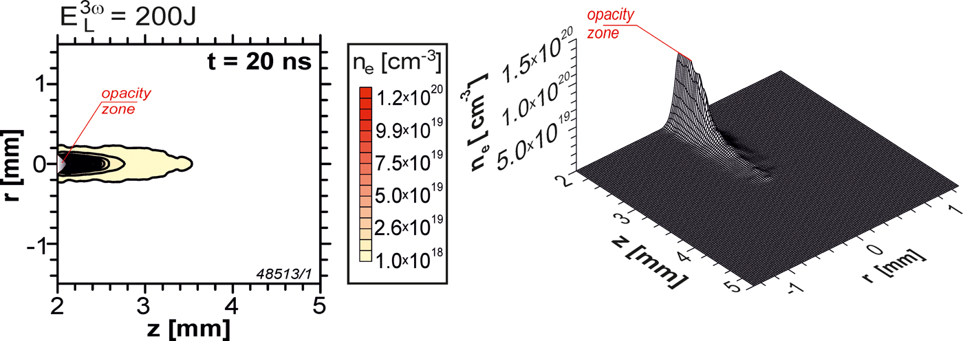
Fig. 2. The electron isodensitogram (left) and the space profile of electron distribution (right) for the plasma flowing out of the LICPA accelerator channel recorded 20 ns after the CH/Au target irradiation.
To determine the projectile velocity with the use of the streak camera, the method usually referred to as shock breakout chronometry (e.g. Cauble et al., Reference Cauble, Phillion, Hoover, Holmes, Kilkenny and Lee1993; Shui et al., Reference Shui, Chu, Zhu, He, Xi, Fan, Xin and Gu2016) was applied. For this measurements the LICPA accelerator channel outlet was closed by a 20 µm thick Al foil and the set of ion collectors was removed from the path between the accelerator and the camera (Fig. 1). We observed the light emission from the rear side of the foil which was imaged by an optical system on the entrance slit of the camera. The beginning of the emission occurred when the shock wave generated by the impact of the Au projectile into foil reached the foil rear surface. This shock breakout time (t sb) was measured with respect to the so-called fiducial: A portion of the main laser pulse with a known delay with respect to the time (t L) when the main pulse reaches the target in the accelerator cavity. A sample image of the impacted foil emission recorded by the camera and a temporal profile of the emission is shown in Figure 3. Based on the shock breakout time measurements the projectile velocity can be determined from the formula: v p ≈ βL acc/t acc, where L acc = L Ch, t acc = (t sb−t L)–(Δt p + Δt sb), and Δt sb is the time needed to pass the shock through the impacted foil. For the case presented in Figure 3, at β ≈ 1.36 and Δt sb ≈ 0.3 ns (estimation based on numerical simulations) we obtain v p ≈ 142 km/s.

Fig. 3. The streak camera image (a) and the temporal intensity profile (b) of the light emission from the rear surface of the Al foil impacted by the gold plasma projectile driven by LICPA. The time delay between the fiducial and the laser pulse irradiating the CH/Au target is equal to 32.7 ns. E L = 232 J.
For the determination of the projectile parameters with the TOF method, a set-up of nine ion charge collectors (ICs) located in the horizontal plane approximately symmetrically relative to the accelerator axis within the angle of 39o and at the distance of 31 cm from the accelerator was used (Fig. 4). From the TOF spectra recorded by the collectors we were able to determine various characteristics of the projectile plasma at long distance from the accelerator, in particular: The angular distribution of plasma (ion) velocity averaged over time, the mean plasma velocity v p defined as the ion velocity averaged over time and angle, the angular distribution of ion charge density, the spatial distribution of ion charge density for different times, and the total ion charge of plasma Q. In order to calculate v p, we first calculated the ion charge density q θ and the ion velocity averaged in time v θ in the θ direction (using the TOF spectrum recorded in the θ direction), and then v p was calculated from the formula: v p = ∑θv θq θ/∑θq θ. Having Q and v p and assuming that the projectile velocity is equal to the mean plasma velocity, the kinetic energy of the projectile can be calculated from the following formula: E p[J] ≈ 10−8(A/2Z)Qv p2, where A is the mass number of plasma ions, Z is the average charge state of plasma ions and Q and v p are in the SI units (C, m/s). The value of Z at the long distance from the accelerator (where ICs were located) could not be calculated from the TOF measurements, and we were able to estimate only the value Z out at the accelerator channel outlet based on the 2D PALE simulations where the average charge state of plasma ions was calculated from the QEOS equations (More et al., Reference More, Warren, Young and Zimmerman1988). However, due to the free expansion of the plasma in space between the accelerator and the ICs, the plasma is adiabatically cooled and the plasma ions have enough time (≥1 µs) to recombine before reaching ICs. As a consequence, the average charge state of ions reaching ICs can be significantly lower than Z out. Thus, having Q and v p from the TOF measurements and Z out from the simulations we can only determine a lower limit of the projectile kinetic energy and state that E p[J] > 10−8(A/2Z out)Qv p2. On the other hand, assuming the known mass of the accelerated plasma m p, the kinetic energy can be determined from E p = (1/2)m pv p2, so in the same way as in case of the measurements using interferometry or the streak camera. However, in case of using the ion diagnostic, v p is determined directly from measurements without the necessity to determine the factor β characterizing the run of the acceleration process in the accelerator.

Fig. 4. The TOF spectra of the plasma projectile driven by LICPA recorded by the ion collectors at a long distance (31 cm) from the CH/Au target. E L = 200 J.
Figure 4 presents sample TOF spectra of the projectile plasma recorded by ICs. In the presented case, almost all mass and kinetic energy of plasma are accumulated in the time period t ≤ 6 µs, and the plasma moves with the mean velocity v p ≈ 135 km/s.
Selected results of numerical simulations of the acceleration of the gold projectile in the LICPA scheme using the 2D PALE code are shown in Figure 5. The figure presents 2D spatial distributions of the kinetic energy and temperature of plasma in the LICPA accelerator in two stages of the projectile acceleration: When the main part of the projectile reaches the distance z = −1000 µm (Figs. 5a, b) and when the projectile is close to the channel outlet (z = −2000 µm, Figs. 5c, d). It can be seen that for both stages the projectile is a compact plasma object of the peak density >5 g/cm3, and almost all (~90%) kinetic energy and mass of the projectile is stored within a small z region of Δz < 100 µm (the plasma density distribution in this region, not shown here, is almost identical as the kinetic energy distribution). The temperature of gold plasma in the main, dense part of the projectile is relatively low and at the channel outlet its (averaged) value is about 50 eV and the average charge state of Au ions in the plasma (calculated from the QEOS equations) is approximately equal to Z out ≈ 10. However, due to the high projectile density, the pressure inside the projectile is high (~0.5 Mbar). As a result, when the projectile leaves the accelerator channel it not only moves along the z-axis but also expands in the radial direction, which is clearly visible in the TOF spectra (Fig. 4).

Fig. 5. 2D spatial profiles of kinetic energy density (a, c) and temperature (b, d) of plasma inside the LICPA accelerator channel at the moment when the gold projectile is in the middle of the channel length (z = −1000 µm) and when it begins to leave the channel (z = −2000 µm). The CH/Au target placed at the beginning of the channel (z = 0) is irradiated by the laser beam introduced into the accelerator cavity and directed along the channel axis (r = 0). E L = 200 J.
Table 1 summarizes the results of our measurements. It presents values of the mean velocity v p and the kinetic energy E p of the gold plasma projectile as well as the energetic acceleration efficiency η = E p/E L inferred from the measurements using different diagnostics. For the estimation of kinetic energy of the projectile from the measurements using interferometry, the streak camera and the ion diagnostic in case of estimation 1, we assumed the plasma projectile mass equal to 0.9 of the gold disc mass m d = 4.1 µg (this assumption was based on a detailed analysis of results of simulation of the projectile acceleration using the PALE code). However, for the last case, the projectile velocity v p was calculated from the ion diagnostic without any assumption on the coefficient β, while for the interferometry and the streak camera we assumed β = 1.36 ± 0.02 (see above). For the ion diagnostics, in case of estimation 2, the lower limit of the kinetic energy was calculated based on the formula E p[J] > 10−8(A/2Zout)Qv p2 with Z out ≈ 10 taken from the PALE simulations (see above). In this case, any assumptions were made on the projectile mass or β coefficient (Q and v p were determined directly from the ion diagnostics).
Table 1. The values of the mean velocity v p and the kinetic energy E p of the gold plasma projectile accelerated in the LICPA scheme or the AA scheme as well as the energetic acceleration efficiency η = E p/E L inferred from the measurements using different diagnostics

The table demonstrates fairly high similarity of the parameters of the LICPA-driven projectile obtained with quite different measurement instruments and methods of the parameters estimation – within the experimental errors the average values of these parameters are approximately the same. In particular, the projectile is accelerated to the velocity 140 km/s with the energetic acceleration efficiency of 15–19%. This acceleration efficiency is by more than factor 10 higher than the one obtained for the AA scheme (1.2%) which, in turn, is comparable with those achieved in many other experiments performed so far (Ozaki et al., Reference Ozaki, Sasatani, Kishida, Nakano, Miyanaga, Nagai, Nishihara, Norimatsu, Tanaka, Fujimoto, Wakabayashi, Hattori, Tange, Kondo, Yoshida, Kozu, Ishiguchi and Takenaka2001; Azechi et al., Reference Azechi, Sakaiya, Watari, Karasik, Saito, Ohtani, Takeda, Hosoda, Shiraga, Nakai, Shigemori, Fujioka, Murakami, Nagatomo, Johzaki, Gardner, Colombant, Bates, Velikovich, Aglitskiy, Weaver, Obenschain, Eliezer, Kodama, Norimatsu, Fujita, Mima and Kan2009; Karasik et al., Reference Karasik, Weaver, Aglitskiy, Watari, Arikawa, Sakaiya, Oh, Velikovich, Zalesak, Bates, Obenschain, Schmitt, Murakami and Azechi2010; Frantaduono et al., Reference Frantaduono, Smith, Boehly, Eggert, Braun and Collins2012; Shui et al., Reference Shui, Chu, Xin, Wu, Zhu, He, Xi and Gu2015, Reference Shui, Chu, Zhu, He, Xi, Fan, Xin and Gu2016).
Finally, we measured craters produced in the massive Al target by the impact of the gold plasma projectile accelerated in the LICPA and AA schemes by the 3 w, 200 J laser pulse. In both schemes the massive target was placed at the outlet of the cylindrical channel which in case of LICPA had the length of 2 mm and the diameter of 0.3 mm while for AA the channel diameter was equal to 2 mm (as previously) and the channel length was 0.4 mm, 1 mm or 2 mm. The volume of the crater produced by the projectile driven by LICPA was equal to 8.5 mm3, and was by a factor 25, 45 and 57 larger than the crater volumes obtained for the AA scheme with the channel length of 0.4 mm, 1 mm and 2 mm, respectively. Since the crater volume is proportional to the energy of the shock wave generated in the target by the projectile impact and the shock energy is higher for higher kinetic energy of the projectile, the observed big difference in dimensions of craters produced with the use of LICPA and AA is a clear indirect evidence that the kinetic energy of the projectile driven by LICPA is much higher than those of the projectile accelerated by AA.
Conclusions
In conclusion, the acceleration of the heavy plasma projectile in the LICPA accelerator has been investigated. It has been shown that in the accelerator with a 200-J laser driver a 4-μg gold plasma projectile can be accelerated to the velocity of 140 km/s with the energetic acceleration efficiency of 15–19% which is significantly higher than those achieved in the AA schemes and is the highest among the ones measured so far for any projectiles accelerated to the velocities ≥100 km/s. Such high acceleration efficiency coupled with the high density of the projectile driven by LICPA makes it possible to produce high-pressure shocks by the projectile impact much more efficiently than with the methods used so far (Badziak et al., Reference Badziak, Krousky, Kucharik and Liska2016). As a result, to create high-energy-density matter states, for example, for studies of the equation of state of various materials, much smaller and cheaper laser drivers could be used which would open the possibility to carry out such studies also in small laboratories.
Acknowledgements
This work was supported in part by the Ministry of Science and Higher Education, Poland under the grant no W39/7.PR/2015. Also, this work was supported in part by the European Union's Horizon 2020 research and innovation program under grand agreement number 633053. The experiment was performed within the Access to Research Infrastructure activity in the 7th Framework Programme of EU (Contract No. 284464, Laserlab Europe-III, project pals002015).


