


INTRODUCTION
The fundamental knowledge of the high charge state ion generation were obtained in the frame of the laser-plasma interaction research. In Russia, such investigations were carried out with different laser types. In particular, it was shown that high intensity laser radiation focused on material allows for the creation of high temperature powerful stream of plasma with small phase volume. The following separation of electron and ion components produces pulsed ion beam with superior luminosity. The schematic picture of a different laser-plasma interaction zones is shown in Figure 1. The region I is the critical density vicinity where the main part of the laser pulse is absorbed. In this region, the thermal conductivity is essential, so that the characteristic size D of this zone is more than the focal spot diameter d f. In the zone I, the plasma ionization state is maximal but ion transit time through the zone is less than ionization time, so stationary condition according to the electron temperature is not reached. In this case, the ionization prevails over the recombination. Particularly, this state is typical for CO2 laser plasma due to respectively low critical density. As regarding the electron temperature in the vicinity of a critical density, the maximal value increases within the increase of the wavelength for other fixed parameters. In the region II, the plasma temperature decreases due to an expansion, as a result, the recombination prevails over the ionization. For the case of CO2 laser plasma, the recombination goes slowly due to low plasma density but, as well, the number of particles is less. In the region III, plasma pressure becomes negligible to affect on an expansion dynamics, so the zone III is an inertial plasma drift region. Despite of low electron temperature, the recombination does not go up to the neutral atoms creation, but is stopped for the stationary state due to three-body recombination heating. They said the plasma ionization state is “frozen.” This phenomenon ensures the high charge state ion production for long drift length up to a few meters. Summarizing the data for different wavelength irradiations, one might say there are no crucial distinctions for the laser-plasma ion generators using different types of lasers.

Fig. 1. The general interaction zones in laser plasma.
Nevertheless, the CO2 lasers are mainly used in the practice due to their high output energy with comparative technical simplicity for the repetition rate configuration, low operation cost, and an appropriate technology. Listed below preferences of CO2 lasers ensure adapting them in a laser-plasma ion source for an ion accelerator injector. The use of such injectors in a heavy ion synchrotron simplifies the accelerator scheme due to momentary (by single pulse) ring filling by the particles of proper mass and charge state number.
Most of the investigations of the ion generation from CO2 laser-produced plasma and the laser-plasma generators development are made by ITEP-CERN-TRINITI collaboration (Sharkov & Scrivens Reference Sharkov and Scrivens2006; Makarov et al., Reference Makarov, Satov, Strel'tsov, Rerikh, Stepanov, Shamaev, Sharkov, Hazerot, Langbein and Cherveud1994; Reference Makarov, Nishchuk, Rerikh, Satov, Skobelev, Smakovskii, Starostin, Stepanov, Pikuz, Faenov and Khomenko2000; Kozochkin et al., Reference Kozochkin, Makarov, Satov, Strel'tsov, Rerikh, Starostin, Stepanov, Shamaev, Sharkov, Haseroth, Langbein, Sellmair and Sherwood1994; Kondrashev et al. Reference Kondrashev, Mescheryakov, Sharkov, Shumshurov, Khomenko, Makarov, Satov and Smakovskii1994, Reference Kondrashev, Collier and Sherwood1999; Baranov et al., Reference Baranov, Makarov, Roerich, Satov, Starostin, Stepanov, Sharkov, Langbein and Sherwood1996; Stepanov et al., Reference Stepanov, Volkov, Zaitsev, Makarov, Satov and Rerikh2003a, Reference Stepanov, Satov, Makarov, Roerich, Smakovskiy, Maluta and Starostin2003b, Satov et al., Reference Satov, Sharkov, Smakovski, Makarov, Stepanov, Roerich, Kondrashev, Shumshurov and Balabaev2004a, Reference Satov, Makarov, Stepanov, Roerich and Smakovski2004b, Reference Satov, Sharkov, Haseroth, Smakovski, Makarov, Kondrashev, Roerich, Stepanov, Kugler, Scrivens, Camut, Shumshurov, Balabaev and Charushin2004c, 2008, Mescheryakov et al., Reference Mescheryakov, Alexeev, Balabaev, Kondrashev, Konyukov, Nikolaev, Roudskoy, Savin, Sharkov and Shumshurov2002; Collier et al., Reference Collier, Hall, Haseroth, Kugler, Kuttenberger, Langbein, Scrivens, Sherwood, Tambini, Sharkov, Shumshurov and Masek1996; Haseroth & Hora, Reference Haseroth and Hora1996; Barabash et al. Reference Barabash, Koshkarev, Lapitskii, Latyshev, Shumshurov, Bykovskii, Golubev, Kosyrev, Krechet, Haydarov and Sharkov1984) as well as in other laboratories (Boody et al., Reference Boody, Höpfl, Hora and Kelly1996; Ogawa et al., Reference Ogawa, Yoshida, Nakajima, Hasegawa, Fukata, Horioka and Oguri2003). Applications of CO2 laser-plasma generator of multicharge ions in working accelerators were realized in Dubna (JINR Russia) (Monchinsky et al., Reference Monchinsky, Kalagin and Govorov1996) and GSI (Germany) (Dubenkov et al., Reference Dubenkov, Sharkov, Golubev, Shumshurov, Shamaev, Roudskoy, Streltsov, Satov, Makarov, Smakovsky, Hoffmann, Laux, Müller, Spädtke, Stöckl, Wolf and Jacoby1996). It was shown in the frame of lead ion generation measurements with a target power density q up to q ≃ 5 × 10¹³ W/cm2: (1) The total number of ions is proportional to the laser pulse energy for equal other parameters; (2) The average ion charge state number is proportional to the laser flux at a target, at least, for the case of ionization of external atoms shells; (3) It is necessary to use the laser pulse duration τp less than the characteristic plasma expansion time τexp (τp ≤ τexp). The latter is defined by the ion velocity and the characteristic plasma thickness, which depend finally on target laser pulse power density (for fixed wavelength) and, slightly, on the target material atomic number. Otherwise (τp > τexp), the process of laser-plasma interaction is complicated because of refraction of some part of the laser pulse in the plasma corona, self-focusing of the laser radiation, and creation of series of shock waves, which distorts the plasma flow. As a result, the laser heating efficiency drops and useful part of ions near expansion axis is decreased.
Thus, there are two useful practical conclusions. First, the increase of particle number for definite charge state is ineffective with the increase of laser pulse duration with the constant power density. To make it is necessary to increase the focal size for the fixed laser power density at the target. Second, to achieve higher charge state number of ions one should not only increase the radiation power density at the target but apply respectively shorter laser pulse.
The data obtained ensure to choose the laser driver scheme under some common features. It is known, for example, that free-running CO2 generator provides the laser pulses with the duration τp ≥ 40 ns. That allows to efficiently use such a laser in the ion generation application up to q ≃ 1012 W/cm2 and, respectively, for the plasma expansion velocity V exp ≃ 106 cm/s, so that should not be essential plasma expansion while the laser heating (V exp × τp ≤ ≃0.4 mm). The ion generation for higher laser flux has to use more complicate optical laser scheme such as master-oscillator power amplifier (MOPA) configuration. The shortest probable pulse duration in this case is τp ≃ 150 ps with accordance to the amplification line width of 7 GHz for the typical gas mixture of an atmospheric pressure CO2 laser (Abrams, Reference Abrams1974).
The ITEP heavy ion accelerator injector based on both the free-running and the MOPA CO2 lasers. The laser-plasma ion source with the MOPA principle is directed to generate extremely ionized heavy particles, similar to Fe, Ag, Pb, etc. (Sharkov et al., Reference Sharkov, Alexeev, Alekseev, Balabaev, Nikolaev, Satov, Schegolev, Shumshurov and Zavodov2008; Satov et al., Reference Satov, Sharkov, Haseroth, Smakovski, Makarov, Kondrashev, Roerich, Stepanov, Kugler, Scrivens, Camut, Shumshurov, Balabaev and Charushin2004c). The free-running CO2 laser is used for the creation of C3+– C4+ ion beam with laser target power density of ≃1011 W/cm2 in the frame of ITEP scientific programm of fundamental researches and medical applications. The experimental results devoted to the development of this laser are presented in this paper.
GROUNDS FOR INCREASE OF SPECIFIC OUTPUT LASER POWER
Effectiveness of the CO2 free-running laser in the ion injectors application is defined, mainly, by a possibility of high intensity generation. That rises with the decrease of the first spike duration of the laser pulse and the increase of its energy content. A typical temporal low intensity “tail” for the CO2-laser generation does not act upon the fraction of high-charged ion but creates a great number of low-charged particles and neutral atoms. It results in undesirable effects such as the coating of the optical elements, the deteriorating of the vacuum condition, the additional load of the accelerator etc.
One should distinguish two setups for the CO2 laser. The first configuration is aimed to the gain of the total illumination energy and is often cited as a laser efficiency parameter. The second one provides the maximal peak power. Conditions for these laser schemes are differed for both an electrical discharge pumping and a resonator quality. Really, the first spike generation is defined by the population evolution of the rotation-vibration levels of CO2-molecule, i.e., by the gain coefficient behavior during first tens of nanoseconds. So, the population of N2 does practically not affect on the rising of the laser intensity because of the long (a few microseconds) time of the vibration excitation transmission for N2 → CO2 process. At the same time, the total stored energy and, finally, the laser pulse energy depends strictly on the fraction of nitrogen, its vibrational levels excitation, and the pumping duration. The optimal ratio of the partial pressure of dioxide of carbon and nitrogen p(CO2)/p(N2) is about 0.5 in this case (Baranov et al., Reference Baranov, Borisov, Napartovich, Napartovich and Satov1976a; Manes & Sequin, Reference Manes and Seguin1972). At the same time, this ratio optimized for pick power generation or maximal gain coefficient creation, lies into the interval 2–4 (Lachambre et al., Reference Lachambre, Gilbert, Rheault, Fortin and Blanchard1973). The optimal laser resonator quality is quite different for these two laser configurations. While the maximal energy setup requires high Q and, respectively, low generation threshold. The minimal value of the threshold is defined by only intra-resonator energy dissipation due to losses (collision relaxation, light scattering, and absorption, etc) that is low enough. In contrast, the powerful generation is realized for high generation threshold like the generation of the giant pulse in Q-switched lasers. The important additional distinction is an energy deposition rate. The deposition of total electrical energy into discharge is a general parameter for the first laser setup, for the second one it is more important a discharge power while the first phase of lasing. As the investigations have shown (Sharkov et al., Reference Sharkov, Alexeev, Alekseev, Balabaev, Nikolaev, Satov, Schegolev, Shumshurov and Zavodov2008; Satov, Reference Satov2006), the next discharge circuit parameters are close to optimal in case of high-power laser pulse generation: “shock” capacitance of the pulsed voltage generator — 60–75 nF on the one meter length at the square discharge profile; idling voltage of the electric generator is to create field of E = 25–27 kV/cm for the atmospheric discharge pressure at the optimal mixture (CO2/N2/He = 4/1/5). It has been mentioned that the small signal gain coefficient reaches for value of 4·10−2 cm−1 under these conditions.
Anyway, the development of CO2 laser is based first of all on improvement of self-sustained uniform discharge characteristics in atmospheric pressure gas mixture. It is known (Osipov, Reference Osipov2000; Satov, Reference Satov2006), the determinative factors defined self-sustained uniform discharge formation are the following: (1) preionization, which might exceed some threshold value: the initial electron density can be varied from 104–105 up to 1010–1011 cm−3 for different discharge system; (2) value and rising time of the voltage pulse, which must have an optimal values: in particular, applied voltage (idling voltage of electrical generator) must exceed stationary breakdown voltage significantly; (3) level of an electrical deposition energy or power, which must not exceed a critical value for given conditions to avoid the discharge contraction; (4) electrode profile, which plays an essential role at both the breakdown stage and the forming volume period of self-sustained discharge, assisting or preventing the instability increase.
IMPROVEMENTS OF LASER GENERATOR
Among a variety of designs to form a uniform volume discharge the widely used ones are the systems with an auxiliary capacitor (so-called “peaking” capacitorFootnote 1). One of the technically successful circuit designs with the use of the auxiliary capacitor has been published (Burnett et al., Reference Burnett and Offenberger1973) and, independently in Baranov et al. (Reference Baranov, Borisov, Napartovich, Napartovich and Satov1976a). In this design, the auxiliary capacitors having much less values than the main one were installed with a small inductance at the side of the discharge electrodes and attached by the discharge gaps. The spark discharge that was generated during the auxiliary capacitors charging created the UV-preionization of the discharge volume. While the main capacitor is recharged through the constructive inductance to the auxiliary capacitor, the voltage of the last one is doubled and the discharge current is peaked on the initial stage of the discharge. The last circumstance stabilizes the uniform phase of the self-sustained discharge and thus allows one to improve the output characteristics of the laser (Satov, Reference Satov2006; Feoktistov et al., Reference Feoktistov, Charushin, Louzhnov, Roerikh, Satov, Shchepetov, Smakovskii, Starodub, Stepanov and Zaretskii2002). As it was shown by investigations, the laser generators based on this principle have high specific characteristics. The same schematic diagram (see Fig. 2) was used for the laser generator “Malish” (ITEP) that is a part of the C+3 ÷ C+4 ions injector.

Fig. 2. The schematic diagram of the discharge circuit with a “peaking” capacitor: R1 = the commutator resistance, R2 = spark gaps resistance, RP = discharge resistance, C1 = main charging capacitor, C2 = “peaking” capacitor, L1, L2 = construction inductance.
It is possible, however, a further improvement of the CO2-laser specific characteristics, based on the growth of the energy input to the uniform discharge and rise of the molecular gases content in the active mixture of the laser. One of such methods is described in Satov et al. (Reference Satov, Smakovskii and Khomenko1997). The concept is to try to separate the stages of the discharge volume ionization and the energy input to the discharge similar to the non-self-maintained discharge. To do this profiled voltage pulse is formed on the discharge electrodes simultaneously with UV-illumination of the gas volume. That is provided by introduction of additional “shock” LC-circuit (C 2L 2C 3) to the power supply circuitry as it is shown in Figure 3. The second circuit has to be triggered at the moment of C 2 capacitor was recharged (after a quarter of oscillation period in the first circuit). The moment of the circuit commutation is adjusted by an appropriate delay in the R 3 discharger. The circuit scheme allows us to form a “quadruple” amplitude (in comparison to the C1 charging voltage) short voltage pulse and, correspondingly, a powerful peak at the beginning of discharge current. On this stage, the energy input to the discharge is not high and is aimed at increase of the initial concentration of electrons generated by UV-illumination, and at formation of the uniform volume phase of the discharge. The major pumping of the laser active medium occurs on the second stage of the discharge at significantly lower values of E/p, what increases the efficiency of the excitation of the CO2 vibrational-rotational levels. Such a basic circuit was applied in this work for upgrading of the CO2-generator “Malish” to increase the laser power and to improve the temporal shape of the laser pulse. The functioning of discharge excitation circuit can be analyzed using of a uniform model similar to the model used in Baranov et al. (Reference Baranov, Borisov, Napartovich, Napartovich, Satov and Sudakov1976b), where the discharge resistance is described by the equation with account of ionization and recombination processes. This model does not take into account the initial inhomogeneities of the electronic concentration as well as the processes that lead to destruction of this uniformity during the discharge. The following calculations were performed using the code described in Feoktistov et al. (Reference Feoktistov, Charushin, Louzhnov, Roerikh, Satov, Shchepetov, Smakovskii, Starodub, Stepanov and Zaretskii2002).
The discharge gap resistance was found as solution of equation
where βe is the effective rate of the electronic recombination, μe = 0.42 × 10⁶/p is the electrons' mobility (Raizer, Reference Raizer1997), z = αv d is the effective ionization rate, v d = μeE is the electrons' drift velocity. The dependence of the ionization coefficient α on |E/p| was calculated using the empirical Townsend formula (|E/p| > 30)
where the values of parameters A = 8.8 and B = 275 were taken from Raizer, (Reference Raizer1997) for pure nitrogen. In the range of small values |E/p| < 30, we use the equation
(where A 1 = 3.3 × 10⁻⁷, B 1 = 0.265) that gives a small but finite value of α for small |E/p|. This allows us to avoid problems on the initial stage of numerical solution. There is no influence of this part of α(|E/p|) dependence on the course of solution for physically significant values of E and, accordingly, values of the discharge current. The recombination rate β has a weak dependence on E/p in the range of interest for this parameter (Bardsley, Reference Bardsley, Biondi, Bates and Esterman1970). We used the value β = 10−7 (Raizer, Reference Raizer1997; Ernst & Boer, Reference Ernst and Boer1980). Eq. (1) coupled with the Kirchhoff laws was solved numerically for circuits shown in Figures 2 and 3.

Fig. 3. Schematic diagram with additional LC-circuit: R1 = the commutator resistance, R2 = spark gaps resistance, RP = discharge resistance, C1 = main charging capacitor, C2, C3 = additional capacitors, L1, L2, L3 = construction inductance of circuitries.
In Figures 4 and 5, the results of calculations for the circuits of the discharge module “Malish” and the redesigned laser are respectively shown. The main commutator is the high pressure gas spark gap with the rise-time of ~50 ns and is described in the simulation as an exponential decay of the resistance. For the other commutators, the resistance dependence and the breakdown delays at some threshold gap voltage are specified similarly. Note that the calculation results as well as the laser characteristics given below correspond to conditions of stable work of the modules in a long-term regime with repetition rate ~0.5 Hz. As it can be observed (Fig. 4), the less-inductive capacitor with a small face-value being installed in parallel to the discharge allows us to increase the pulse voltage applied to the discharge electrodes and to form a pulse of current with a sharp front during the initial stage of the process. This promotes stabilization of the volume characteristics of the discharge. The system provides a possibility to form a stable discharge in the mixture CO2/N2/He = 1/1/8 at the atmospheric pressure with a deposition energy of ~150 J/l.

Fig. 4. The simulation results for the transient process in the circuit of the discharge module “Malish” at V0 = −38 kV, C1 = 50 nF, C2 = 6.6 nF, L1 = 270 nH, L2 = 50 nH (a) voltages on the discharge, on the main and the ‘peaking’ capacitors; (b) discharge current; (c) the discharge resistance (left) and the electrical power input to the discharge (right).

Fig. 5. The simulation results for electrical characteristics of the discharge module “Malish-M” at V0 = −70 kV, C1 = 50 nF, C2 = 1.65 nF, C3 = 0.8 nF, L1 = 300 nH, L2 = 50 nH, L3 = 20 nH (a) voltage on capacitors C1, C3 and on the discharge; (b) the discharge current; (c) the discharge resistance (left) and the electrical power input to the discharge (right).
The introduction of the second circuit (C2–L2–C3) allows one to form a profiled voltage pulse that splits the discharge process in two characteristic stages. On the first stage, when the discharge voltage Vp (Fig. 5a) grows up to a significant value, the effective ionization of the discharge volume occurs. Though the energy input on this stage is not higher than 10%, the discharge resistance drops to a few Ohms. The discharging of the main part of the stored energy occurs then at the field strength values that are more close to optimal ones for the laser pumping. It is important that during the discharge process the plasma resistance is close to the impedance-matched regime ![]() . This fact as well as the absence of high-frequency components (sharp fronts and HF-oscillations) on temporal profiles of the discharge characteristics contribute to stability of the uniform stage of the discharge. The experiments have shown that this circuit allows us to form a volume discharge in the mixture CO2/N2/He with enlarged content of molecular gases for a twice higher value of the specific deposition energy (~310 J/l) and in a larger volume than it was observed for the previous set. To provide the optimal values of the output parameters of the pulsed voltage generator and to reduce the charging voltage, we used the two-stage Arkad'ev-Marx generator as the main capacitor C1 with an equivalent “shock” capacitor of 50 nF and idling voltage ~70 kV. One of the critical parameters of the discharge excitation circuit is the overall inductance that should be reduced as possible. For this reason, the construction of the pulsed voltage generator assumed minimization of the total circuit inductance. This was provided by appropriate positioning of the elements and by using of less-inductive capacitors IKCh-50-0.1 (with self-inductance value of L0 ≈ 12 nH) and less-inductive commutators. As the last ones we used the nitrogen spark gaps with field distortion triggering.
. This fact as well as the absence of high-frequency components (sharp fronts and HF-oscillations) on temporal profiles of the discharge characteristics contribute to stability of the uniform stage of the discharge. The experiments have shown that this circuit allows us to form a volume discharge in the mixture CO2/N2/He with enlarged content of molecular gases for a twice higher value of the specific deposition energy (~310 J/l) and in a larger volume than it was observed for the previous set. To provide the optimal values of the output parameters of the pulsed voltage generator and to reduce the charging voltage, we used the two-stage Arkad'ev-Marx generator as the main capacitor C1 with an equivalent “shock” capacitor of 50 nF and idling voltage ~70 kV. One of the critical parameters of the discharge excitation circuit is the overall inductance that should be reduced as possible. For this reason, the construction of the pulsed voltage generator assumed minimization of the total circuit inductance. This was provided by appropriate positioning of the elements and by using of less-inductive capacitors IKCh-50-0.1 (with self-inductance value of L0 ≈ 12 nH) and less-inductive commutators. As the last ones we used the nitrogen spark gaps with field distortion triggering.
LASER CHARACTERISTICS OF THE GENERATOR “MALISH-M” AND APPLICATION IN SYNCHROTRON INJECTOR
Output parameters of a high voltage pulse generator were measured by current monitor through the resistor load. Dependency of laser pulse intensity on time was reconstructed by using of the laser oscilloscope traces and value of the total pulse energy. The photon-drag detector PhD-2 was used in a collaboration with calorimeters: SCIENTECH 378, ED-50-02, and PIP 100-MK. For the data, proceeding digital oscilloscope with bandwidth of 20 MG and software were used. High voltage behavior on the capacitor C2 (see Fig. 3) and the laser intensity are shown in Figure 6. It should be known, the time resolution of laser pulse measurement was not enough to solve fine mode locking structure, so laser intensity in Figure 6 is averaged during laser pulse.

Fig. 6. The signals of absolute value of high voltage on C2 (a) and laser intensity for the laser “Malish-M” (b).
Time scale starts from the HV-generator trigger pulse in this figure. Technical parameters and output characteristics of “Malish” and “Malish-M” lasers are gathered in Table 1. The most important for the application in laser-plasma generator result is a significant (five times) increase of laser radiation power. This achievement is based on increase of discharge specific deposition energy and use more optimal gas mixture for laser out. It should be noted, the reached level of specific laser pulse power of 105 J/l is the highest among known literature references for repetition rate CO2 laser operating in long-term mode. Laser pulse radiation power behavior during first operation time interval in repetition rate of 0.3 Hz is approximated by a function I(t) = 8.6·exp(−t/15) + 53, where I(t) is measured in MW, t is in minutes. One can see the output laser pulse power slightly decreases during several minutes operation and reaches a stable level of 53 MW that remains valid for about 500 hours without intervention.
Table 1. Main parameters of lasers

Far field of the laser intensity of “Malish-M” is studied with registration of the focal plane distribution of the beam. Toward this end the laser beam is focused with a spherical mirror at the distance of 13 m from generator outlet and spatial energy density distribution is detected by means of IR camera PYROCAM III (resolution of 0.1 × 0.1 mm). 3D spatial shape of the focal spot is shown in Figure 7 for the objective focal length F = 700 cm. Data processing indicates the central part of the beam is close to Gaussian form and contains near 55% of the total energy. Corresponding angular distribution of the laser beam intensity is presented in Figure 8: divergency can be estimated as 3.7 × 10⁻⁴ for intensity level of 1/e. Measured spatial shape is in good agreement with a presentation of generator output beam as a result of propagation of a plane uniform wave through the ring aperture D = 30 mm, d = 11 mm in accordance with the laser generator unstable confocal resonator dimensions. Calculations of the laser beam spatial distribution were made with software FOCUSD using a code for diffraction propagation of radiation under condition of cylindrical symmetry taking into account real apertures of optical elements (Satov et al., Reference Satov, Sharkov, Haseroth, Smakovski, Makarov, Kondrashev, Roerich, Stepanov, Kugler, Scrivens, Camut, Shumshurov, Balabaev and Charushin2004c).

Fig. 7. Distribution of laser energy density on the focal plane of objective with F = 700 cm.

Fig. 8. Calculated (a) and measured (b) angular distribution of the “Malish-M” laser beam energy density.
An optical scheme ensures to transport the laser beam of “Malish-M” up to focusing mirror objective using amount of plain mirrors and beam expander with multiplication M = 4.2. Calculation results of the laser beam spatial distribution are shown in Figure 9 for different points of the optical scheme. Spatial losses of the laser beam in real apertures of optical elements are estimated as 10%. The calculation does not take into account reflectance losses so these characteristics were obtained experimentally and come to ≃30% for nine copper mirrors. Finally, the focal laser target flux is derived as q ≃ 6 × 10¹¹ W/cm2 in view of the radiation pulse duration of 40 ns. Synchrotron injector scheme based on laser-plasma ion generator is shown in Figure 10. After the target heating plasma jet comes up to HV extraction system where separation of charges occurs and ion beam is created. After low energy transport line consisted of three electrostatic lenses ion beam comes in a buncher operated for frequency 2.5 MHz and, then, to resonance two-gap accelerator I-3. Analyzing magnet is situated at the injector outlet so particles beam of C4+ is formed finally with the energy of 16 MeV and the total current about 6 mA (Fig. 11). The typical repetition rate of injector cycles is 0.3 Hz.

Fig. 9. Calculated spatial distributions of laser beam for different elements of the optical scheme. (a) at the expander input; (b) at the expander output; (c) at the focusing mirror; (d) on the focal plane of an objective with aperture F/8, z is a distance from the laser output. Left–linear scale, right–logarithmic scale.

Fig. 10. ITEP heavy ion injector scheme based on laser-plasma generator.
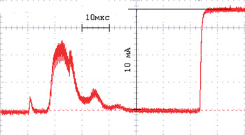
Fig. 11. (Color online) Current signal of C4+ ions at the injector outlet.
SUMMARY
As a results of this work one might conclude the following: (1) The electrical scheme for the uniform discharge creation was developed due to the self-consistent formation of the time-profiling pulse applied for the discharge electrodes. The improvement allows to raise up a reliability of the discharge module and increase significantly electrical energy deposition. (2) The physical model and the numerical code were worked out to describe the uniform discharge characteristics and optimize the electrical scheme parameters. (3) The output laser intensity was increased by a factor of five for the complete free-running generator for the same overall size. (4) The ion current of C4+ particles was obtained at outlet of ITEP ion injector based on described laser generator for long term operation with repetition rate of 1Hz.
ACKNOWLEDGEMENTS
The work was completed in the frame of project #H.4e.45.03.09.1086, with support from the RFFI project 07-02-13602 and grant NSh-3239.2010.2.
Authors thank I. Khrisanov for help with the PYROCAM III measurements.


