


Introduction
Nowadays, RF ion sources, especially helicon ion sources, are used for various applications. These applications consist of material processing (Li et al., Reference Li, Bulla, Charles, Boswell, Love and Luther-Davies2002, Reference Li, Boswell, Samoc, Samoc and Wang2008), ion implantation (Tanjyo et al., Reference Tanjyo, Sakai and Takahashi2001), plasma thrusters such as helicon double-layer thruster (Charles et al., Reference Charles, Boswell and Lieberman2006), focused ion beam accelerators (Voznyi et al., Reference Voznyi, Miroshnichenko, Mordyk, Shulha, Storizhko and Tokman2013), neutron generators (Verbekea et al., Reference Verbekea, Leungb and Vujica2000; Jung et al., Reference Jung, Park, Kim and Hwang2004), ion beam injection for fusion (Sonato et al., Reference Sonato, Agostinetti, Bolzonella, Cismondi, Fantz, Fassina, Franke, Furno, Hopf, Jenkins, Sartori, Tran, Varje, Vincenzi and Zanotto2017), nuclear microscopy (Mordyk et al., Reference Mordyk, Miroshnichenko, Nahornyy, Nahornyy, Shulha, Storizhko and Voznyy2006), etc. Ion implantation is a low-temperature surface modification process in which ions are injected into the near-surface region of a substrate. High-energy ions, typically with 10–200 keV energy, are produced in an accelerator and directed as a beam onto the substrate surface (Wei et al., Reference Wei, Xu and Wang2009; Verdian, Reference Verdian2017). It has been widely used in surface finishing (Fang et al., Reference Fang, Chen, Zhang, Hu and Zhang2011), ion implantation-induced nanoparticle formation (Popok, Reference Popok2012), and semiconductor industry such as doping (Zhou et al., Reference Zhou, Yu, Han, Cheng, Chen and Zhu2008), Mesotaxy (Sjoreen et al., Reference Sjoreen, Jebasinski, Schmidt and Mantl1992), etc. The important merits of a helicon ion source are relatively high operational life, fairly small size of device, high ionization, and low emittance (Mordyk et al., Reference Mordyk, Miroshnichenko, Shulha and Storizhko2008).
The Amirkabir Helicon Ion Source (AHIS) can be divided into two important parts. In the first part of the device, the helicon plasma is generated (Soltani and Habibi, Reference Soltani and Habibi2017), and in the second, the ion beam is extracted (Afsharmanesh and Habibi, Reference Afsharmanesh and Habibi2018). This source was equipped to a diode extraction system and a half-helix antenna is used to excite the helicon wave into the plasma volume. We are going to design and simulate a triode extraction system for AHIS for ion implantation in this paper.
There are a lot of commercial codes used for simulation of extraction systems such as IGUN (Becker and Herrmannsfeldt, Reference Becker and Herrmannsfeldt1992; Reijonen, Reference Reijonen2007), PBGUN (Sutherland et al., Reference Sutherland, Keller, Irzyk and Boswell2004), LORENTS (Asi, Reference Asi2002), SIMION (Park and Kim, Reference Park and Kim2017), and KOBRA (Wutte et al., Reference Wutte, Leitner, Lyneis, Taylor and Xie1999) in which simulation methods lead to difference among them.
Of course, the plasma modeling is not considered in SIMION and LORENTS codes and this is the cause of difference between them and the other codes. In addition, another important difference among them is the capability of exact calculation of space charge. Both IGUN and PBGUN codes are merely used for plasma modeling in two dimensions (2D) (Kalvas, Reference Kalvas2013). IBSimu is an ion optical computer simulation package utilized for design and improvement of the negative and positive ion source extraction systems. This code, which is used via C++ programming language, has significant advantages which include definition of electrode geometry and calculation of electric fields in 1D, 2D, 3D, and in cylindrically symmetric geometry and calculation of pulsed particle trajectory in electric and magnetic fields.
Triode extraction systems are simulated in helicon plasma with the IBSimu code for the first time in this paper (Kalvas et al., Reference Kalvas, Tarvainen, Ropponen, Steczkiewicz, Ärje and Clark2010; Kalvas, Reference Kalvas2013). Design of two extraction systems for generation of H− beam of the Linac4 (linear accelerator) ion source for improvement of the Cern accelerator complex by using of IBSimu code was implemented (Midttun et al., Reference Midttun, Kalvas, Kronberger, Lettry, Pereira, Schmitzer and Scrivens2012; Midttun, Reference Midttun2014). IBSimu code also has been used for simulation of double einzel lens extraction system of the 14 GHz ECR ion source which was built for Accelerator Laboratory in the Department of Physics (JYFL), University of Jyväskylä (Toivanen et al., Reference Toivanen, Kalvas, Koivisto, Komppula and Tarvainen2013). It can be concluded from the similarity between the simulation results and experimental outcomes that IBSimu code has an appropriate operation in this system simulation. IBSimu code has been employed for thermal modeling of RF gridded ion thruster (Dobkevicius and Feili, Reference Dobkevicius and Feili2016). IBSimu code was used to simulate ion extraction from a RF plasma source for determining the available relation between sheath edge and T e, n e; IBSimu code was used to simulate ion extraction from a RF plasma source (Ke and Zhou, Reference Ke and Zhou2014). IBSimu code was utilized for simulation of extraction system and Wien filter in a hydrogen plasma discharge (Cortázar et al., Reference Cortázar, Megía-Macías, Tarvainen, Kalvas and Koivisto2016). Formation of GTS-LHC (Grenoble Test Source-Large Hadron Collider) ECR ion source beam with xenon, argon, and lead in variable beam extraction conditions was investigated by using of IBSimu code (Toivanen and Küchler, Reference Toivanen and Küchler2016). The IBSimu code was used for studying the space charge compensation in a 45 keV H− unbunched beam of a Linac4 ion source with residual gas (Valerio-Lizarraga et al., Reference Valerio-Lizarraga, Leon-Monzon and Scrivens2015). Finally, IBSimu has been utilized for modeling of H− ion source extraction system from a spallation neutron source (Kalvas et al., Reference Kalvas, Welton, Tarvainen, Han and Stockli2012).
This new research was carried out to:
(1) Study the triode extraction systems for helicon ion source and their simulation, by IBSimu code.
(2) Optimization of Ө1 and Ө2 degrees in pierce electrode for the first time in helicon plasma.
(3) Introducing the “Khoshhal electrode” as a new parabolic plasma electrode (PE) and presentation of its equation with optimized indices for application in ion implantation.
(4) Determining the optimized gap distance and extraction voltage for pierce and parabolic geometries.
(5) Investigating the effects of ion temperature and parabolic PE aperture diameter in beam optical characteristics.
This paper outlines the design considerations in section “Design considerations: theoretical background”. Simulation and design processes will be discussed in section “Simulation process of three types of triode extraction system”. Simulation results will be mentioned in section “Results and discussion”. Finally, our results have been concluded in section “Conclusions”.
Design considerations: theoretical background
One important parameter among the beam optical characteristics is the beam emittance. Beam emittance can be controlled by the aperture radius of PE and ion temperature, but controlling the ion temperature within plasma is more difficult. Therefore, it can be inferred that beam emittance has a direct relation with aperture radius and for having an optimized ion beam, emittance should be as small as possible. The emittance based on thermal energy is given by (Leitner et a l., Reference Leitner, Wutte and Lyneis2001).
 $${\rm \varepsilon} _{{\rm r}{\rm. m}{\rm. s}{\rm.}} = 0.016r\sqrt {\displaystyle{{KT_{\rm i}} \over {M_{\rm i}/q}}}. $$
Although low-aberration ion beam distributions often have roughly elliptical contours, it is a simple solution to use ellipse as calculation model in the 2D phase space. Differential equation for an origin-centered ellipse is given by Kalvas (Reference Kalvas2013)
 $${\rm \epsilon} = {\rm \gamma} x^{\rm 2} + {\rm 2}{\rm \alpha} xx^{\prime} + {\rm \beta} x^{\prime \rm 2}.$$
In this equation, ϵ is the 2D transverse emittance and α, β, and γ are the Twiss parameters used for description of the emittance ellipse. The most important dimensions of the emittance ellipse geometry are shown in Figure 1.
 $${\rm \alpha} = \displaystyle{{-\langle xx^{\prime}\rangle} \over {\rm \varepsilon}}, {\rm \beta} = \displaystyle{{-\langle x^2\rangle} \over {\rm \varepsilon}}, \;{\rm and}\;{\rm \gamma} = \displaystyle{{-\langle x^{\prime 2\rangle}} \over {\rm \varepsilon}}. $$
Fig. 1. Geometry of emittance ellipse with the most important dimensions.
The ellipse area is defined as Kalvas (Reference Kalvas2013)
 $$A = {\rm \pi \epsilon} = {\rm \pi} R_{\rm 1}R_{\rm 2}.$$
 In which,  $R_{\rm 1} = \sqrt {{\rm \varepsilon} /2} (\sqrt {H + 1} + \sqrt {H-1} )$ and
  $R_{\rm 2} = \sqrt {{\rm \varepsilon} /2} (\sqrt {H + 1} -\sqrt {H-1} )$. R 1, R 2 are known as major and minor radius of the ellipse, respectively. Also, H is (α + β)/2.
Simulation process of three types of triode extraction system
Triode geometry is composed of three different electrodes. The first electrode, known as “PE”, plays an important role in operation of the triode extraction system and especially on its beam optical characteristics. The plasma surface is terminated by this electrode in the discharge boundary. The main function of plasma electrode is determining the shape and the size of emission aperture and also to specifying the plasma meniscus circumference; because the shape of this aperture plays a key role for having a focused ion beam. The second electrode, called “extraction electrode” (EE), is in negative potential than the plasma for positive ion sources and can generate ion optical trajectories. But, the beam efficiency is not too sensitive to the shape of EE. The third electrode, called “ground electrode” (GE), which is at ground potential, is often used to terminate electric fields leading to beam space charge neutralization. The ions, at first, are accelerated and then their velocity decreases at the ground potential.
Three extraction geometries are designed and simulated by IBSimu code in this part of the paper. It should be noted that EE and GE have an unvaried special design in each of these three geometries. Repetition of EE and GE geometries in simulation of each three extraction systems helps to better compare the effect of plasma electrodes in beam optical characteristics. In the first triode system, as shown in Figure 2, an ordinary electrode with a primary design is used as plasma electrode (Zhang, Reference Zhang1999). Thus, it can be considered as a basis for perfect comparison of the operational results of the other geometries.
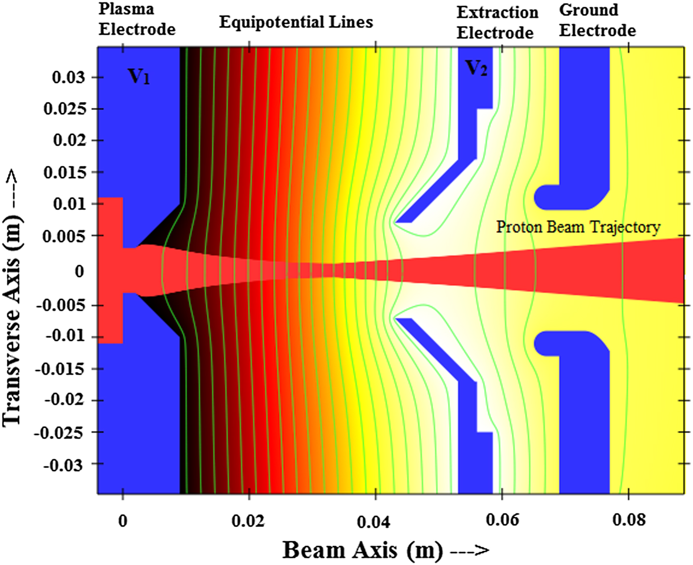
Fig. 2. Ordinary geometry and proton beam trajectory simulation in the IBSimu code at 66 kV extraction voltage (the number of iterations is 15, mesh size is 0.05 mm, and gap distance is 37 mm).
A cylindrical pyrex tube that has an outer diameter of 2.5 cm and a length of 43 cm is used as the Amirkabir Helicon Plasma Source (AHPS) chamber. RF power is delivered by using a half-helix antenna at 13.56 MHz frequency. Maximum plasma density in AHPS occurs around 380G, with values of 1 × 10¹⁸–1 × 10¹⁹ m−3 for the magneto-static field with 1 kW RF power (Soltani and Habibi, Reference Soltani and Habibi2017; Afsharmanesh and Habibi, Reference Afsharmanesh and Habibi2018). Some characteristics and initial imposed conditions for each triode systems are represented in Table 1.
Table 1. Main parameters in IBSimu simulations

The same initial conditions are imposed to these three geometries. The plasma electrode aperture diameter is equal to 6 mm and these values for EE and GE are considered 14 and 18 mm, respectively. In addition, for each triode system, the initial value of gap distance in the acceleration and deceleration regions are, respectively, considered equal to 37 and 15 mm. The mentioned gap distance value is determined with considering the gas pressure and the breakdown voltage for N2 gas obtained from Paschen diagram (Husain and Nema, Reference Husain and Nema1982; Wagenaars, Reference Wagenaars2006). For imposing the appropriate initial voltage to PE and EE with considering their distance, the aperture diameter and the breakdown voltage, it is necessary to find a correct ratio between the imposed voltages to PE and EE; so, the different cases of imposed voltage based on a specific pattern were investigated. The imposed potentials to PE and EE are shown with V 1 and V 2, respectively. These imposed potentials are determined as if the value of extraction voltage (ΔV) remains constant. The ratio percent of V 1 and V 2, (V 2/V 1 × 100), is shown with R ranged from 8 to 30% in the constant ΔV. The potentials are imposed to relevant electrodes for each value of R and simulation is proceeded in a repetitive cycle to reach to an appropriate percent ratio. The results of simulations show that the minimum amount of emittance occurred in R = 27%. This operation similarly is repeated for extraction voltages ranged from 58 to 70 kV by IBSimu code. The same value of R is obtained as an optimum ratio percent for each of this range voltage. With considering this appropriate ratio, the optimum value of V 1 and V 2 can be obtained leading to desired beam properties. It can be concluded from the simulation that in different amounts of R for an unvaried extraction voltage, the beam characteristics such as emittance and divergence angle change with R variations. Although this defined triode extraction system is considered as an appropriate comparison criterion and also can be used for calculating the imposed initial voltage, it seems that design of a new geometry for achieving to a better ion beam property in the helicon plasma condition is so important.
Optimization of pierce electrode geometry
In this section of paper, the pierce plasma electrode utilized in Sutherland et al. (Reference Sutherland, Keller, Irzyk and Boswell2004), is optimized in helicon plasma for the first time. The difference between pierce and ordinary electrodes is that some distinct angles are provided to the plasma electrode with considering the beam axis. As shown in Figure 3, there are two angles of Ө1 and Ө2 that they can strongly affect the ion beam parameters.
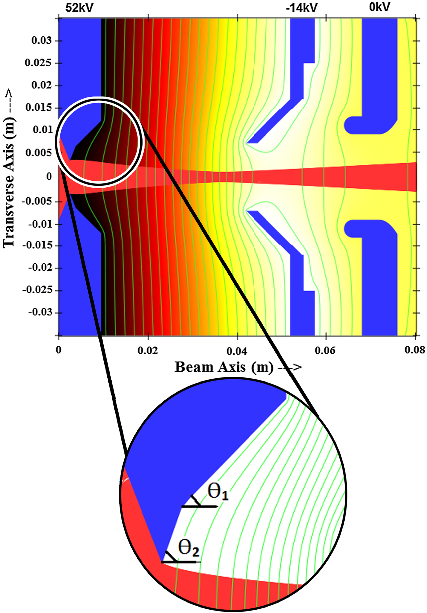
Fig. 3. Pierce geometry and proton beam trajectory simulation in the IBSimu code at 66 kV extraction voltage (the number of iterations is 15, mesh size is 0.05 mm, and gap distance is 37 mm).
It is important to determine the optimized value of Ө1 and Ө2 as if the minimum amount of emittance and the maximum possible current for the ion beam in these optimized values can be achieved. Although the Ө1 = 67.5° is suggested for pierce electrodes (Zhang, Reference Zhang1999), the Ө1 angle is considered in the range of 67–70 in this research because of existence of two angles in this geometry. For achieving optimized Ө1 and Ө2, Ө1 is fixed in 67° at first and Ө2 is varied from 37 to 53°. For each value of Ө2 from this range in 66 kV extraction voltage, 37 mm gap distance and fixed Ө1, simulation with IBSimu code is repeated to reach optimized emittance. Figure 4 shows the variation of beam current and emittance versus Ө2 values in special values of Ө1.

Fig. 4. Variations of beam current and emittance versus Ө2 in special values of Ө1.
Results of simulation show that beam emittance in 10 cm distance from the third electrode has its minimum value for Ө2 = 45°. This simulation procedure is repeated for Ө1 ranged from 68 to 70°. Low emittance value and maximum amount of current occurs for each Ө1 belongs to above range when Ө2 was equal to 45°.
In summary, the most optimized condition is obtained in Ө1 = 68.5° and Ө2 = 45°. The highest current and the lowest value of emittance obtained in these degrees are equal to 7.2 mA and 54 mm.mrad, respectively.
Figure 5 shows variations of beam emittance versus Ө1 in Ө2 = 45°.

Fig. 5. Variations of beam emittance versus Ө1 values in Ө2 = 45°.
Suggestion a new geometry for plasma electrode
Although optimizations carried out on pierce electrode lead to improvement of ion beam characteristics in the available conditions, it is important to reach to a new design of plasma electrode geometry that enables us to extract a high-current low-emittance beam from a helicon plasma source.
For the first time, a parabolic plasma electrode called “Khoshhal electrode” is introduced in this paper. A second degree equation in the form of y = ax 2 + bx + c is used for the design of this electrode. The “c” parameter in the parabolic equation determines the radius of parabolic electrode. By determining a, b, c indices, it may be possible for us to reach to the optimized ion beam. Design of parabolic geometry is shown in Figure 6.

Fig. 6. Parabolic geometry and proton beam trajectory simulation in the IBSimu code at 66 kV extraction voltage (the number of iterations is 15, mesh size is 0.05 mm, and gap distance is 37 mm).
At first, the x term is considered equal to zero; because it is necessary for observation of x 2 index (a) effect in beam characteristics. For this, the range of x 2 index is varied from 30 to 190. It is observed in simulation that with increasing the “a” value up to 150, the value of beam current rapidly increased and after the 150 point especially in the range of 150–190, there is a partial change in the value of this parameter. Thus, the optimum value of “a” is obtained equal to 150. Figure 7 shows the variations of beam current versus “a” values.

Fig. 7. Variations of beam current versus the “a” values.
For proceeding the geometry design procedure, x term is considered in parabolic equation. Results of simulation tests indicate that beam optical properties are widely influenced by “b” variations in parabolic equation. Therefore, “b” values are varied in a limited small range from 0.1 to 1.1; because it is important for us to accurately determine the optimized value of “b”. Variations of beam current versus “b” values are shown in Figure 8. It is obvious that with increase in “b” value, beam current increases.

Fig. 8. Variations of beam current versus “b” values.
Beam emittance parameter is used for the calculation of “b” optimized value. IBSimu continues solving the problems for different values of “b”. Figure 9 shows the Twiss parameters and emittance obtained from the parabolic geometry simulation as a function of “b” values. The Twiss parameters and their relation with the beam emittance are described by Equations 2 and 3 in section “Design considerations: theoretical background”.

Fig. 9. Twiss parameters and emittance as a function of “b” at 66 kV extraction voltage (gap distance is 37 mm).
It is obvious from the figure that by increasing the “b” value, beam emittance first decreases to 26.7 mm.mrad in 0.9 point and then it increases. It can be concluded from simulation results that with using of “a” and “b”, the optimized current and emittance of beam can be obtained respectively. The optimized equation for design of parabolic electrode with considering the diagram is obtained y = 150x 2 + 0.9x + 0.003. It was observed in simulation that with change of “a” value, there will be a change in potential lines located in acceleration region and so the electric field in this region changed. This causes to have the maximum number of particles entering the accelerator region in seventh boundary in which the plasma electrode geometry is described in IBSimu code.
Results and discussion
In this section, simulation results are mentioned to observe the effect of each plasma electrode in beam characteristics in different triode systems.
Variations of extraction voltage
In each of triode extraction geometry, the gap distance of acceleration region is considered equal to 37 mm. The imposed extraction voltage in the acceleration region in each of three geometries is variable from 58 to 70 kV. The imposed voltage to plasma electrode varies from 45.5 to 55 kV. Also, the imposed bias voltage is from −12.5 to −15 kV.
For reducing the emission of secondary electrons from a plasma electrode and also for maintenance of adequate field gradient in acceleration region, EE is biased in negative potential to form an appropriate plasma meniscus boundary. Therefore, we change the imposed voltage of extraction and plasma electrodes to investigate the effect of these changes in beam current, aperture and emittance.
Figure 10 shows the variations of beam emittance versus the extraction voltage for three extraction geometries. As shown in the figure, emittance increases with increase in extraction voltage. The possible minimum value of emittance for pierce geometry with 64 kV extraction voltage and parabolic geometry with 66.5 kV extraction voltage is obtained 54 and 23.1 mm.mrad, respectively.

Fig. 10. Variations of beam emittance versus the extraction voltage.
The intensity of electric field in acceleration region increases with imposing the negative extraction voltage to the EE leading to the formation of a convex meniscus in the plasma boundary surface. Hence, the variations of emittance versus the different values of extraction voltages, as shown in the figure, can be attributed to this type of meniscus shape.
Figure 11 shows the relation between the beam diameter and the extraction voltage in 10 cm distance from GE. For optimized pierce geometry in 64 kV voltage and parabolic geometry in 66.5 kV, the minimum value of beam diameter is obtained at 20 and 9 mm, respectively.
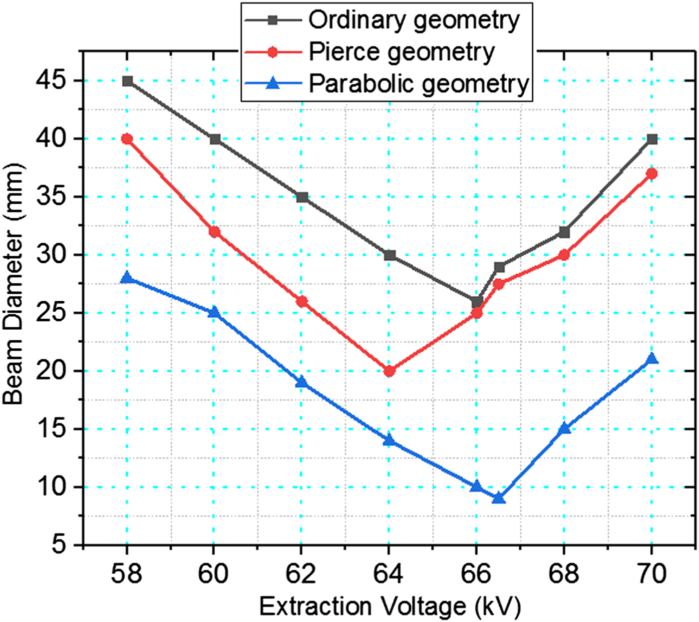
Fig. 11. Variations of beam diameter versus extraction voltage.
Figure 12 shows the current variations versus the extraction voltage. As shown in this figure, for ordinary geometry with 66 kV voltage and pierce geometry with 64 kV voltage, the beam current is obtained 3.7 and 7.2 mA, respectively. The optimum current for parabolic geometry in 66.5 kV is obtained 10.1 mA.

Fig. 12. Variations of beam current versus extraction voltage.
Two-dimensional simulation of parabolic geometry by IBSimu code is shown in Figure 13. The extraction voltage is 66.5 kV and gap distance in acceleration and deceleration regions is equal to 37 and 15 mm, respectively.

Fig. 13. Two dimensional simulation of parabolic geometry and beam trajectory with 9 mm beam diameter in 10 cm distance from the ground electrode.
Variations of gap distance
Optimization of the available distance between the PE and EE for achieving uniform equipotential lines in this distance is so important. This optimization helps to have an appropriate meniscus which enables us to generate a collimated ion beam. With considering the fact that sparks often begin in peaks of field in relative negative potential, choosing an appropriate gap distance can prevent from the electric field breakdown. Hence, in this section, the effect of gap distance variations in beam current, emittance, and diameter is investigated.
The EE distance from the plasma electrode is ranged from 35 to 39 mm. These variations in equal conditions are repeated for each of these three geometries to reach the most optimized gap in each of those.
Variations of beam emittance versus different gap distances shown in Figure 14 indicates that the optimum gap distance obtained for ordinary and pierce geometries is equal to 37 mm. This value for parabolic geometry is obtained at 37.5 mm. The obtained emittance for ordinary and pierce geometries with 66 and 64 kV is equal to 70.5 and 54 mm.mrad, respectively. The best operation belongs to the parabolic geometry in which the imposed extraction voltage is equal to 66.5 kV.

Fig. 14. Variations of beam emittance versus different gap distances (in their optimized extraction voltages).
A typical emittance plot for parabolic geometry in optimized voltage and gap distance is depicted in Figure 15, in which the emittance is equal to 21.2 mm.mrad. This value is obtained in 10 cm distance from the third electrode.

Fig. 15. Typical emittance plot at 66.5 kV and 37.5 mm gap. The calculated emittance is 21.2 mm.mrad in 10 cm distance from ground electrode (α = −31.5829, β = 4.77117 m/rad, γ = 209.273 rad/m).
Figure 16 shows the beam diameter variations versus the gap distance. At first, the beam diameter decreases with increasing the gap distance and then it begins to increase in larger gap distances.

Fig. 16. Variations of beam diameter versus gap distance (in their optimized extraction voltages).
This change may be attributed to the effect of acceleration region in plasma meniscus. It seems that optimization of the acceleration region length is so important for achieving an optimum beam diameter. As shown in this figure, the minimum beam diameter for ordinary and pierce geometries in 37 mm gap distance and in their optimum extraction voltages is equal to 25 and 20 mm, respectively.
This value for parabolic geometry in 37.5 mm gap distance is obtained at 8 mm.
With regard to simulation results, it can be said that the parabolic geometry plays an important role in the formation of convergent and collimated beams. This can be associated to the unique design of this type of electrode leading to the formation of an appropriate meniscus in the helicon plasma boundary.
Variations of beam current versus the different gap distances are shown in Figure 17. It is observed that with increasing the distance between extraction and plasma electrodes, the current increases at first and then it decreases in larger gap distances. For determining the optimized gap distance, an appropriate beam current is required in which the emittance has its minimum value. The optimum current values obtained for ordinary and pierce geometries in 37 mm gap distance are equal to 3.7 and 7.2 mA, respectively. This value for parabolic geometry in 37.5 mm gap distance is obtained at 10.4 mA.

Fig. 17. Variations of beam current versus different gap distances (in their optimized extraction voltages).
Relatively high beam current in parabolic extraction system is due to low current absorption (almost 1 mA) in its plasma electrode. Current dissipation in pierce and ordinary geometries is equal to 5 and 8 mA, respectively.
The most important advantage of parabolic geometry in comparison with other extraction systems is that it can generate low divergence beam with minimum emittance value, fairly high current and relatively high energy (about 66 keV). Therefore, parabolic plasma electrode can be used specially for ion implantation in short times (Ligeon and Guivarcʼh, Reference Ligeon and Guivarcʼh2006; Zhou et al., Reference Zhou, Yu, Han, Cheng, Chen and Zhu2008).
Variations of ion temperature and PE aperture
Variations of beam emittance versus ion temperature in different PE apertures for parabolic geometry are shown in Figure 18. This graph shows that with increasing the diameter of PE aperture, beam current increases. Also, it is obvious from this graph that beam emittance increases with increasing the ion temperature. Beam current for parabolic electrode with 4, 5, and 6 mm aperture diameter in which ion temperature is varied from 0.5 to 4.5 eV obtained 3.1, 6.3, and 10.4 mA, respectively. Variation range of beam emittance for parabolic electrode with 4, 5, and 6 mm aperture diameter is obtained at 13–34, 17–37.3, and 21.2–39.4 mm.mrad, respectively. The obtained results from simulation are in accordance with Equation 1 presented in second section; so, this indicates that ion temperature has major influence on extracted beam optics.
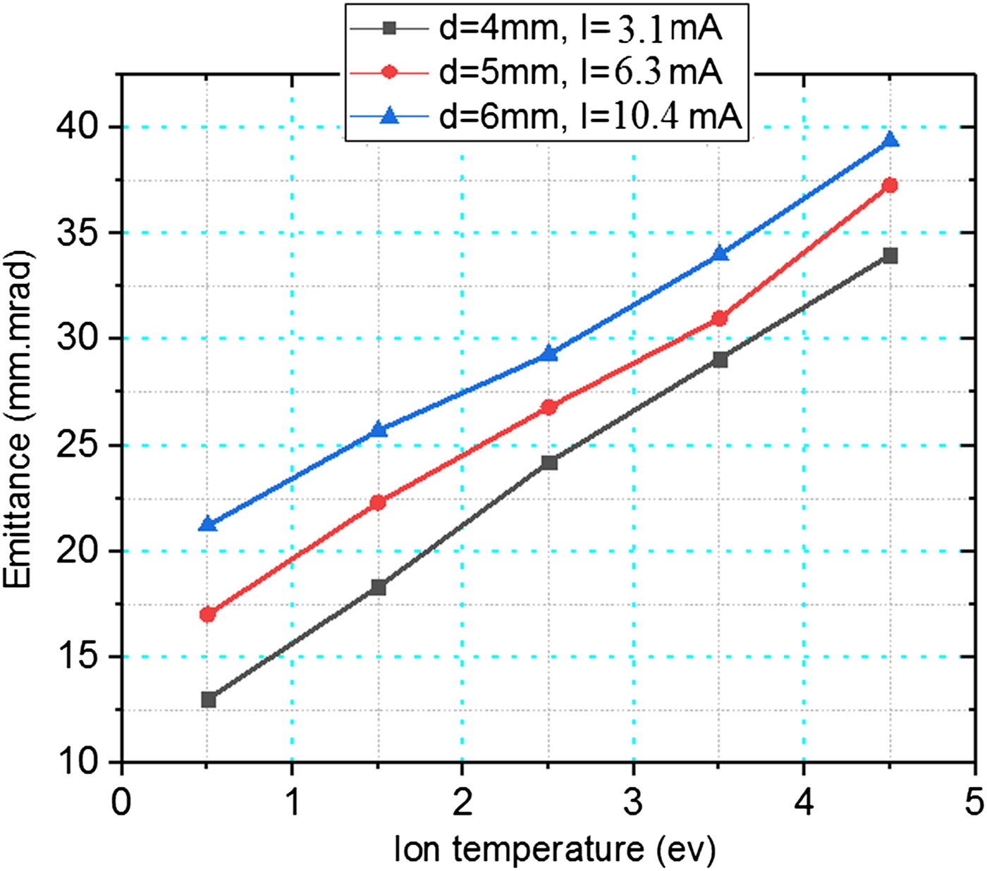
Fig. 18. Variations of beam emittance versus ion temperature, at different PE apertures for parabolic geometry (extraction voltage and gap distance are 66.5 kV and 37.5 mm, respectively).
Conclusions
This work is concerned with determining an efficient extraction system for AHIS used in ion implantation. For mentioned purpose, the effect of plasma electrodes in beam optical properties in three triode extraction systems was investigated. This research is carried out with the aid of IBSimu ion optical code. The dependence of beam characteristics on different parameters of extraction system is investigated and the numerical results lead to qualitative conclusions.
It can be concluded from this research that:
(1) The ratio of EE voltage to PE voltage is obtained as R = 27% with the aid of ordinary geometry.
(2) Minimum value of emittance, maximum current value, and the lowest beam diameter are obtained in 10 mm gap distance. Also, the optimized extraction voltage for ordinary, pierce, and parabolic extraction systems is 66, 64, and 66.5 kV, respectively.
(3) Both of minimum value of emittance (54 mm.mrad) and highest current value (7.2 mA) are obtained in Ө1 = 68.5° and Ө2 = 45° in optimization of pierce electrode.
(4) The parabolic equation indices are optimized (a = 150 and b = 0.9) by beam current, emittance, and Twiss parameters. The Khoshhal electrode has the minimum current absorption and leads to generation of high-current (10.4 mA) and fairly high-energy (66 keV) ion beam. The lower beam emittance (21.2 mm.mrad) and the higher current value of this geometry in comparison with the others indicates its better performance in ion implantation in the short time periods.
(5) The beam emittance increases with increasing the ion temperature in parabolic geometry. Similarly, beam current and emittance increase with increasing the PE aperture diameter.


