


Introduction
High-voltage rectangular pulse generators are widely used in scientific research and industry fields such as high-power microwaves (Korovin et al., Reference Korovin, Rostov, Polevin, Pegel, Schamiloglu, Fuks and Barker2004; Zhang et al., Reference Zhang, Ge, Zhang, Zhang, Fan, Li, Jin, Gao, Ling and Qi2016), X rays (Maenchen et al., Reference Maenchen, Cooperstein, O'Malley and Smith2004), and lasers (Mead et al., Reference Mead, Moncho-Banuls, Pottier and Brasile2009). The pulse-forming network (PFN)-Marx generator is not only the simplest and most widely used high-voltage pulse generator (Glasoe and Lebacqz, Reference Glasoe and Lebacqz1948; Cook, Reference Cook1975) but also the best choice for compact and miniaturized pulsed-power sources with the repetition-rate operation and quasi-square waveform output. Since their compactness and miniaturization properties play an important role in the practical applications (Gaudet et al., Reference Gaudet, Barker, Buchenauer, Christodoulou, Dickens, Gundersen, Joshi, Krompholz, Kolb, Kuthi, Laroussi, Neuber, Nunnally, Schamiloglu, Schoenbach, Tyo and Vidmar2004), extensive research has been undertaken on the miniaturization and application of PFN-Marx pulse generators in the past 10 years (Adler et al., Reference Adler, Gilbrech and Price2009; Li et al., Reference Li, Ryoo, Kim, Rim, Kim and Deng2009, Reference Li, Li, Sun and Zhang2015; Tewari et al., Reference Tewari, Umbarkar, Agarwal, Saroj, Sharma, Mittal and Mangalvedekar2013; Zhang et al., Reference Zhang, Yang, Lin and Yang2013; Liu et al., Reference Liu, Xie, Yuan, Wang, Ma and Jiang2016; Pan et al., Reference Pan, Yang and Cheng2016; Lassalle et al., Reference Lassalle, Morell, Loyen, Chanconie, Roques, Toury and Vezinet2018; Wu et al., Reference Wu, Cui, Gao, Li and Yang2019).
A PFN is the combination of several LC sections into a line network which allows for control of the output power in terms of duration, magnitude, and shape. In their simplest form (e.g., Rayleigh lines), an array of equal inductors and capacitors is used to approximate a transmission line with discrete elements (Cook, Reference Cook1975). In other forms (e.g., Guillemin's theory), the component values are optimized to synthesize a pulse output with a minimum flat-top ripple (Clementson et al., Reference Clementson, Rahbarnia, Grulke and Klinger2014; Rathod et al., Reference Rathod, Anitha, Sholapurwala and Saxena2014). According to Guillemin's theory, a PFN module with fewer LC sections can be designed, although it would typically generate more pulse ripple and longer rise/fall times, but this form facilitates miniaturization of the PFN structure. A two-section PFN module with a pulse width of about 130 ns and a rise time of about 35 ns was designed and tested to make the Marx module more compact (Liu et al., Reference Liu, Xie, Yuan, Wang, Ma and Jiang2016). Comparison of simulation output waveforms between two- and three-section anti-resonance networks were presented (Pan et al., Reference Pan, Yang and Cheng2016), with the results showing that three-section network has faster rise and fall times and longer flat top.
In the previous work, a two-section pulse-forming module with a pulse width of 182 ns, a rise time of 50 ns, and a flat top of 90 ns was developed to meet the requirement of a compact design and square output waveform for a high-power Marx generator (Li et al., Reference Li, Song, Zhu, Jin, Gan and Gong2018; Song et al., Reference Song, Li, Zhang, Gong, Gan and Jin2019a). In research on high-power microwave generation, pulse waveforms with faster rise and fall times are more favorable for the conversion of microwave energy. In order to further reduce the rise/fall times, increase the pulse flat-top duration, and improve the energy utilization efficiency, a Guillemin type-C three-section PFN is developed in this paper. The effect of capacitance deviations on the output waveform was analyzed in the case of both single module and multiple modules, providing technical support for the practical selection and production of the capacitors. Based on the PFN, a 16-stage PFN-Marx generator was developed and tested with the output waveform agreeing well with the simulation shape. The results obtained in this paper provide an optimized approach for the development of compact pulsed power sources to meet the requirements of high-quality pulse waveforms.
Development of three-section PFN based on Guillemin type-C circuit
Analysis of the Guillemin type-C three-section network
The technique used in Guillemin's theory on the design of the PFN is based on the Fourier series expansion of the desired output pulse. The resulting network shown in Figure 1 is known as the type-C Guillemin network and consists of an assembly of resonant LC sections connected in parallel.

Fig. 1. Guillemin type-C PFN circuit derived by the Fourier series analysis.
When the number of LC sections shown in Figure 1 is sufficiently large, a square-wave pulse can theoretically be obtained, and the rise time is infinitely small. Using a Fourier expansion to obtain the values of the capacitance and inductance of each LC section in the PFN, the expression is as follows (Glasoe and Lebacqz, Reference Glasoe and Lebacqz1948):
 $$Ca_n = \displaystyle{4 \over {{\lpar {2n-1} \rpar }^2 {\rm \pi} ^2}}\displaystyle{{\rm \tau} \over {\rm \rho}} $$
 $$La_n = \displaystyle{1 \over 4}{\rm \rho} {\rm \tau} $$
where τ is the pulse width, ρ is the characteristic impedance of the PFN, and n is the number of LC section. In practical applications, it is inconvenient to obtain a square-wave pulse with very small rise time because the capacitors require a wide range of values which makes their manufacture difficult and expensive. In general, it can be assumed that the pulse waveform has a trapezoidal or parabolic rise and fall, which is advantageous for reducing the number of LC section. If the ratio of the pulse rise time to the pulse width is considered to be k, then for a trapezoidal waveform, the values of the capacitance and inductance of each LC section in the Guillemin type-C PFN are expressed as follows (Glasoe and Lebacqz, Reference Glasoe and Lebacqz1948):
 $$Cb_n = \displaystyle{4 \over {{\lpar {2n-1} \rpar }^2{\rm \pi} ^2}}\displaystyle{{\rm \tau} \over {\rm \rho}} \displaystyle{{{\rm Sin}\lsqb {\lpar {2n-1} \rpar k{\rm \pi}} \rsqb } \over {\lpar {2n-1} \rpar k{\rm \pi}}} $$
 $$Lb_n = \displaystyle{1 \over 4} {\rm \rho} {\rm \tau} \displaystyle{{\lpar {2n-1} \rpar k{\rm \pi}} \over {{\rm Sin}\lsqb {\lpar {2n-1} \rpar k{\rm \pi}} \rsqb }}$$
For a waveform with a flat top and parabolic rise and fall:
 $$Cc_n = \displaystyle{4 \over {{\lpar {2n-1} \rpar }^2{\rm \pi} ^2}}\displaystyle{{\rm \tau} \over {\rm \rho}} \left\{ {\displaystyle{{{\rm Sin}\lsqb {\lpar {2n-1} \rpar k{\rm \pi} /2} \rsqb } \over {\lpar {2n-1} \rpar k{\rm \pi} /2}}} \right\}^2$$
 $$Lc_n = \displaystyle{1 \over 4} {\rm \rho} {\rm \tau} \left\{ {\displaystyle{{\lpar {2n-1} \rpar k{\rm \pi} /2} \over {{\rm Sin}\lsqb {\lpar {2n-1} \rpar k{\rm \pi} /2} \rsqb }}} \right\}^2$$
Based on Eqs (1), (3), and (5), the relationships between the ratios of the first-branch capacitance value to the second-, third-, and fourth-branch capacitance value as a function of k for three different pulse rises are presented in Figure 2a–2c, respectively. It can be seen that in solving the three equations for the branch capacitance values, the convergence speeds of the branch capacitance values are different. In Eq. (1), the branch capacitance values are independent of k. In Eqs (3) and (5), the branch capacitance values converge quickly, but the branch capacitance values converge faster in Eq. (3) than in Eq. (5). The fast convergence of the branch capacitance values facilitates the PFN in achieving the desired pulse output waveform with fewer LC sections. Therefore, a trapezoidal pulse is selected in this paper as the ideal waveform for simulation analysis and design. For trapezoidal pulses, if the designed PFN is a three LC-section structure, it can be seen from Figure 2b that the appropriate value of k is in the range of 0.15 > k > 0.1.

Fig. 2. Ratios of C 1 to C 2, C 3, and C 4 as a function of k for three different pulse rises and falls.
For any practical circuit, it is convenient to combine the stray inductances, such as switch inductances and jointing wire inductances, into a single inductance L 4 as shown in Figure 3. In order to obtain the desired pulse rise time t r, the value of the stray inductance L 4 should be designed according to the following expressions:
 $$L_4 = \displaystyle{{t_r^2} \over {C_1 + C_2 + C_3}}$$
 $$t_r = k\cdot {\rm \tau} $$
Fig. 3. Circuit of three-section PFN.
Design parameters of three-section PFN
To meet the requirements of high-power microwaves, the designed three-section PFN module is expected to have a characteristic impedance of 2.8 Ω, an output pulse width of 160 ns, and a rise time of 21 ns. The value of k in Eq. (8) can be calculated as k = 0.13. Using Eqs (3) and (4), the branch capacitance and inductance of each LC section then follow as C 1 = 22.5 nF, C 2 = 2.0 nF, C 3 = 0.4 nF, L 1 = 115 nH, L 2 = 145 nH, L 3 = 260 nH, and L 4 = 18 nH. Based on this set of parameters, the simulated waveforms both with and without the stray inductance L 4 are presented in Figure 4. It will be seen that when the stray inductance L 4 is neglected, the rise time of the output waveform is 15 ns, and the pulse width is 163 ns, which basically meet the expected values as mentioned above. However, it is can be seen that there is obvious overshoot and ringing in the flat top of the pulse. When the stray inductance L 4 is considered, the rise time of the output waveform is slowed to 21 ns, and the pulse width becomes 174 ns, but the overshoot becomes smaller and the flat top smoother, so that the waveform quality is relatively better.

Fig. 4. Output waveforms both with and without stray inductance.
A pulse with a stable flat-top duration, fast rise and fall times is beneficial to the generation of a high-stability, frequency-locked, phase-locked, and high-power microwave (Jiang et al., Reference Jiang, Zhang, Xie and Li2018). Figure 5 shows simulated results of the output waveform of the three-section PFN developed in this paper and the output waveform of the two-section PFN in the paper of Li et al. (Reference Li, Song, Zhu, Jin, Gan and Gong2018). The results show that the three-section PFN has faster rise and fall times for the same pulse flat-top duration, which is beneficial in improving the energy conversion efficiency of the pulsed power into the microwave (Benford et al., Reference Benford, Swegle and Schamiloglu2007).

Fig. 5. Comparison of the output waveforms of the two-section PFN and the three-section PFN with the same pulse flat top.
Effect of capacitance deviation on the output waveform of a three-section PFN module
The capacitances of similar capacitors produced by any manufacturer are not equivalent but have deviations in their parameters. For high-voltage thin-film dielectric capacitors, the nominal capacitance deviation is within ±5%. Capacitance deviation in the PFN adversely affects the quality of the output waveform. Based on a Monte Carlo analysis model in the Pspice circuit simulation program, the effect of capacitance deviation on the output waveform of the three-section PFN is studied when the capacitance deviations are within a Gaussian random distribution. Using the parameters of three-section PFN designed in the section “Design parameters of three-section PFN”, 30 sets of randomly assigned output waveforms are simulated when the capacitance deviations are within ±3 and ±5%, respectively, as shown in Figure 6. It can be seen that when the capacitance deviations are within ±3%, the rise time and flat top of the pulses are basically the same, although the fall time of the pulses is somewhat different. When the capacitance deviations are within ±5%, the rise time of the pulses are the same, but the flat top and the fall time are obviously different. In the development of a single PFN module, in order to ensure the quality of the output waveform, it is necessary to select capacitors with high precision capacitance values. Fortunately, when multiple sets of PFNs are used in a Marx circuit, high-quality output waveforms can be achieved as long as the sum of the positive and negative deviations of the capacitances of the same LC section tends to zero. There is no longer a strict requirement for the capacitance deviations of the capacitors. The section “Testing results” discussed the effect of capacitance deviation on the output waveform in a multi-stage PFN-Marx generator.

Fig. 6. Simulated results using a Monte Carlo circuit analysis when capacitance deviations are in the range of ±3 and ±5%.
Development and testing of a single three-section PFN module
Based on the design parameters, a three-section PFN was developed, using three thin-film dielectric high-voltage pulse capacitors arranged in the form shown in Figure 7 to achieve a high withstand voltage and a compact design. The compact three-section PFN has a size of only 360 mm × 342 mm × 65 mm and a maximum withstand voltage of 120 kV. The “Y”-shaped copper piece developed has the function of three inductors and also serves as a fixed connection piece for the three capacitors, as shown in Figure 8. The junction of the three branches is connected to one of the electrodes of the switch. A set of simple test circuits was built using the PFN module, as shown in Figure 9. The circuit loop consists of a PFN module, a hemispherical gap switch, and a resistive load consisting of three 10 Ω resistors connected in parallel. It is charged by a high-voltage constant-current charging power supply, with a Tektronix high-voltage probe (P6015A) used to measure the voltage across the load. The structural inductance and the channel inductance of the spark gap switch, the distributed inductance of the resistor, and the inductance of the wired aluminum foil together form the stray inductance L 4 in the circuit of Figure 3, and the stray inductance of L 4 is about 60 nH in this test setup. The capacitances and inductances of the three-section PFN developed are the same as the design values. Experimental and simulated results of the output waveforms are presented in Figure 10. The output waveform can be seen to have a rise time of 30 ns, a flat-top duration of 108 ns, and a pulse width of 160 ns. Experimental results agree well with the simulation results. The rise time can be reduced by lowering the stray inductance.

Fig. 7. Arrangement of capacitors in a single three-section PFN module.

Fig. 8. “Y”-shaped copper sheet used in the three-section PFN.

Fig. 9. Simple circuit for testing the output waveform of a three-section PFN module.

Fig. 10. Experimental and simulated results of a single three-section PFN module.
Application of the three-section PFN to a Marx circuit
Effect of capacitance deviation on the output waveform in a multi-stage PFN-Marx circuit
Sixteen PFN stages were assembled to form a Marx generator with the required parameters such as an impedance of 45 Ω, a pulse width of 160 ns, and a flat-top duration of 100 ns. Each stage of the PFN includes three capacitors, and 16 PFN stages giving a total of 48 capacitors. The specific capacitance values are shown in Table 1. It can be seen that the capacitance of each capacitor has high precision, and all the capacitance deviations are no more than ±3% except for one of the capacitors C 3 having a capacitance deviation of 5%. In order to analyze the influence of the capacitance deviation on the multi-stage PFN-Marx, a 16-stage PFN-Marx circuit was analyzed using the Pspice circuit simulation program based on the capacitors used in the experiment. Four sets of PFN-Marx circuit models with capacitance deviations in the range of ±3, ±4, ±5, and ±10% were simulated and compared with the simulation results of ideal and test parameters. Figure 11 shows the simulation circuit diagram of the 16-stage PFN-Marx generator, and the simulation results are presented in Figure 12. The results show that even if the capacitance deviation in a single PFN is large, as long as the average values of each branch capacitance of the multi-stage PFNs are close to the theoretical values, the output waveform is similar to the theoretical result. That is to say, in the design of the PFN-Marx, the capacitance value of each branch capacitor is not required to be consistent with the theoretical value, and only the average value of the same branch capacitors is required to be close to the theoretical value. As long as the sum of the positive and negative deviations of the capacitances of the same LC section tends to zero, a waveform similar to the ideal state can be obtained. This greatly reduces the need for high capacitance accuracy in manufacture. As can be seen from Figure 12, even if the capacitance deviation is within ±10%, the output waveform agrees well with that theoretically predicted.
Table 1. Capacitance deviations of 16 PFN stages used in the Marx generator

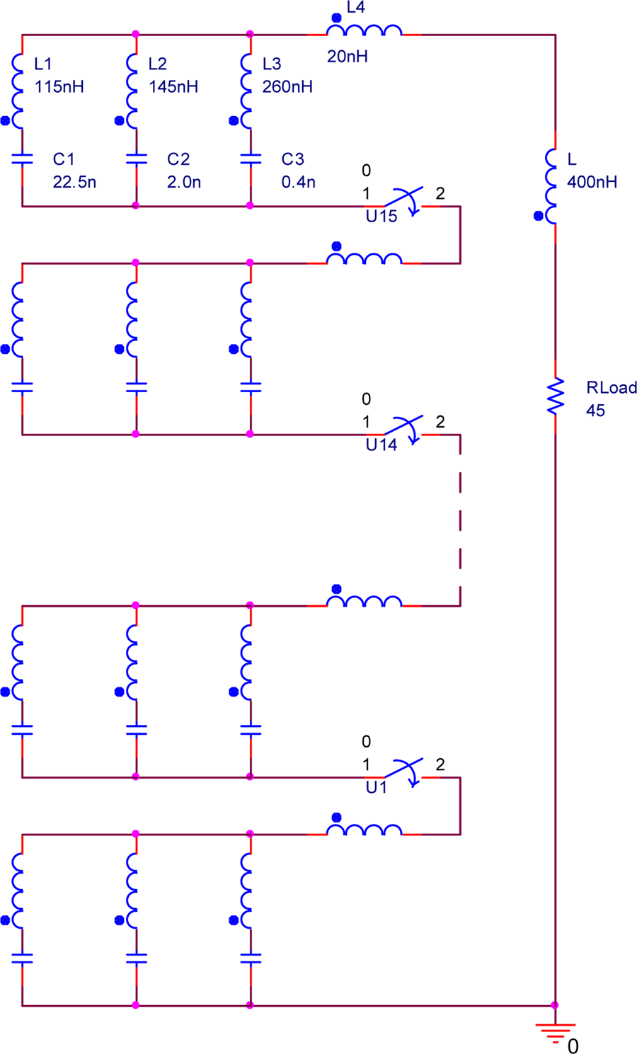
Fig. 11. Simulation circuit diagram of the 16-stage PFN-Marx.

Fig. 12. Simulated output waveforms with different capacitance deviations.
Testing results
The 16-stage PFN-Marx generator developed during this research is shown in Figure 13 and uses a simplified bipolar charging circuit as mentioned previously (Song et al., Reference Song, Li, Zhang, Zhu, Li, Wang, Gong, Gan and Jin2019b). The required design parameters were an output peak power of 12 GW, a maximum peak current of 15 kA, a pulse width of 160 ns, and a flat-top duration of 100 ns. To reduce the loop inductance, the 16 PFNs and 15 switches are arranged in series in a vertical column, and the loop inductance of the 16-stage Marx circuit is approximately 600 nH. Experimental results showed that a peak power of 11.8 GW was obtained on a resistive load of 45 Ω when charging to ±50 kV, with the output waveform having a rise time of 31 ns, a flat-top duration of 104 ns, and a pulse width of 164 ns. The experimental results are consistent with the simulated results, as confirmed in Figure 14.

Fig. 13. 3D structure drawing and photo of the 16-stage PFN-Marx generator.

Fig. 14. Simulated and experimental waveforms of the 16-stage PFN-Marx generator.
However, as can be seen from Figure 14, the fall time of the experimental output pulse is longer than that of the simulated output pulse. In the simulation analysis, three capacitors in a single PFN module are considered to discharge simultaneously to the load, without considering the process of charging the small capacitance by the large capacitance during discharge. However, in the actual discharge process, since the capacitor with a smaller capacitance discharges faster, and the capacitor with a larger capacitance discharges more slowly, in the later stage of the discharge, there is a process by which a capacitor having a larger capacitance charges a capacitor having a smaller capacitance. This process causes the fall time of the output pulse to slow down.
Conclusion
A three-section PFN with a fast rise time of 30 ns, a flat-top duration of 108 ns, and a pulse width of 160 ns was developed and tested to meet the requirement of a compact design, a high withstand voltage, and a high-quality output waveform. Simulation results reveal that the output waveform quality of a single PFN module deteriorates when the capacitance deviation in the PFN exceeds ±3%. Fortunately, when the multi-stage PFNs operate in a Marx circuit, the expected high-quality waveforms can be obtained as long as the sum of the capacitance deviations of the same branch capacitors is approximately zero. This reduces the need for capacitors with high precision capacitance values, which is beneficial for manufacturers in producing capacitors that are inexpensive and meet the practical requirements. To verify the output waveform characteristics of the multi-stage PFNs, 16 PFN stages were assembled to form a Marx generator. When charging to ±50 kV, a peak power of 11.8 GW is obtained on a 45 Ω resistive load. The experimental output waveforms agree well with the simulation results, with a rise time of 31 ns, a flat top of 104 ns, and a pulse width of 164 ns.
Acknowledgment
The author thanks Professor Ivor R. Smith from Loughborough University, UK, for his helpful advice on various technical issues examined in this paper, as well as help provided in English writing.


