


1. INTRODUCTION
The Gesellschaft für Schwerionenforschung mbH (GSI) in Darmstadt, Germany, operates an accelerator facility where almost any element out of the periodic table can be accelerated. Up to three different ion-sources can be used simultaneously. The first accelerator stage is performed by the universal linear accelerator (UNILAC) and provides energies up to 20 AMeV. After passing UNILAC, the ion beam can be used for experiments located at low-energy experimental hall or can be injected into the heavy ion synchrotron SIS-18 with 18 Tm magnetic regidity to increase the energy up to 2 AGeV, depending on charge state and kind of ions. Due to techniques as multi-multiturn-injection, bunch rotating, and compression, the intensity can be increased up to 1010 ions per bunch. Extraction can be performed “fast” (about 120 ns FWHM for 238U73+) or “slow” (up to several seconds). After extraction, the beam can be either stored in the experimental storage ring (ESR) and reinjectet to SIS-18 on demand, or it is delivered to high energy experimental areas, as for example, to the high temperature area (HHT), see Figure 1.

GSI facility—high temperature experimental area (HHT) —present state (left), FAIR accelerators (right).
The main research topics range from biophysics including cancer therapy (Debus et al., 2004), materials research, atomic and nuclear physics, to physics of dense plasmas and high energy densities (HED) in solid states. This latter topic is linked to basic research toward inertial fusion driven by heavy ion beams. Therefore, the accelerator and plasma physics departments at GSI are interested to investigate the properties of intense heavy ion beams as a driver for inertial fusion energy (Hoffmann et al., 2006).
Inertial fusion energy is generally associated with research at major laser facilities (Dewald et al., 2006; Kilkenny et al., 2005; Fleurot et al., 2005). Laser drivers are expected to achieve ignition in the laboratory within a few years from now, however, the route to economically feasible inertial fusion energy still remains open. Heavy ion beam drivers from accelerators offer the option to deliver an intense beam to drive a fusion pellet with high repetition rate and high efficiency. Moreover, due to the high stopping power of matter, especially ionized matter for heavy ions (Hoffmann et al., 1994; Dietrich et al., 1990), the energy is coupled into the volume of the target. Major accelerator laboratories worldwide have been and are currently engaged in projects to investigate the potential of ion beams as drivers for inertial fusion energy (Logan et al., 2006; Neff et al., 2006; Sharkov et al., 2005; Kikuchi et al., 2005; Kawata et al., 2005; Horioka et al., 1998; Meyer-ter-Vehn et al., 1990). The challenge for a heavy ion driver accelerator is to provide short beam pulses (Roy et al., 2005; Tahir et al., 2004) with the highest possible intensity and phase space density on a target at an extremely low rate of beam loss during acceleration and beam manipulation.
To generate HED, intense heavy ion beams are strongly focused within the target volume. The advantage of heavy ions, in comparison to high explosives or lasers, is the uniform heating of large target volumes of several cubic millimeters with almost equal physical conditions. Simulations show that the hydrodynamic response of target material to the ion beam irradiation depends on the beam's temporal and spatial intensity distribution (Varentsov et al., 2005; Temporal et al., 2005). The heating processes and hydrodynamic response of ion beam irradiated targets has first been studied with cryogenic rare gas crystals (Funk et al., 1998) using optical diagnostics. Later a dynamic energy loss diagnostic was developed (Varentsov et al., 2002, 2003) to compare the time resolved beam energy loss with calculated predictions of the hydrodynamic behavior. These experiments showed the importance of knowing the beam intensity distribution at the focal spot. Hence it is essential to have precise information about the beams profile in both space and time, intensity and charge state. This information is needed not only at the beams interaction point with the target, but also within the transfer lines.
In order to compare the results of these experiments to theoretical predictions of the hydrodynamic response, the target temperature, pressure, reflectivity, emissivity, and electrical conductivity have to be measured. Various diagnostics to this purpose are under development. On the way from SIS-18 to the experimental areas (Fig. 1) several beam diagnostics are installed:
Resonant and fast current transformers (RCT and FCT) are measuring the beam's total charge in order to estimate the number of particles and to determine the charge distribution longitudinally with a ∼ns time resolution. Beam position monitors (BPM) are capacitive pickups to detect the beam's center of charge. The only intercepting diagnostics is used in order to determine the transverse beam profile by secondary electron monitor (SEM) grids.
The main disadvantage of these method is that even tungsten made wire grids will melt or evaporate in focused beams with full intensity (HHT: 109 Uranium ions on <1 mm2 in 120 ns), affecting the beam considerably. Due to manufacturing reasons, the wire spacing and therefore the spatial resolution of SEM-grids is limited to ∼0.5 mm which is far away from the required sub-millimeter resolution.
Already for present HED-experiments new techniques for non-intersepting transverse beam diagnostics are needed.
GSI has an approved plan to build the new facility for antiproton and ion research (FAIR) (Henning, 2004) which opens up new perspectives for heavy ion fusion and HED experiments with heavy ion beams (Hoffmann et al., 2005) and advanced plasma-diagnostic by high power lasers (Neumayer et al., 2005; Schaumann et al., 2005). In the future heavy ion facility, intense beams will be transported between several synchrotrons and focused on targets for secondary ion production as well as plasma-physics investigations (Spiller et al., 2006). For the design-case of 5 × 10¹¹ Uranium ions in a single pulse, the focused beam will melt any intercepting material. Especially in future experiments proposed by the high energy density matter generated by heavy ion beams (HEDgeHOB)-collaboration at FAIR, new techniques for non-intersepting high precision transverse beam diagnostics are mandatory.
In the following, two different methods are introduced: The first is a capacitive pickup to determine precisely the beam's position and its transverse dilation ratio at the focal plane by calculating the dipole and quadrupole moment of the charge distribution generated by the ion beam.
The second method is based on beam profile measurement taking advantage of the beam induced fluorescence light in gases as Ar and N2 for example.
2. INSTRUMENTS: CAPACITIVE PICKUP
2.1. Functional principle
The probe is designed as a capacitive pickup with four equal knob capacitor plates. As the beam's longitudinal component (“length”) is long in comparison to the diameter at the focal plane, the beam can be supposed to be a line charge. Therefore the assumption for a cylindrical field distribution—without longitudinal field components—generated by the ion beam is adequate.
By comparing the induced voltage from the four plates, the displacement from the tubes center can be calculated as follows:

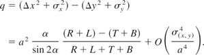
with opening angel α of the plates and tube-radius a. The difference q ≡ σx2 − σy2 is often called “quadrupole moment.” This must not be confused with the quadruple expansion coefficients for a charge distribution!
The measured quadrupole moment is given by Eq. (2) and has to be corrected with the calculated position.
For a centered and circular charge distribution the quadrupole moment is zero.
2.2. Design and implementation
The pickup is designed to be mounted on the four axis target manipulator. Therefore the beams position and quadrupole moment can be obtained in the focal plane of the experiment. The manipulator's advantage is that the pickup's linearity can be tested by moving just the pickup and not by changing the magnet settings.
To obtain impedance matching to 50 Ω-lines, a four channel buffer amplifier is placed on the pickup. In this case, the shape of the signals induced by the ion beam follows the beam intensity with nano-second resolution directly and will not show the time derivative.
As the target chamber at HHT is equipped with a 150 μm thick aluminium entrance foil to keep the vacuum within the beam pipe, secondary electrons are produced when the beam penetrates the foil. To protect the probes amplifier electronics from those electrons, the probe and its electronics is surrounded by a copper housing.
In Figure 2, the pickup can be seen without screening. Two out of the four pickup plates can be seen as well as parts of the amplifiers and the connector for the high flexible coaxial cable.

The capacitive pickup. Two plates and parts of the amplifiers can be seen.
2.3. Calibration
To test the probes linearity, the device was calibrated offline using a Stanford DG535 pulse generator at about 200 different positions. In Figure 3, one can see the normalized voltage difference between the left-right-pair against the position. The two-dimensional-plot is just a projection of the three-dimensional-plot and shows the independency of both axis. Both linear and third-order graphs were fitted. For displacements up to 3 mm, the response is almost linear. Starting from here, the increasing influence of geometrical higher order terms becomes more and more important. The same behavior was observed for the corresponding vertical pair.

Calibration the pair “left-right.”
2.4. Experimental setup
2.4.1. HHT experimental area
The intense and high energetic heavy ion beam is transported from SIS-18 to HHT experimental area via an evacuated transfer tube. During the last meters to the target chamber some bending magnets, two quadrupole-doublets, and one quadrupole-triplet are installed. Using the last quadrupole-triplet, the ion beam can be focused down to sub-millimeter range to generate HED.
The taregt chamber is equipped with a 150 μm aluminium entrance foil to keep the vacuum within the beam line and to have the ability of performing experiments in gas simultaneously. Three vacuum-proof windows are installed for optical diagnostics.
Several targets are stored on a shelf inside the target chamber. They can be moved and aligned with an accurate four axis manipulator.
2.4.2. Data acquisition
Several diagnostics were designed, developed, and tested during last beam times. A fast multi-channel pyrometer to measure surface temperature was tested successfully. The light for the pyrometer is captured by a motorized light collecting system within the chamber and transmitted via three optical fiber lines to the measurement room. In parallel to the pyrometer, a time resolved spectrometer—based on a grid and streak camera—can be used.
Two perpendicular sensitive and high resolution, fast gated CCD-cameras (DiCam Pro, PCO) are installed. They are used for target alignment with an accuracy of about 10 μm. The target expansion is measured with a streak unit and a back-lighting system. Preliminary tests with a laser based interferometer were accomplished. In the future, a “velocity interferometer system for any reflector” (VISAR) will be used for this task.
The beam intensity is determined by resonant current transformers (RCT) attached to the GSI main controlling system. To measure beam profile in time, a fast current transformer is installed short before the target chamber. The probe signals are recorded with a four channel digital storage oscilloscope (Tektronix TDS 3000B) and saved to a personal computer for further processing.
2.5. Experimental data
In vacuum, the secondary electrons produced by the entrance foil are accumulated on the pickup plates, giving a real charge and therefore a wrong signal. Additional electrostatic screening with potentials up to 500 V did not help. Filling the target chamber with p = 50 mbar helium held off the majority of secondary electrons.
A reduced beam intensity of about 2 × 10⁸ ions per bunch was sufficient to get reliable signals.
In Figure 4, one can see the pickup's signals recorded at position (x : y) = (0 : −3.2)mm. The signals from the left and right plates are almost identical, while due to the displacement, the signals from top and bottom plates are different. Additionally, the fast current transformer's signal is plotted to demonstrate its good accordance with the pickup's signal.

Recorded signals at position (x : y) = (0 : −3.2) mm in 50 mbar helium.
2.5.1. Beam position and linearity
The pickup was “scanned” with a comparable raster as during calibration. The results of the calibration was confirmed. Due to beam size and remaining secondary electrons, positions beyond 3 mm displacement were skipped as the signal became unusable.
2.5.2. Quadrupole variation
The field of the last quadrupole magnet of the final focusing system was scanned with different settings. The quadrupole moment as given in Eq. (2) was calculated. As the ion beam does not follow the ideal trajectory at any time, the beam position is influenced by the focus system, too. The beam intensity was again 2 × 10⁸ ions per bunch.
2.5.3. Optical methods
The target chamber was filled with p ≈ 300 mbar argon. Beam intensity was about 2 × 10⁹ ions per bunch. The beam induced fluorescence was captured with the two perpendicular CCD-cameras. Assuming a Gaussian distribution, the quadrupole moment can be calculated using the measured width as the following:


Raw-data of quadrupole scan in argon.
2.5.4. Results
The calculated quadrupole moments from both methods are plotted together in Figure 6. For a effective magnetic field intensity of about B′l = 16.8 T the quadrupole moment became zero as it can be determine from the optical method. The results from the pickup probe are more scattered.

Calculated quadrupole moments determined by gas fluorescence and pickup probe.
3. THE BEAM INDUCED FLUORESCENCE METHOD
As an alternative to the traditional SEM-Grids, the transverse beam profile can be determined by the observation of single fluorescence photons emitted by residual gas molecules. The related device is called beam induced fluorescence (BIF) monitor (Forck et al., 2005), Figure 7. During the last years, the BIF method was applied successfully at the GSI UNILAC for various ions and energies between 4 and 11.4 AMeV in a low pressure regime (1 × 10⁻⁶ mbar N2), (Forck & Bank, 2002). At the plasma physic's experimental area (HHT), profiles of high energy beams (E ≈ 350 AMeV) are measured with fluorescing helium or argon in a high pressure regime of p ≈ (300…500) mbar. Now we investigate its application for higher energies which are available from the heavy ion synchrotron SIS-18 and low N2 pressures. Except for the signal amplitude and profile accuracy, the background contribution is of interest, due to the rising cross section for neutron production.

Scheme of a BIF-Monitor.
The molecules are ionized according to the electronic stopping power and with a certain probability are left in an excited state. For a N2 dominated residual gas composition, a strong fluorescence in the blue wavelength range 390 nm < λ < 470 nm is generated by a transition band to the N2+ electronic ground state (B2Σu+(v′) → X2Σg+(v′′) + γ, for vibrational levels v), having a life-time of about 60 ns (Hughes & Philpot, 1961; Dotchin et al., 1973). “Single-photon counting” is performed with a commercially available image intensifier (Company Proxitronic), equipped with a double mircro channel plate (MCP) for up to 106-fold photo-electron amplification. The light from the P46 phosphor screen with 300 ns decay time is taper-coupled to a digital CCD camera with a FireWire interface (Basler A311f). The device is mounted at a distance of 20 cm from the beam axis, Figure 7. Observing through a wide-angle-lens of 8 mm focal length with remote-controlled iris, leads to a resolution of 377 μm/pixel. A sketch of the optical setup is shown in Figure 8. The setup is installed behind SIS-18 at a distance of 2.1 m in front of a beam dump. It has been tested for different ions (Xe, Ta, U) with energies from 60 to 750 AMeV in fast ∼1.5 μs and slow ∼200 ms extraction-mode. An example of such a measurement is shown in Figure 9: The spots within the area of the vacuum window are created by single optical photons, uniformly superimposed by radiation-events. Their projection along the beam axis yield the horizontal profile. The good agreement of the new method with SEM-grid measurement proves the applicability. However, the BIF method offers a higher spatial resolution, which can be matched easily to other requirements by the choice of an appropriate lens/taper system. In addition, a BIF monitor can be realized in a more compact design compared to an ionization profile monitor (IPM) as another competitive residual gas profile monitor (Forck et al., 2005).

BIF-principle and MCP-schema.

Image from a 1.5 μs long pulse of 2 × 10⁹ Xe48+ at 200 AMeV and the projected horizontal profile compared to a SEM-Grid. The BIF data were recorded at 1 × 10⁻³ mbar and averaged over 20 shots.
3.1. Experimental setup
The details of the experimental realization are described in the following section, see also Figure 7:
Vacuum chamber To minimize photon reflections, the chamber walls were blackened with a vacuum suitable graphite lacquer (graphite grains solved in isopropanol). The view-port is mounted on a Ø 35 mm flange. The gas pressure is regulated via a Pfeiffer (RCV-300) control unit steering a motorized needle-valve (Pfeiffer EVR-116). Combining Pirani and Penning principle, the full-range vacuum gauge (Pfeiffer PKR-251) reaches 5% relative accuracy from 1 bar down to 5 × 10⁻⁹ mbar. Schematic drawing in Figure 7.
Lens system To maximize the solid angle for fluorescence photon detection, the lens was mounted directly on the view-port at 20 cm distance to the center of the beam pipe. Therefore a wide-angle lens with focal length of 8 mm was used. Even at highest aperture 1.4 the depth of sharpness is about 60 mm. Due to the wide pressure range the light intensity had to be attenuated by a remote controlled iris 1.4–16.
Image intensifier The installed image intensifier (Proxitronic BV-2582 TX-V 100 N) has a double (chevron) Ø25 mm MCP setting with a maximum gain of ∼106 (photon-electron-photon amplification). The setup is schematically shown in Figure 8. The captured photons are converted into electrons by a photo-cathode made of UV-enhanced S20, having a quantum efficiency of 25–30% at the interesting wavelength interval and a low dark current of about 500 electrons per second and cm2. The voltage between the photo-cathode and the first MCP can be switched from transfer mode to a blocking mode within 100 ns, enabling an observation only during beam delivery. On a P46 phosphor screen (∼300 ns), each electron-pulse due to a single photon or radiation event is converted into a green light spot (single photon mode).
Coupling and CCD camera To transmit the light from the image intensifier to the CCD, a minifying fiber-optical taper was used, see Figure 8. It is guided in glass-fibers with shrinking diameters leading to a reproduction scale of 25:14. A 12 bit greyscale Basler 311-f camera with 640 × 480 pixel VGA resolution was chosen. The CCD signal is directly digitized at the camera head and transferred using FireWire IEEE1394a protocol.
Data analysis Picture data was processed with a LabView-System. With the program, regions of interest can be selected (view-port/vacuum window) for projection and background determination (outside the view-port region), see Figure 9. Also fit functions and statistical analysis can be applied. During offline analysis corrections like lens-vignetting and profile falsification due to scattered photons have been applied.
3.2. Experimental results
3.2.1. Signal dependence on N2 pressure
For sufficient signal strength on single shot basis, a relatively large pressure bump of typically 10−3 mbar was required for the investigated beam currents. These currents are two to three orders of magnitude lower than expected for FAIR. To legitimate the necessary extrapolation for the FAIR parameters, the vacuum pressure was varied via a regulated gas-valve by nearly four orders of magnitude to larger pressures. To level the higher light intensity at the CCD-sensitivity, the iris opening was reduced and the MCP-gain was lowered; the recorded profiles were then corrected by the resulting factor. Figure 10 confirms the pressure independence of the measured profile width σ, while the total signal amplitude increases linearly with the N2 pressure.

The horizontal profile width α and the total signal amplitude shown as a function of vacuum pressure, determined by the BIF Monitor with the beam parameters of Figure 9.
For the quantitative evaluation of the profile width in Figure 10, two corrections had to be applied: First, the vignetting of the lens system has to be considered, which is particularly important for a short focal length and an open iris. Depending on the profile shape, a correction of the calculated width σ in the order of 2 to 8% is necessary. Second, the fluorescence light reflected at the vacuum chamber leads to a homogeneous distribution with respect to the vacuum window. The projection in beam direction of this round area results in a half-elliptical curve with an integral proportional to the direct fluorescence light. Even though the inner chamber walls have been blackened, about 20% of the acquired light intensity is originated by this reflection. Subtracting the normalized half-ellipse, the shoulders of the raw profile data could be removed independently of the signal amplitude and shape.
For higher pressures p > 1 mbar, a two-step excitation process becomes more important with a probability scaling ∝p2. In the first step, the ionizing collisions between the beam ions and N2 cause free electrons. In the second step, these electrons can excite N2 from the ground state X1Σg+ to triplet-states leading to fluorescence-light in the near UV (337 nm < λ < 358 nm caused by C3Πu → B3Πu + γ). As the mean free path of electrons at 1 mbar is on the order of 1 mm, these electrons could travel a certain distance prior to the molecular excitation. Therefore the measured beam-profile can be enlarged. If the UV-light from the two-step process is suppressed with an optical low-pass filter (GG395) in front of the image intensifier, the measured profile-width is reduced. Even at 2 mbar pressure the contribution is low, as a reduction of only 10% was detected for a beam width σ ∼ 8mm.
3.2.2. Signal dependence on energy
The BIF method should be applied for ion beam energies from 200 AMeV up to 2 AGeV as provided by FAIR. Tests were performed for slowly extracted U73+ ions with energies between 60 and 750 AMeV. The uniformly distributed background was subtracted from the integrated signal and the resulting amplitude is plotted in Figure 11. The energy loss in matter is described by the Bethe-Bloch formula and is characterised by a ∼q2/E dependence. At the BIF-monitor's location, the beam pipe is separated from the transport-lines by a 50 μm stainless steel vacuum window. The energy dependent energy loss Ein − Eout and the electron stripping probability, which depends on the energy too, has to be taken into account. The mean charge states q for the accelerated U73+ were calculated by the code GLOBAL and listed in Table 1 (Scheidenberger et al., 1998).

Total signal amplitude. The signal amplitude for Xe and Ta are normalized by their charge and mass with respect to U.
The energy dependent charge states (U73+) and energy loss behind a 50 μm stainless steel vacuum window, calculated with the GLOBAL-code (Scheidenberger et al., 1998).

Eout and q2 is inserted into the Bethe-Bloch formula and fit to Y = const.(dE/dx)(Eout,q) with relative units in Figure 11. The correspondence to the measured signal amplitude is quite good, proving the proportionality between energy loss and fluorescence yield Y. The data for the other investigated ions Xe and Ta was normalized to the corresponding mass and charge ratios, too, and is described by the same scaling law.
The most critical item for the BIF method is the background contribution. As an example, the BIF-images for the uranium beam with three different energies are shown in Figure 14. The background is uniformly distributed on the image and increases as a function of energy as summarized in Figure 12. It is not caused by optical photons, as proven by the independence on the iris opening and vacuum pressure. Also charged particles can be excluded, due to their limited range in the surrounding material of the image intensifier. In connection with the simulation described below, we conclude, that the main source is related to neutrons created in the 2.1 m distant beam-dump. This was also verified by 6Li and 7Li based thermo-luminescence monitors, where a fraction of ∼80% of the absorbed dose is related to neutrons. About half of them had energies above 20 MeV.

Background level (neutron induced). The background was normalized with respect to the mass only.
The cross section of neutron production rises approximately proportional to the square of the energy and to the number of nucleons (Kurosawa et al., 2000). These neutrons are scattered and slowed down in the surrounding concrete walls. A realistic model of the beam-dump and the cave walls at ∼2 m distance from the beam pipe was used as an input of the Monte-Carlo Transport code PHITS (Iwase et al., 2002). For the case of the 200 AMeV Xe beam, the flux (Fig. 15), energy spectrum and time evolution of the neutrons at the BIF-Monitor location were simulated. The energy spectrum is consistent with the result of the thermo-luminescence monitor. Due to the scattering in the walls, the neutron arrival is delayed with respect to their generation. The measured count rate is shown in Figure 16 and can be approximated by two exponential functions with time constants τ1 = 0.04 ms and τ2 = 2.3 ms. It coincides with the measured count rate by a plastic scintillator beside the beam pass (decay constant τ = 1.7 ms), which was mainly sensitive to neutrons. The background contribution of the BIF-Monitor has the same time behavior, as determined for the fast extracted Xe and Ta beams of 1.3 μs duration and a varying exposure time of the image intensifier between 3 μs and 15 ms. For the short exposure time matched to the beam delivery, the background contribution was reduced by a factor ∼4. This is the reason for the improved signal-to-background ratio of the fast extracted Xe and Ta measurement in Figure 13, compared to the slowly extracted U beam. For slow extraction over several seconds, short gating cannot be applied and thus the background cannot be separated from the fluorescence photons.

Signal-to-background ratio. During fast extraction 1.5 μs Xenon and Tantalum gain a factor 3 to 4 due to delayed neutron background.

Signal-to-background dependence on energy (Uranium) illustrated for different energies.

Neutron-flux per ion for 200 AMeV Xe-ions in the cave, as simulated by PHITS. (Iwase, private communication, Iwase et al., 2002).

The time evolution of neutron arrival at the BIF-Monitor (simulated by PHITS) compared to the counts recorded by a BC400 plastic scintillator. Due to the count rate limitation of the scintillator, the first part up to ∼0.3 ms is not measured properly.
4. CONCLUSION AND OUTLOOK
The capacitive pickup is a compact device to measure the beam's position and its quadrupole moment precisely. The spatial resolution for the beam center can be calculated with an accuracy in the range of ±50 μm while the recorded signals are matching those of the FCTs. Furthermore quadrupole moments were in good accordance to the fluorescence monitor's results. Transverse beam dilation ratio due to different settings of the last focusing quadrupole magnet could be retraced, shown in Figure 6. Secondary electrons may falsify the results and have to be eliminated by a gas-shielding, for example.
The BIF method for non-intercepting profile measurements is an alternative even at energies much above the Coulomb-barrier. Compared to an Ionization Profile Monitor it has a shorter insertion length. In particular, this is important for intense beam in the vicinity of targets. A moderate pressure bump should be acceptable there to achieve a sufficient signal amplitude. For background reduction, a careful shielding of the image intensifier against neutrons is required. To enlarge the distance to the beam pipe, a commercially available ‘Fibre Optics Image Bundle’ might be a solution. A further background reduction can be achieved for fast extracted beam delivery of ∼1 μs where the BIF-Monitor's exposure time ends before all neutrons have arrived. If the image intensifier is installed far from a beam dump or other neutron sources, for example in transport lines, the background is expected to be less pronounced.
Both techniques delivered promising results and will be improved in the future. Furthermore we consider competing methods like inductive pickups, ionization profile monitors, electron scanners or light/x-ray scanners to achieve the common purpose of a non-interception, high resolution transverse beam diagnostic system.


