Published online by Cambridge University Press: 02 June 2005
Irradiation of solid targets by short laser pulses can result in a production of fast ions. In this paper, two production modes are discussed: the controlled amount of matter mode (CAM) and the open amount of matter mode (OAM). The CAM mode is based on laser energy transfer to a controlled amount of matter before the target becomes transparent to the laser light due to the gas-dynamical expansion. For the CAM mode, it is presented a model that allows determining the target parameters, the focusing conditions, and the pulse duration as a function of the laser pulse energy, of the aimed energy per nucleon and of the energy transfer efficiency to the target. The conditions to be this mode experimentally addressed are indicated. The OAM mode relies on the irradiation of a target with large ion content by a short laser pulse; in this case, a small amount of fast ions is emitted from the rear and lateral sides of the target depending on the laser pulse and focusing parameters. For this mode, observed in several experiments, a theoretical discussion is presented. Special attention is devoted to the target normal sheath acceleration (TNSA) and to expansion wave (EW) mechanisms. The EW process is discussed in the framework of a two-temperature isothermal model and some peculiar hydrodynamic processes are discussed.
The production of fast ions by short laser pulses was considered a long time ago (Caruso & Gratton, 1971). The idea was based on the concept that a substantial amount of energy can be transferred to the electrons of a small amount of matter by short laser pulses before quenching of the laser light absorption, caused by target expansion. The energy is ultimately transferred to the ions by quasi-neutral electrostatic coupling during the overall plasma expansion.
In this approach, by a proper target dimensioning, a high energy per nucleon can be in principle obtained by limiting the amount of heated matter (Controlled Amount of Matter mode, (CAM)). As shown in the following, energy per nucleon appropriate for different applications can be achieved by this method.
The CAM mode was more recently reconsidered in connection with the ICF approach based on the injected entropy method, a sort of assisted spark ignition formation technique (Caruso & Strangio, 2001).
To activate the CAM mode high contrast laser pulses are needed. Actually, to get high energy per nucleon, the target to be irradiated can be quite tiny, depending on the laser energy available. This means that any kind of long prepulse has to be kept to a very low level, to avoid target destruction before the arrival of the main pulse. This matter will be addressed below by a proper dimensioning of the target and laser pulse by using a simple model.
The OAM mode (Hatchett et al., 2000; Clark et al., 2000; Roth et al., 2002; Hegelich et al., 2002; Allen et al., 2003; Matsukado et al., 2003) was activated in experiments performed with sub-picosecond PW pulses (several hundred Joules of energy). Multi-MeV protons attributed to target contamination were detected as emitted from the rear and the lateral sides of the target. The acceleration process was attributed to the electric field existing in the negative charge sheath formed, at the rear and lateral sides of the target, by fast electrons generated in the laser-matter interaction zone (Target Normal Sheath Acceleration (TNSA)). The electrons, in transit through the target, are trapped by the charge separation electric field over a distance of the order of λDh = [Th /(4πnh e2)]1/2, where Th is the hot electrons temperature in energy units and nh their local density. In such a sheath electric fields on the order of E ≈ (Th /e)/λDh exist.
The concentration of high specific energy in the proton component of ions was attributed to the highest charge-to-mass number ratios (Z/A) featuring protons. The same mechanism is also active in any ionic acceleration mechanism based on quasi-neutral collisionless plasma EW (Allen & Andrews, 1970; Caruso et al., 1970; Pearlman & Morse, 1978; Denavit, 1979; Gitomer et al., 1986), since in this case, an electrostatic field couples the ions to the electrons (E ≈ (Th /e)/(vs /t), where vs is the ion-sound velocity and t the time). Ionic acceleration by this mechanism has been also considered to explain fast ion production by ultrashort pulses (Wilks et al., 2001).
In this paper both mechanisms (TNSA and EW) for the OAM mode are reviewed. It will be shown that the most consistent scenario for fast ion production is the one in which part of the acceleration process occurs in rarefaction shocks (Bezzerides et al., 1978) embedded in a two-temperature isothermal EW; the rest of the acceleration is provided by the EW itself. The structure of the two-temperature isothermal EW will be discussed with special attention to the energetic of the process (that includes consideration of the heat flow in isothermal structures due to infinite thermal conductivity). It is shown that the position of the discontinuities in the EW is determined by local thermodynamic quantities only. Finally a simple estimate for the amount of fast ions produced is presented.
The interaction of high intensity radiation with solid targets results in the production of high energy electrons beamed in the forward direction and with a spectrum having a logarithmic slope temperature Th equal to the relativistic oscillation energy in the electromagnetic field (Hatchett et al., 2000), that is, Th ≈ 1MeV × (I19 λμm2)1/2, where I19 is the light flux density (in units of 1019 W/cm2) and λμm is the light wavelength (in μm). Of these electrons a (usually) small number escapes the target, the rest being trapped in it by the electric field due to the positive target charge. The fraction of escaping electrons is easily evaluated for fast electrons distributed according to a Boltzmann distribution as (Ne /Th)exp(−K/Th). Ne is the total number of electrons produced by the laser pulse and K is the kinetic energy. Electrons escaping from the target will be the ones with K > Km = α(eQ/a) where Q is the total (positive) charge on the target, e the unit atomic charge, a the typical radius of the charged region, and α a form factor depending on the charge distribution and on the initial position of the escaping electron. For instance, if Q is distributed uniformly in a thin disk of radius a, α = 2 for an electron positioned at the center of the charge surface and α = 4/π = 1.273 for an electron at the disk boundary. The fraction of escaping electrons is f = exp(−Km /Th), whereas Q = fNe e. From these considerations it follows that

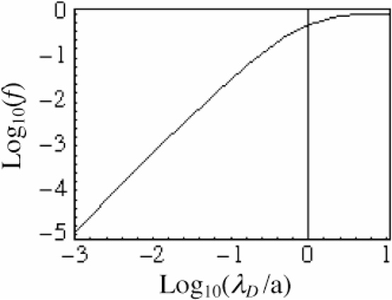
The number ε can be expressed as ε = λD /a where λD = [a3Th /(αe2Ne)]1/2 is the Debye length. Eq. (1) is represented in Fig. 1. The loss of electrons (target charging) will be neglected throughout this paper because, in situations of interest here, ε = 0.003 ÷ 0.03 so that the energy associated to the escaping electrons are much smaller than that of the trapped ones.
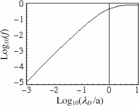
Fraction of fast electrons escaping a target as function of the ratio between the Debye length λD to the charged region size (a).
In the CAM mode the laser light energy is first transferred with efficiency ηt to the target creating a single high temperature (Th) electronic population. Energy is ultimately transferred to the ions by electrostatic coupling in a quasi-neutral, isothermal expansion.
It is assumed that the laser light energy can be transferred to the target before the density ρ becomes less than some critical value, ρt, when the target becomes transparent.
Some degree of beam collimation may be necessary for certain applications. This can be obtained by exploding thin flat targets since the pressure gradient is for these cases essentially normal to the target surface. For this reason in the following treatment we will highlight the case when short laser pulses are used to irradiate thin disks. To provide a dimensioning for this case, we assign the available laser energy (Elaser) and the required energy per nucleon (Enucl). The ionic velocity to be achieved will be

where Mo = 1.660 × 10⁻²⁴ g is the nucleon mass. The initial target aspect ratio (q = Ro /Δo, radius/thickness) is chosen such that transparency to the laser light begins for a plasma thickness of the order of the target diameter, that is when three-dimensional (3D) expansion is also effective. From this it follows that q = Ro /Δo = ρo /ρt, where ρo is the initial target density. The appropriate pulse duration is tpulse ≈ Ro /Vi. From this model simple, useful formula for target and pulse preliminary dimensioning can be easily deduced (Caruso & Strangio, 2001) under the assumption that ρt = ρc is the critical density.
For the target it is found that


where σ is the target mass density per unit surface and λ the light wavelength.
The corresponding formulae for the laser pulse are


where tpulse is the pulse duration and I is the light power density at the target surface. For pulse energies in the kJ range and ionic energies in the MeV range the numerical coefficients in Eqs. (2) and (3) frame properly the target dimensioning, due to the weak dependences from these quantities. A fast dependence on Enucl can be noted for tpulse and I, this last being independent from Elaser. Numerical examples are reported in Table 1. To properly activate the CAM mode it is necessary to use a pulse with an adequate contrast. More precisely the ablation due to any pedestal forerunning the main pulse has to be much smaller than the σ given by Eq. (3). This matter has been recently investigated by Strangio et al. (2004).
Numerical examples

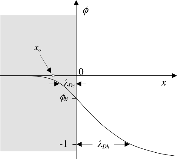
The TNSA mechanism assumes that a negative sheath of thickness λDh = (Th /4πnh e2)1/2 is formed at the rear and lateral target sharp surfaces, due to the fast electrons trapped in the target by self-consistent electric field. In the previous formula nh is the hot electrons density. In what follows the structure of this sheath is described and the motion of a test particle in the structure is studied. It is assumed that the ions with charge Z are at rest with a uniform density nio and occupy the space for x ≤ 0 (one-dimensional (1D) calculations, see Fig. 2). Two groups of electrons are considered: hot electrons (temperature Th, density nho for x → −∞), and cold electrons (temperature Tc, density nco for x → −∞). The electronic density distributions are assumed to be of the hydrostatic type, nh = nho exp(eV/Th) and nc = nco exp(eV/Tc), where V is the electrostatic potential.
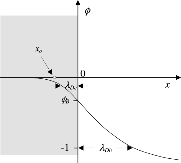
The double layer structure created at a sharp plasma surface by fast electrons. For x [lE ] 0, where an ionic background exists, a positive sheath is formed (ionic excess). For x>0, where ions are absent, hot electrons create a negative sheath.
The following dimensionless quantities will be used: h = nh /nho, c = nc /nco, f = nho /Znio, θ = Th /Tc and the normalized potential φ = eV/Th, so that

The Poisson equation reads

where the coordinate x is measured in units of λD = (Th /4πZnio e2)1/2, the Debye length with temperature Th and density Znio.
Neutrality is assumed for x → −∞, so that for h = c = 1 the second derivative in the first of the Eq. (7) results identically zero. The electric field must be continuous at x = 0 (no surface charge) and zero at ±∞ (global neutrality for the double layer). Eq. (7) can be easily integrated once and the proper conditions for the electric field imposed.


From the continuity of the electric field at x = 0 it follows that the dimensionless potential must be

The approximation is valid for θ >> 1, a situation usually verified (as that f << 1). The corresponding dimensioned value is VB ≈ −(Tc /e)(fθ + 1). In the following we shall consider cases for fθ ≈ 1. In these cases VB ≈ 2Tc /e.
The scale of variation of φ deep in the region x < 0 (that positively charged) is easily obtained from Eq. (8) by using the approximation for φ small, dφ/dx ≈ [f + (1 − f)θ]1/2φ ≈ θ1/2φ. Since the scale for x is λD the distance of variation for φ is λDc = λD /θ1/2 = (Tc /4πZnio e2)1/2. The treatment for the region x > 0 (negatively charged) can be simplified by neglecting the contribution of the cold electrons that is the second term in the r.h.s. of Eq. (9) for θ >> 1. The solution is


The dimensioned scale of variation is

where λDh = [Th /(4πnho e2)]1/2. For x → ∞ the potential φ → −∞ with a slow logarithmic divergence so that, to evaluate the voltage drop across the sheath, a cutoff must be introduced at a distance where the breakdown occurs for the 1D model. This occurs at a distance a, the smaller between the target size and the laser spot radius. The voltage drop is then

. The hot electrons density decreases much faster as

A qualitative plot of the potential φ is represented in Fig. 2 to illustrate the double layer structure. A test ion of charge Zt and mass Mt inserted at position xo in the positive sheath is accelerated toward the plasma surface at x = 0 (see Fig. 2). The extraction time can be evaluated by assuming a simplified form of the potential for φ << 1, namely φ ≈ φB exp(x/λDc). Whence the extraction time (for fθ ≈ 1)

For large, negative z the approximation

holds, whereas for small, negative z the approximation

can be used. Since g(−0.5) ≈ 1.34, for a test particle located within the positive sheath textr ≈ 1/ωhybr, whereas for xo → −∞ the extraction time is exponentially long.
The transit time of a test ion through the negative sheath can be estimated as

and the ratio between the extraction time and the transit time is textr /ttrans ≈ f1/2 << 1. This result shows that an EW is driven in the plasma in a time shorter than the acceleration one. This implies that the expansion wave ought to be considered in the process right from the beginning.
The EW in a collisionless, quasi-neutral plasma has been considered by several authors (Pearlman & Morse, 1978; Bezzerides et al., 1978; Denavit, 1979; Gitomer et al., 1986) also in contexts different from laser plasma interaction (Allen & Andrews, 1970). Important papers on the ionic acceleration by EW have been published in the context of the studies on the plasma plume expansion toward the focusing optics in experiments on laser light interaction with solid targets. The ion acceleration mechanisms by EW in ultra-short pulse interaction with solid targets have been studied by numerical simulations (Wilks et al., 2001).
The EW in a two-temperature quasi-neutral plasma will now be reconsidered analytically. Attention will be paid to the energetic of the process and to the formation of gas-dynamic discontinuities. With regard to the last topic, it will be shown that the position of the discontinuities in a self-similar EW depends on local thermodynamic quantities, the inner structure of the discontinuity being not relevant in the context.
The notation used in the previous section is also adopted in the EW treatment. Since ion motion is now taken into account, the following additional definitions and equations will be used. The normalized ionic density i = ni /nio will be used in the neutrality condition i ≈ fh + (1 − f)c, in the continuity equation di/dt = −i(∂v/∂x), and in the momentum equation, iM(dv/dt) = −ieZ(∂V/∂x). In these equations, v is the flow (ionic) velocity and d/dt = ∂/∂t + v(∂/∂x). The electronic densities h and c are given by Eqs. (6). Eliminating the potential V, the quasi-neutrality and momentum equations become


In Eq. (17), the pressure p is measured in units of nio Mvso2 and vso is the sound velocity evaluated at a temperature Tc.
For a complete description of the process going on in EW, the system of Eqs. (15) and (16) must be implemented by the energy equation. This is always true, also in single-temperature EWs. Actually, in this case, since the temperature is constant through the EW, the internal energy per unit mass is also constant, so that the flow kinetic energy must be due to a flow of heat. In other words, the isothermal expansion wave is driven by an infinite conductivity thermal flow, the electric field being a vector to transfer energy from electrons to the ions, in a sort of thermo-electric acceleration process. The heat flux must be calculated by the energy balance equation, in a way reminiscent of the well-known case of the hydrodynamics of infinitely conductive fluids, where the Ampère law is used to evaluate the current.
The energy equation is

where the heat flux Fh and the specific energy are measured in units of nio Mvso3 and vso2 respectively. The pure number δ accounts for relativistic effects (Cox & Giuli, 1968). Limiting cases are: non relativistic δ = 1; extreme relativistic δ = 2.
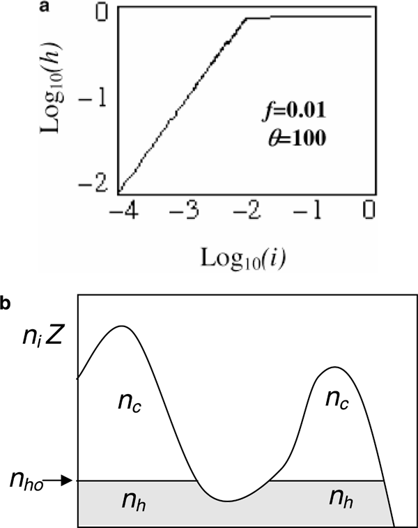
Eq. (15) reveals that for θ >> 1 an abrupt change of regime occurs when i ≈ f. As easily seen, for i < f the approximation i ≈ fh is very good, that is cold electrons are expelled from the regions where i < f (see Eq. (15)). How sharp the transition is can be appreciated from Fig. 3a. In Fig. 3b a pictorial representation of the situation is displayed.
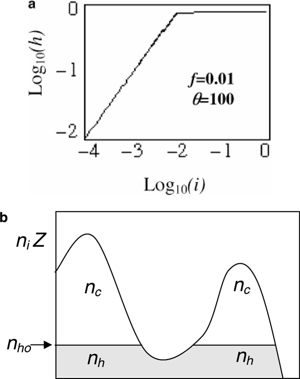
(a) Normalized hot electrons density versus normalized ionic density in a quasi-neutrality regime. For large electronic temperature (θ = Th /Tc >> 1) the dependence shows a sharp change in behavior at i ≈ f = nho /Znio (b) For large electronic temperature (θ = Th /Tc >> 1) hot electrons expel cold electrons from the region where ni Z [lE ] nho.
An additional interesting feature that results from quasi-neutrality and large temperature ratio regards the normalized sound velocity vs2 = dp/di (the normalization unit is vso2 = ZTc /M).

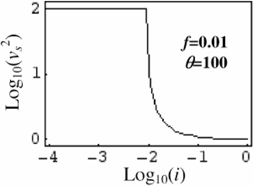
When the density i decreases below f (where i ≈ fh), the value of vs2 pass suddenly from a value on the order of unity to the value φ (see Fig. 4). This means that if the gradient ∇p = vs2(∇i)i=f is evaluated, at this transition, a sudden increase of ∇p occurs and the low-density plasma is strongly accelerated producing a high-energy jet of ions.
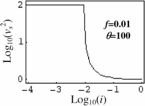
Normalized squared sound velocity (vs2 = dp/di) as function of i. The normalization unit is vso2 = ZTc /M. For large electronic temperature (θ = Th /Tc >> 1) the dependence shows a sharp change in behavior for i ≈ f = nho /Znio, with a transition from the value θ for small i to a value of the order of unity for larger i.
The solution for a self-similarity EW wave can be obtained by standard methods (Landau & Lifshitz, 1959). We assume that the EW starts at x = 0 and propagates towards −∞ into the plasma that occupy the region x < 0 (The region x > 0 is initially empty). The result is


Both vs and v are measured in units of

. Trying a continuous solution everywhere, Eq. (20) is integrated with the boundary condition v = 0 for i = 1 and Eq. (22) with Fh = 0 for i = 0. In the limiting case

. From this it follows that at the left boundary of a conventional single-temperature isothermal EW, the normalized heat flux Fho = θ3/2 must be supplied.
In the general case, non-physical and multi-valued solutions along the variable ξ may result. This occurs where dξ = 0, that is, from Eqs. (20) and (21), where d(ivs) = 0. This happens for

The quantities h+ and h− are real and distinct when 1 − 10θ + θ2 ≥ 0. The equation 1 − 10θ + θ2 = 0 gives the threshold temperature ratio

. The other root is (by symmetry) 1/θthr < 1 and will be not considered. This result is not dependent on f. The usual well known, well behaving solutions for f = 0 and f = 1 (single temperature) correspond to displace the multi-valued quantities region to h → 0 or to h → ∞, respectively.
The behavior of the density i is shown for θ = θthr and for θ > θthr (see Fig. 5). To restore a physical behavior a discontinuity must be introduced (rarefaction shock). At the interface flux of mass, momentum, and energy must be conserved. Another condition is that the discontinuity must be consistent with the self-similar character of the solution. For this reason to the shock must be attributed a constant value of the similarity variable ξs, its velocity. On both sides of the shock, the solutions Eqs. (20), (21), and (22) must be matched. For this reason the flow velocity relative to the shock moving with the velocity ξs is v − ξs = vs that is, a local thermodynamic quantity.
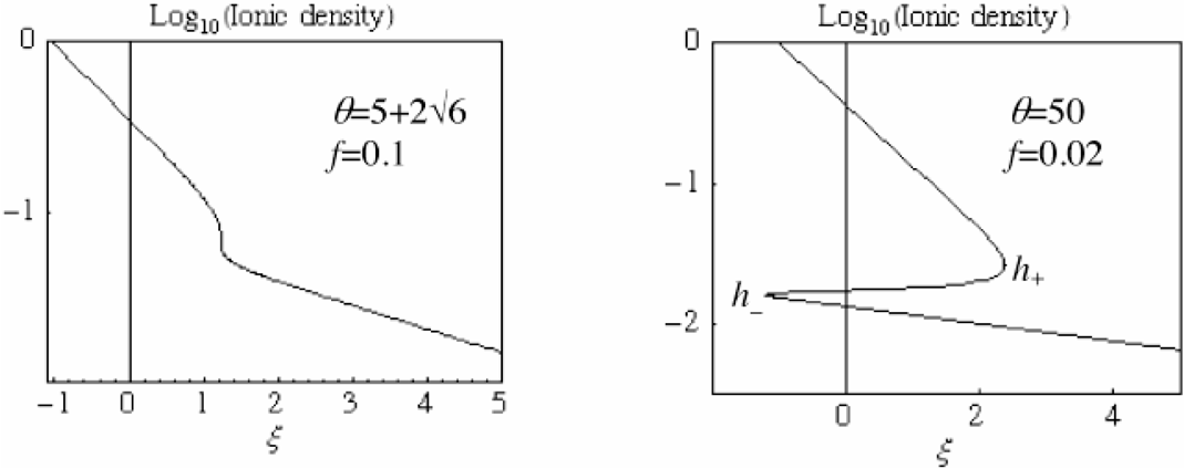
The two-temperature EW displays, for any value of f, a multi-valued behavior for all the quantities when the temperature ratio exceeds .
In the shock treatment the indexes 1 and 2 will be used respectively for the inflow (left side) and for the outflow (right side). The equations for conservation of the mass and momentum fluxes read


Since all the thermodynamic quantities in Eqs. (24) and (25) are functions of h (see Eqs. (15) and (19)), the previous equations allow us to find numerically the corresponding values of h1 and h2. The shock position ξs, and the velocity v2 follow from


In Eq. (26) the flow velocity v1 is obtained by integrating Eq. (20) from h = 1 (where v = 0) to the known value of h1. The quantities vs1 and vs2 are local functions of h1 and h2. A complete description of the flow is obtained by evaluating the velocity for ξ > ξs. Eq. (20) is integrated from h2 where the velocity is v2.
Conservation of energy is used to find the heat fluxes entering and leaving the shock:

The enthalpy is w = ε + p/i and the value of Fh2 is obtained by integrating Eq. (22) starting from h = 0 where Fh = 0, to h = h2. Upstream the flux is evaluated by integrating Eq. (22) starting from h1, where Fh = Fh1. In Fig. 6 a typical case of rarefaction shock treatment is presented.
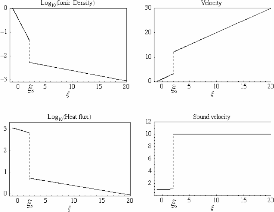
Expansion shock positioning for the case θ = 100, f = 0.01. It is noted the substantial drop in heat flux across the shock and the corresponding increase in flow velocity. Downstream to the shock the flow is practically that of a isothermal EW at the single temperature Th.
Across the discontinuity hot electron density decreases (h2 < h1) and the same occurs for the voltage V:
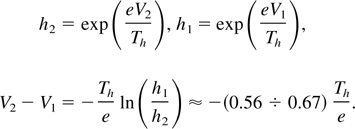
Typically a double layer as described in Fig. 7 will be formed. Associated to this potential drop are the increase in flow velocity (v2 > v1) and the decrease in heat flux (Fh2 < Fh2). The ion acceleration in the double layer appears as due to a potential drop powered the heat flow, in a sort of thermoelectric process.
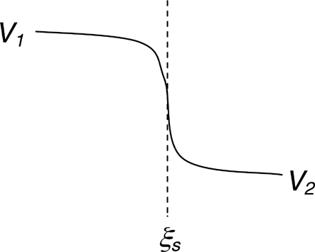
A double layer is formed at the expansion shock in a two temperature plasma. Quasi-neutrality will be violated within the structure.
The flow downstream of point 2 is practically a single temperature (Th) EW. Typical features are the exponential dependences of i and Fh, the linear dependence for the flow velocity v and the constant value of

. This part of the flow represents a low density, quasi-neutral jet formed by energetic ions. The relevant dependences for the main quantities are:


Numerically, for a wide range of the parameters θ and f, it is found:


In Eq. (35) H2 is the dimensioned version of the heat flux Fh2 driving the single-temperature, isothermal EW for ξ > ξs. The quantity Ni represents the number of fast ions per unit surface in this region. Strictly the time t ought to be interpreted as the laser pulse duration, since the light pulse is the source of energy that maintains the hot electrons temperature at the value Th.
The process of fast ion generation by high power short laser pulses interacting with a solid target has been discussed in the context of different regimes.
Fast ions can be generated in the CAM mode by putting a limit on the amount of heated matter by proper target design. Energy is transmitted to the target before light absorption quenching starts due to target expansion. It is found that in this regime the required power density on the target and the laser pulse duration depend critically on the assigned energy per nucleon.
To activate this fast ion generation mode high contrast short laser pulses are required. This is the case because the thin target to be used in this mode could not survive the ablation induced by any long prepulse forerunning the energetic short pulse used to explode the target.
The TNSA scheme has been analyzed and the structure of the double layer at the target surface involved in the process has been studied in the framework of a two electronic temperature model (ions cold at rest). This structure is composed by a positive layer of thickness λDc = (Tc /4πZnio e2)1/2 where Tc is the cold electron temperature and nio the density of ions with charge Z. In the framework of the 1D model used in this paper, the fast electrons form a negative cloud on the surface of the target that creates a logarithmically diverging potential. Clearly a cut-off is needed to evaluate the voltage drop (ΔV) in this negative region. The natural candidate is the minimum (a) between the laser spot and the target size. The result is

where λDh = [Th /(4πnho e2)]1/2. Th and nho are the fast electrons temperature and the density. The scale of variation of the hot electrons density is

.
A test particle placed inside the positive sheath of the double layer is extracted from this sheath in a time much shorter than its transit time through the negative sheath. This means that an expansion wave starts during the ion acceleration process in the double layer, and the picture of a static double layer accelerating ions to energies of the order ZeΔV is not fully consistent.
The acceleration process by a two-temperature isothermal EW has also been considered. All the ion acceleration mechanism appears as a thermoelectric process driven by the heat flow carried by the hot electrons. It is found that essentially the ion acceleration occurs in two steps.
The first step is the transit through a rarefaction discontinuity embedded within the EW, after a modest acceleration in the high-density part of the EW. The introduction of these discontinuities is required because multi-valued solutions in space occur for high temperature ratios (Th /Tc). The positioning of this shock within the EW requires the evaluation of local thermodynamic quantities, the structure of the discontinuity being not involved. The rarefaction discontinuity has the nature of a double layer, where the jump of the accelerating potential is maintained by the absorption of the heat flux flowing through the entire EW structure.
The second step takes place in the EW part located downstream of the rarefaction discontinuity. This part of the EW is practically single-temperature (Th) and represents a low density, high temperature jet emitted by the high-density region.
All the relevant parameters of the ion jet follow from the EW solution without any need for the details of the rarefaction shock structure. Here the number of fast ions contained per unit surface in the jet is:

The time t in Eq. (37) ought to be interpreted as the laser pulse duration, since the light pulse is the source of energy that maintains the hot electron temperature at the value Th.
Fraction of fast electrons escaping a target as function of the ratio between the Debye length λD to the charged region size (a).

Numerical examples
The double layer structure created at a sharp plasma surface by fast electrons. For x [lE ] 0, where an ionic background exists, a positive sheath is formed (ionic excess). For x>0, where ions are absent, hot electrons create a negative sheath.
(a) Normalized hot electrons density versus normalized ionic density in a quasi-neutrality regime. For large electronic temperature (θ = Th /Tc >> 1) the dependence shows a sharp change in behavior at i ≈ f = nho /Znio (b) For large electronic temperature (θ = Th /Tc >> 1) hot electrons expel cold electrons from the region where ni Z [lE ] nho.
Normalized squared sound velocity (vs2 = dp/di) as function of i. The normalization unit is vso2 = ZTc /M. For large electronic temperature (θ = Th /Tc >> 1) the dependence shows a sharp change in behavior for i ≈ f = nho /Znio, with a transition from the value θ for small i to a value of the order of unity for larger i.
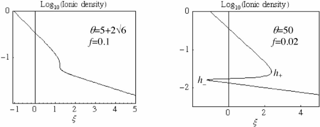
The two-temperature EW displays, for any value of f, a multi-valued behavior for all the quantities when the temperature ratio exceeds .
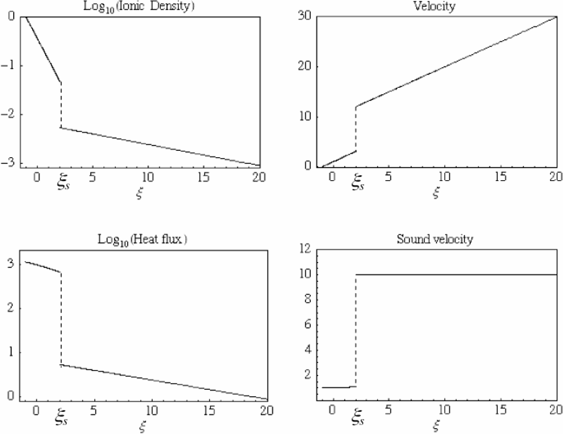
Expansion shock positioning for the case θ = 100, f = 0.01. It is noted the substantial drop in heat flux across the shock and the corresponding increase in flow velocity. Downstream to the shock the flow is practically that of a isothermal EW at the single temperature Th.
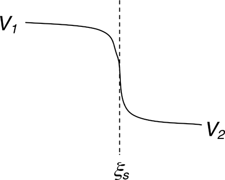
A double layer is formed at the expansion shock in a two temperature plasma. Quasi-neutrality will be violated within the structure.