


INTRODUCTION
Since the hohlraum target plays a key role in the study of indirect drive inertial fusion study, the experimental and theoretical target design, and simulation continuously attract extensive interests and efforts worldwide (Aleksandrova et al., Reference Aleksandrova, Belolipeskiy, Koresheva and Tolokonnikov2008; Atzeni & Meyer-Ter-vehn, Reference Atzeni and Meyer-Ter-Vehn2004; Borisenko et al., Reference Borisenko, Bugrov, Burdonskiy, Fasakhov, Gavrilov, Goltsov, Gromov, Khalenkov, Kovalskii, Merkuliev, Petryakov, Putilin, Yankovskii and Zhuzhukalo2008; Bret & Deutsch, Reference Bret and Deutsch2006; Chatain et al., Reference Chatain, Perin, Bonnay, Bouleau, Chichoux, Communal, Manzagol, Viargues, Brisset, Lamaison and Paquignon2008; Deutsch et al., Reference Deutsch, Bret, Firpo, Gremillet, Lefebvre and Lifschitz2008; Eliezer et al., Reference Eliezer, Murakami and Val2007; Foldes & Szatmari, Reference Foldes and Szatmari2008; Hoffmann, Reference Hoffmann2008; Holmlid et al., Reference Holmlid, Hora, Miley and Yang2009; Hora, Reference Hora2007; Imasaki & Li, Reference Imasaki and Li2007; Koresheva et al., Reference Koresheva, Aleksandrova, Koshelev, Nikitenko, Timasheva, Tolokonnikov, Belolipetskiy, Kapralov, Sergeev, Blazevic, Weyrich, Varentsov, Tahir, Udrea and Hoffmann2009; Li et al., Reference Li, Lan, Meng, He, Lai and Feng2010; Ramis et al., Reference Ramis, Ramirez and &Schurtz2008; Rodriguez et al., Reference Rodriguez, Florido, Gll, Rubiano, Martel and Minguez2008; Strangio et al., Reference Strangio, Caruso and Aglione2009; Winterberg, Reference Winterberg2008; Yang et al., Reference Yang, Nagai, Nakai and Norimatsu2008). The optimal size of a hohlraum is a trade-off between the requirements for energy and power, and the need for symmetry and acceptable plasma filling. Hence, a series of theory for target study have been developed, such as the hohlraum coupling efficiency theory, capsule radiation uniformity theory (Lindl, Reference Lindl, Amendt, Berger, Glendinning, Glenzer, Haan, Kauffman, Landen and Suter2004), and plasma-filling model (Schneider et al., Reference Schneider, Hinkel, Landen, Froula, Heeter, Langdon, May, Mcdonald, Ross, Singh, Suter, Widmann and Young2006). In order to design a suitable hohlraum driven by a given laser source, we often use a two-dimensional (2D) hydrodynamic code to select the optimum hohlraum size by simulation. However, what is the initial size of the hohlraum that we should put into 2D simulation for further optimization? As known, the optimization searching process may be extremely laborious and computationally expensive if without a suitable initial value. In this paper, we will present a method for giving a suitable initial hohlraum size by using an extrapolated plasma-filling model, which was developed under the condition of a constant input laser power (Schneider et al., Reference Schneider, Hinkel, Landen, Froula, Heeter, Langdon, May, Mcdonald, Ross, Singh, Suter, Widmann and Young2006). In the following text, we will first extend the plasma-filling model to the condition of shaped laser pulse. Second, with this extended model, we will give an initial size of a half Au hohlraums, which is driven by a three-step laser pulse on SGIII prototype laser facility. This half hohlraum is used to test the optical diagnostics VISAR on SGIII prototype, and a low plasma filling with maximum achievable radiation is required in the hohlraum. Third, we will use our 2D simulation code Laser with Atomic, Radiation and Electron hydroDynamic code for Hohlraum physics study (LARED-H) (Duan et al., Reference Duan, Chang, Zhang, Wang, Wang and Zhu2002; Pei, Reference Pei2007) to search the optimal size of the half hohlraum by simulation. The initial half hohlraum size obtained from above extended model will be used as an initial input. As it will be shown, the optimum hohlraum size obtained by simulation is close to its initial design. In the fourth part, we further use the extended plasma-filling model to obtain an initial design of the U hohlraum under laser pulse for ignition. Finally, we will present a summary.
PLASMA-FILLING MODEL FOR THE HOHLRAUM DRIVEN BY A SHAPED PULSE
In this section, we first relate the radiation temperature T r to input laser power P and time τ by power balance (Sigel et al., Reference Sigel, Pakula, Sakabe and Tsakiris1988), and then extend the plasma-filling model (Dewald et al., Reference Dewald, Suter, Landen, Holder, Schein, Lee, Campbell, Weber, Pellinen, Schneider, Celeste, Mcdonald, Foster, Niemann, Mackinnon, Glenzer, Young, Haynam, Shaw, Turner, Froula, Kauffman, Thomas, Atherton, Bonanno, Dixit, Eder, Holtmeier, Kalantar, Koniges, Macgowan, Manes, Munro, Murray, Parham, Piston, Van Wonterghem, Wallace, Wegner, Whitman, Hammel and Moses2005; McDonald et al., Reference Mcdonald, Suter, Landen, Foster, Celeste, Holder, Dewald, Schneider, Hinkel, Kauffman, Atherton, Bonanno, Dixit, Eder, Haynam, Kalantar, Koniges, Lee, Macgowan, Manes, Munro, Murray, Shaw, Stevenson, Parham, Van Wonterghem, Wallace, Wegner, Whitman, Young, Hammel and Moses2006; Schneider et al., Reference Schneider, Hinkel, Landen, Froula, Heeter, Langdon, May, Mcdonald, Ross, Singh, Suter, Widmann and Young2006) to the case of a hohlraum driven by a shaped laser pulse.
In a hohlraum driven by a laser pulse, the radiation temperature T r in steady-state conditions is related to input laser power P via the power balance:
where η is the laser-to-X-ray coupling efficiency, A W is the hohlraum wall area, A H is the hohlraum hole area, α is the albedo of wall, and σ is the Stefan-Boltzmann constant. Under a radiation that is proportional to time, the albedo at time τ can be expressed as:
where H, γ, and β are parameters related to radiation temporal profile.
We can approximately relate T r to P and τ from Eqs. (1) and (2) by defining a hohlraum geometrical factor:
in which ![]() is an average albedo of wall over time. Inserting Eq. (3) into Eq. (1), we have:
is an average albedo of wall over time. Inserting Eq. (3) into Eq. (1), we have:
Then inserting Eq. (2) into Eq. (4), we obtain:
where
If an appropriate ![]() is given, then radiation temperature obtained in this way is very close to the accurate solution of Eqs. (1) and (2). When there is a capsule inside the hohlraum or there is a sample on the hohlraum wall, the hohlraum geometrical factor can be redefined by taking the area of capsule or sample into consideration.
is given, then radiation temperature obtained in this way is very close to the accurate solution of Eqs. (1) and (2). When there is a capsule inside the hohlraum or there is a sample on the hohlraum wall, the hohlraum geometrical factor can be redefined by taking the area of capsule or sample into consideration.
In the plasma-filling model (Dewald et al., Reference Dewald, Suter, Landen, Holder, Schein, Lee, Campbell, Weber, Pellinen, Schneider, Celeste, Mcdonald, Foster, Niemann, Mackinnon, Glenzer, Young, Haynam, Shaw, Turner, Froula, Kauffman, Thomas, Atherton, Bonanno, Dixit, Eder, Holtmeier, Kalantar, Koniges, Macgowan, Manes, Munro, Murray, Parham, Piston, Van Wonterghem, Wallace, Wegner, Whitman, Hammel and Moses2005; McDonald et al., 2006; Schneider et al., Reference Schneider, Hinkel, Landen, Froula, Heeter, Langdon, May, Mcdonald, Ross, Singh, Suter, Widmann and Young2006), the laser beam channel is characterized by laser power, electron density n e, electron temperature T e, and ionization state Z h of the hot plasma inside laser channel. The radiation ablated volume surrounding the laser channel is characterized by the radiation temperature T r and electron density Zn i, in which Z is the ionization state and n i is the ion density of the radiation volume. Note that all densities are expressed in unit of the critical density. It is assumed that the laser power per unit length absorbed via inverse bremsstrahlung in the laser hot channel equals to the power per unit length conducted out of the channel by thermal conduction. The filling time for the hot laser channel to reach density n e can be obtained by the pressure balance equation for the laser channel and the surrounding plasma, and the equations relating Z h to T e and Z to T r.
Now we extend this plasma-filling model to a case in which a hohlraum is driven by a shaped laser pulse with high contrasts (>1) between different steps. This condition is widely used in inertial fusion research to produce a time-dependent radiation to assure a nearly isentropic compression of capsule inside the hohlraum and achieve thermonuclear ignition. The maximum radiation temperature in the hohlraum is produced in the last step of laser pulse. We focus on the Au hohlraum here and assume that the differences of T r between steps are large and the mass of wall material ablated in each step of radiation is much larger than that in its former step. Neglecting the influence of former radiation steps on ablation, the mass of wall ablated in each step can be calculated independently. However, in each step the wall albedo increases and contributes to the sum of the ablated mass, which eventually influences the plasma-filling time in the hohlraum.
Assuming that the laser pulse has J steps, we use P j to denote the incident laser power, τj is the time width, T r,j is the radiation temperature, 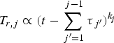 , and αj is the albedo of the jth step (j = 1, … , J). The coupling efficiency from laser to X-ray is assumed to be the same for each step, and then Eqs. (1) and (2) for the jth step become:
The corresponding hohlraum geometrical factor is:
where ![]() j is an average albedo of the jth step. Same as above, we have:
j is an average albedo of the jth step. Same as above, we have:
in which
The mass ablated in the jth step of radiation in Au can be expressed as (Lindl, Reference Lindl1995):
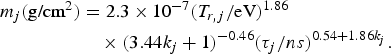
Thus, the total ablated mass is ∑j=1Jm j. We therefore have the material density ρ and the ion density n i in the hohlraum:
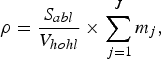
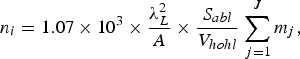
where S abl (cm2) is the effective area of wall being ablated, V hohl(cm3) is the hohlraum volume, and A is the atomic mass of the hohlraum material. Considering hydrodynamic losses and coronal radiative losses from the laser beam entrance hole of the hohlraum, we take S abl = S hohl − S LEH, where S hohl is the inner area of the hohlraum, and S LEH is the area of the laser entrance hole (LEH). For an Au hohlraum driven by a 3ω shaped laser pulse, we have

As we mentioned above, the maximum temperature in the hohlraum will be obtained in the last step of laser pulse, i.e., T r,J = D JP JE JτJF J. Hereafter, we neglect the index J for the last step. As in Schneider et al. (Reference Schneider, Hinkel, Landen, Froula, Heeter, Langdon, May, Mcdonald, Ross, Singh, Suter, Widmann and Young2006), considering the power balance between the laser power per unit length being absorbed via inverse bremsstrahlung in the laser hot channel, and that exiting the channel via thermal conduction, as well as the pressure balance between the laser channel and surrounding plasma, we obtain:
Inserting T r = DP EτF into the above expression and solving for n e, we obtain the average density in the last laser step:
Usually, n e < <1 and ![]() , so Eq. (21) can be rewritten as:
, so Eq. (21) can be rewritten as:
Furthermore, we can obtain the average electron temperature T e in laser hot channel by using the pressure balance 1000 n eT e (keV) = Zn iT r (eV) and the scaling Z = 3.15T r0.45 (Lindl, Reference Lindl1995):
When the plasma filling becomes serious, the laser absorption region shifts far from the hohlraum wall, and more, the hydrodynamic loss and the thin coronal radiative loss from LEH increase rapidly. The density n e = 0.1 is usually used as a threshold that prevents the laser from propagating into the hohlraum due to absorption. For the models concerned in this paper, we use n e = 0.1 as a criterion for giving initial size of a hohlraum in which a low plasma filling with maximum achievable radiation is required. Note that this is different from that used in Dewald et al. (Reference Dewald, Suter, Landen, Holder, Schein, Lee, Campbell, Weber, Pellinen, Schneider, Celeste, Mcdonald, Foster, Niemann, Mackinnon, Glenzer, Young, Haynam, Shaw, Turner, Froula, Kauffman, Thomas, Atherton, Bonanno, Dixit, Eder, Holtmeier, Kalantar, Koniges, Macgowan, Manes, Munro, Murray, Parham, Piston, Van Wonterghem, Wallace, Wegner, Whitman, Hammel and Moses2005), in which λIB = 0.7R LEH is taken as a criterion for a hot hohlraum. Here, R LEH is the LEH radius and λIB is the inverse bremsstrahlung absorption length.
INITIAL DESIGN OF A HALF HOHLRAUM UNDER A SHAPED LASER PULSE ON SGIII PROTOTYPE
In this Section, we use the extended plasma filling model to give an initial design of size of a half hohlraum driven by a 6 kJ three-step laser pulse with 1:4:16 contrasts at 0.35 µm on SGIII prototype laser facility. As it is explained above, this half hohlraum is used to test the optical diagnostics VISAR on SGIII prototype. A low plasma filling with maximum achievable radiation is required in the hohlraum. Eight laser beams from 45° angle of incidence cone simultaneously irradiate the hohlraum from one side. The power profile of the laser beams are shown in Figure 1. The durations of the three steps are 1.5 ns, 1 ns, and 0.6 ns, respectively. The ratio of hohlraum length L to radius R is taken as 1.7, i.e., L/R = 1.7. The radius of LEH is required to be 350 µm, and the laser-to-X-ray coupling efficiency in half hohlraum is around 70% on SGIII prototype.

Fig. 1. Shaped laser pulse on SGIII prototype.
In order to use the extended plasma-filling model to design hohlraum size under a given laser drive, firstly we need to know the temporal profile of the radiation in hohlraum and the time-dependent albedo of the wall in order to obtain coefficients of k j, H j, γj, βj, and ![]() j in Eqs. (10), (11), and (16).
j in Eqs. (10), (11), and (16).
From our simulation, for cases we concern, the radiation profile coefficient k j is mainly decided by laser profile if the plasma filling is not serious. Meanwhile, the albedo profile coefficients, H j, γj, and βj, are mainly decided by k j. The average albedo ![]() j is decided by maximum T r in every step, but only sensitive to T r in the first step when T r is relatively low. Moreover, our study reveals that the radiation ablation behavior of the wall obtained from 2D simulation is very similar to that from one-dimensional simulation. The same result was also obtained in Suter et al. (Reference Suter, Kauffman, Darrow, Hauer, Kornblum, Landen, Orzechowski, Phillion, Porter, Powers, Richard, Rosen, Thiessen and Wallace1996).
j is decided by maximum T r in every step, but only sensitive to T r in the first step when T r is relatively low. Moreover, our study reveals that the radiation ablation behavior of the wall obtained from 2D simulation is very similar to that from one-dimensional simulation. The same result was also obtained in Suter et al. (Reference Suter, Kauffman, Darrow, Hauer, Kornblum, Landen, Orzechowski, Phillion, Porter, Powers, Richard, Rosen, Thiessen and Wallace1996).
Hence, we can first use our 2D code LARED-H to obtain a primary radiation in a half hohlraum with a reasonable supposed size under the given laser pulse, and then use one-dimensional code radiation hydrodynamic code of multi-groups (RDMG) (Feng et al., Reference Feng, Lai and Xu1999; Li et al., Reference Li, Lan, Meng, He, Lai and Feng2010) to obtain the wall albedo under the radiation. Figure 2 shows the temporal T r from LARED-H by taking R as 850 mm and L as 1450 mm, and the corresponding temporal albedo from RDMG.

Fig. 2. (Color online) Temporal T r (red line) in Au hohlraum from LARED-H and albedo (blue line) from RDMG. The hohlraum size is taken as R = 850 µm and L = 1450 µm.
Now, from the radiation and albedo obtained above, we can extract the coefficients by fitting: k j = 0.19, 0.13, 0.12, H j = 8.5, 7, 6.27, γj = 0.66, 0.66, 0.66, βj = 0.54, 0.35, 0.54, for j = 1, 2, and 3, respectively. In addition, we take the average albedo of the three steps as: ![]() 1 = 0.6,
1 = 0.6, ![]() 2 = 0.7,
2 = 0.7, ![]() 3 = 0.75.
3 = 0.75.
Inserting the above coefficients into Eqs. (12) and (20), we obtain the variations of n e and T r as R, as shown in Figure 3. Here, η is taken as 70%. As it is indicated, both n e and T r increases as R decreases. It means that the radiation is stronger and plasma filling is more serious in a smaller hohlraum. Thus, the criterion n e = 0.1 gives the initial design of the half hohlraum as R = 690 µm with T r = 210 eV.

2D SIMULATION RESULTS BY LARED-H
In the last Section, we obtained R = 690 µm as the initial design of the half hohlraum by using the extended plasma filling model. In order to find out an optimum design of the hohlraum size, we now use LARED-H to simulate three models of hohlraum with radii that are close to the initial design: R = 600, 650, and 700 μm. A total of 6 kJ of laser energy entered the half hohlraum from its LEH, and 10% laser energy is deducted after 2 ns due to laser plasma interaction loss from LEH.
In Figure 4, it shows spatial distribution of n e in the hohlraum at 3 ns for the three models. As shown, the region of n e ≤ 0.1 is very small in the hohlraum of R = 600 µm, while relatively large in R = 700 µm hohlraum. In Figure 5, it presents the decay of the laser power in laser beam center along its transferring direction in the hohlraum. As indicated, the laser power decays to 37% of its initial value when it transfers to half of the hohlraum radius for R = 600 µm model, decays to 56% for R = 650 µm, and 77% for R = 700 µm. It means that most part of the laser has been absorbed by plasmas when it reaches half of its way to the hohlraum wall for R = 600 µm model, and hence it is not our optimum model. In Figure 6, it gives T r in the hohlraum for the three models, obtained by post processing along the line about 30° from the hohlraum axis through LEH. As shown, the radiation temperature arrives, its maximum at around 3.2 ns, and it is about 233 eV, 221 eV, and 211 eV for the three models, respectively.

Fig. 4. (Color online) Spatial distribution of N e/N c in half hohlraum at 3 ns from LARED-H for the three models.

Fig. 5. (Color online) Decay of the laser power at 3 ns in laser beam center along its transferring direction in hohlraum for the three models. The abscissa is the radial position at the laser center and is normalized to hohlraum radius. The ordinate is the laser power at the laser center and is normalized to power at the center of LEH.

Fig. 6. (Color online) Postprocessed calculated T r along the line about 30° from the hohlraum axis through LEH at 3 ns for the three models.
In order to get the maximum achievable radiation in a low plasma filling half hohlraum, the model of R = 650 µm is selected as the optimum design for the experiment. The simulation results will be compared with the observations in a follow-up paper with experimental data we are collecting.
INITIAL DESIGN OF 300 eV IGNITION TARGETS OF NIF
In last section, we have used the extended plasma-filling model to obtain an initial design of a half hohlraum size to produce the maximum achievable radiation with low plasma filling under a given shaped laser pulse. In fact, the extended model can also be used to give an initial design of both the hohlraum size and the laser energy to produce a required radiation. Here, we use it to give an initial design of the U hohlraum size and laser energy for producing the typical 300 eV ignition radiation designed for NIF (Hinkel et al., Reference Hinkel, Callahan, Langdon, Langer, Still and Williams2008), although ignition hohlraum is filled with low-pressure gas while the plasma-filling model is made for an empty hohlraum. We take the contrasts between consecutive laser steps from Hinkel et al. (Reference Hinkel, Callahan, Langdon, Langer, Still and Williams2008). The ratio of the hohlraum length to radius is taken as 3.62 and the coupling efficiency η is 75%.
In Figure 7, we present contour lines of T r = 300 eV and ηe=0.1 in the plane of the hohlraum length and the laser energy for U hohlraum under the 300 eV ignition radiation drive. The intersection of T r = 300 eV and ηe=0.1 gives the initial design of 9.3 mm long hohlraum with 0.95 MJ laser energy, which is close to the 300 eV candidate hohlraum design for the 2009 ignition campaign on NIF (Hinkel et al., Reference Hinkel, Callahan, Langdon, Langer, Still and Williams2008).

Fig. 7. (Color online) Contour lines of T r = 300 eV (red line) and n e = 0.1(blue line) in L/E L plane for U hohlraum 300 eV ignition design.
SUMMARY
In conclusion, the extended plasma-filling model can be used to give a reasonable initial design of the hohlraum size under a given laser pulse, or give a initial design of both the hohlraum size and laser energy to produce a required radiation. In particular, we can also have initial design of hohlraum with different geometries by this method, such as rugby-ball shaped hohlraum (Vandenboomgaerde et al., Reference Vandenboomgaerde, Bastian, Casner, Galmiche, Jadaud, Laffite, Liberatore, Malinie and Philippe2007).
ACKNOWLEDGMENT
This work was performed under National Basic Research Program of China (973 program, No. 2007CB814800).


