1. INTRODUCTION
Today much attention is given to modern methods of particle acceleration by intense laser fields (Flippo, Reference Flippo, Hegelich, Albright, Yin, Gautier, Letzring, Schollmeier, Schreiber, Schulze and Fernandez2007; Yin, Reference Yin, Albright, Hegelich and Fernandez2006; Korobkin, 2006). However in this article, we discuss electron beam accelerators with spinal water pulse forming line (PFL), which are widely used in a variety of applications, such as in lasers, high power microwave generators (Korovin et al., Reference Korovin, Kurkan, Loginov, Pegel, Polevin, Volkov and Zherlitsyn2003; Changhua et al., 2002), and X-ray generation (Coogan et al., Reference Coogan, Davanloo and Collins1990; Tarasenko et al., Reference Tarasenko, Shunailov, Shpak and Kostyrya2005), and so on. At present, high repetition rate and long pulse width are important development trend for an accelerator, for high repetition accelerators, or pulse generators. The accelerators for the Sinus series, generated high voltage pulses at repetition rate of 100 Hz, peak power of 10 GW (Mesyats et al., Reference Mesyats, Korovin, Gunin, Gubanov, Stepchenko, Grishin, Landl and Alekseenko2003), and semiconductor opening switch (SOS)-based all solid-state pulse power generator, which generated high voltage pulses at repetition rate of 2–3 kHz (Rukin et al., Reference Rukin, Mesyats, Darznek, Lyubutin, Ponomarev, Slovikovsky, Timoshenkov, Bushlyakov and Tsiranov1999; Lyubutin et al., Reference Lyubutin, Mesyats, Rukin and Slovikovsky1999). The spiral PFL and pulse-forming network (PFN) (Verson et al., Reference Verson and Brion2003; Lancaster et al., Reference Lancaster, Clark and Buttram1988) are the common ways to increase pulse width. As early as 1980, AVCO Research Laboratory of America constructed a single-pulse accelerator based on folded modified spiral PFL (Friedman et al., Reference Friedman, Limpaecher and Sirchis1988) where pulse voltage of megavolt was obtain in a 2 Ω load. At the beginning of this century, the Institute of High Current Electronics combined a Tesla transformer with a spiral PFL of oil dielectric, which allowed a compact and reliable high-current beam accelerator (Korovin et al., Reference Korovin and Gubanov2001). When spark gas-gap switch with forced gas circulation was utilized, at repetition rate of 100 pps, 130 ns, 700 kV pulse were produced in a 150 Ω load. In the investigation mentioned above, transformer oil was employed as dielectrics of the spiral PFL, resulted in an accelerator with large dimension and heavy weight. In this paper, an electron-beam accelerator based on spiral water PFL is described. At present, the diode voltage is more than 500 kV, the electron beam current of diode is about 24 kA, and the pulse duration is about 200 ns. Using the air-core transformer to replace the Marx generator for charging the PFL (Liu et al., Reference Liu, Zhan, Zhang, Liu, Feng, Shu, Zhang and Wang2007) and the water with resistively of more than 10 MΩ cm as dielectric of spiral PFL, as compared with the accelerator of oil spiral PFL, this accelerator is very compact and lightweight. Furthermore, water unusually has a high dielectric constant that is typically 80, and this is about 30 to 40 times higher than most transformer oil. Therefore, the impedance of such an accelerator with this geometrical dimension of oil PFL is lower and more intense current can be generated in the field-emission diode.
2. STRUCTURE OF ACCELERATOR
The construction of the accelerator is schematically shown in Figure 1. It is made up of primary storage capacitors, gas-gap switch with trigger, high voltage pulse transformer, main switch, spiral PFL with water dielectric, and field-emission diode. The primary storage capacitors with capacitance of 16 F can hold voltage of 60 kV. The trigger switch is a field-distortion gas-gap switch. The main switch is a self-breakdown spark-gap switch, and its breakdown voltage can be adjusted by changing gas pressure in the switch. An air-core spiral strip transformer with primary inductance of 5 µH, secondary inductance of 1550 µH, and coupling coefficient of 0.8 is employed to charge water spiral PFL. The spiral PFL with the impedance of 25 Ω, which consists of outer cylinder, spiral middle cylinder, and inner cylinder, is filled with water, which has resistively of >10 MΩ-cm as an insulated dielectric. The spiral middle cylinder was made from stainless steel in a form of single-start spiral. The cathode of field-emission vacuum diode is multi-acicular stainless electrode, 80-mm diameter, and the anode is a stainless steel mesh. The operating process of the accelerator is as follows: while the charging voltage of the primary storage capacitor increased to a certain value, the trigger gas switch was triggered and closed, then the energy-storage capacitor discharges to the primary winding of the transformer. Consequently, the transformer starts to charge the PFL. Once the charging voltage of the PFL reaches the breakdown value of the main switch, the PFL discharged to the field-emission diode, and the high current electron beam will be generated readily in field-emission diode. In present experiments, 200 ns, 500 kV, and 24 kA electron-beam current have been produced in field-emission diode.

Fig. 1. Diagram of the electron accelerator based on spiral water PFL. (1) Primary storage capacitor, (2) Gas-gap switche with trigger, (3) High voltage pulse transformer, (4) Main switch, (5) 5-1(5-2). Resistant divider, (6) Outer cylinder of PFL, (7) Spiral PFL, (8) Inner cylinder, (9) Field-emission diode, (10) Inducing ring for current measurement.
According to the electrical breakdown theory of water, the breakdown voltage of water for negative pulses is about two times larger than that for positive pulses (Fenneman et al., Reference Fenneman and Gripshover1980). In order to guarantee the water spiral PFL works at negative pulse voltage, the gas pressure of the main switch must be adjusted so that the switch will close at the peak of the first negative pulse. Otherwise the water breakdown will happen as a positive pulse exerting on the PFL.
3. THEORETICAL CALCULATION
Because the breakdown process of field-emission diode and gas-gap switch are too complex to calculate the parameters of the accelerator accurately, we suppose that the switches are ideal one, that is, the delay time and energy loss of the switch can be ignored, and the diode is nonreactive and its impedance matches the PFL in the follow calculation.
3.1. Calculation of Electrical Field Strength of Spiral PFL
The designed spiral line was made from stainless steel in a form of single-start spiral. In case of the width of spiral strip greater than the distance between adjacent strips, the breakdown field of the spiral PFL can be reckoned as a conventional one. The width of the designed spiral strip is 400 mm and the average distance between strips is 30 mm. When steep pulse is injected, the turn-to-turn pulse voltage at the rear and front strips of spiral strip is higher than of middle. Therefore, the distances between the rear adjacent strips and between fronts adjacent strips is increased to about 40 mm, which can avoid turn-to-turn of spiral line breakdown at the near and front spiral strip.
The electrical field strengths of the spiral PFL are (Liu et al., Reference Liu, Li and Shen1995)
where r 1, r 2, and r 3 are the radiuses of the inner, middle, and outer cylinders, respectively, U B is the charging voltage of PFL, E mo is the maximum electrical field strength between middle and outer cylinders, and E im is the maximum field between inner and middle cylinders. Both E mo and E im should be less than the breakdown electrical field. It has become customary to express the electrical stress and the maximum durations for which water will hold the stress in the form of a functional relation (Miller et al., Reference Miller1973):
where E max is the breakdown field in MV/cm, K± is dependent on polarity (K = 0.57 for negative electrodes and K+ = 0.33 for positive electrodes), A is the electrode area in cm2, and t is the time of voltage rising from 0.63 U B to U B in µs. As for the designed accelerator, U B = 800 kV, t = 3 µs, r 1 = 5 cm, r 2 = 18 cm, r 3 = 28 cm. With Eqs. 1 to (3), we obtain E im = 0.122 MV/cm, E mo = 0.104 MV/cm, E max = 0.258 MV/cm. Therefore, the PFL can be charged to 0.8 MV without electrical breakdown of water.
3.2. Calculation of Parameters of Spiral PFL
The designed spiral conductor is made from metal spiral strip in a form of single-start helix. PFL can be analyzed with a simple theory. Ignoring the dispersion, electromagnetic wave propagation on spiral strip conductor is along the strip coil and has a component along the axis of the conductor. Propagation parameters, such as speed and current, are 1/cosφ times larger than their axial components, where φ is the pitch angle of spiral strip. The relationship between pulse duration and axial wave speed is inversed, and the same relationship is also between characteristic impedance and axial current. Therefore, pulse duration and characteristic impedance of spiral strip PFL are 1/cosφ times larger than these of conventional coaxial PFL of the same size (Yang et al., Reference Yang, Zhong, Ting and Zhang2005).
Main parameters of a conventional coaxial PFL are as follows (Liu et al., Reference Liu, Li and Shen1995; Lewis et al., Reference Lewis and Wells1965):

Where c is the velocity of light in vacuum; εr is the relative electric permittivity of the dielectric; l is the length of cylinder; T is pulse duration; C 1 and C 2 are capacitance per unit length of the inner and outer line of PFL; and Z 1 and Z 2 are characteristic impedance of the inner and outer line. According to Eq. (4), the pulse duration and impedance of the spiral PFL are

Considering Eqs. (4) and (5), spiral PFL can be regarded as a conventional coaxial PFL as long as the spread of spiral conductor. The spread is presented in Figure 2. In Figure 2a, the conductor is unexpanded in Figure 2b, it is partly expanded; and in Figure 2c, it is expanded completely. The length of the expanded conductor is ![]() . Where l is the length of cylinder; r 2 is radius of the cylinder; N is the number of turns; and n is the number of turns per unit length. If n ≫1/r 2, the length can be written as 2πr 2N or 2πr 2nl.
. Where l is the length of cylinder; r 2 is radius of the cylinder; N is the number of turns; and n is the number of turns per unit length. If n ≫1/r 2, the length can be written as 2πr 2N or 2πr 2nl.

Fig. 2. Spread of the spiral conductor.
Following equations gives the relationship shown in Figure 2:

Substituting Eq. (6) into Eq. (5), we obtain:

As for the designed PFL, l = 135 cm, r = 81, n = 2.5. With Eq. (7), we obtain T = 174 ns, Z 1 = 18 Ω, Z 2 = 6 Ω. Hence to match the PFL, the impedance of field-emission diode is 24 Ω.
3.3. Theoretical Analysis of Diode Voltage
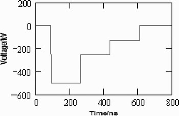
According to the PFL theory (Liu et al., Reference Liu, Li and Shen1995; Lewis et al., Reference Lewis and Wells1965), the diode voltage U D is:
![\eqalignno{\hbox{when}\; & 5 \tau \leq t \leq 7 \tau \quad U_D = - {2R_d \over R_d + Z_1+Z_2} \cr \quad & \times \left[{R_d^2 - \lpar Z_1+Z_2\rpar ^2 \over \lpar R_d + Z_1 + Z_2\rpar ^2} + {4\lpar Z_1 - Z_2\rpar ^2 \over \lpar R_d + Z_1 + Z_2\rpar ^2} \right]U_B}](https://static.cambridge.org/binary/version/id/urn:cambridge.org:id:binary:20151021081604112-0734:S0263034607000705_eqn10.gif?pub-status=live)
where τ is the wave transmit time and ![]() . The charging voltage U B of spiral PFL is 500 kV, and impedance R d of the field-emission diode is 24 Ω, which is matched to the impedance of spiral PFL. With Eqs. (8) to (10), diode voltage waveform is shown in Figure 3. The diode peak voltage is 500 kV and the pulse duration is 180 ns.
. The charging voltage U B of spiral PFL is 500 kV, and impedance R d of the field-emission diode is 24 Ω, which is matched to the impedance of spiral PFL. With Eqs. (8) to (10), diode voltage waveform is shown in Figure 3. The diode peak voltage is 500 kV and the pulse duration is 180 ns.

Fig. 3. The voltage waveform of field-emission diode
4. SIMULATION
4.1. Simulation of Electric Field Distribution and Voltage Waveform of Spiral PFL
For designed spiral PFL, the Karat code is used for the simulation of diode voltage and electric field distribution of spiral PFL. Figure 4 is the geometry of the spiral PFL. The structure of the PFL is coaxial, so a two-dimensionally axial-symmetric model can be used in simulations to reduce the calculation scale. The lines in 5 cm and 28 cm of the r-axis are inner and outer cylinders. The line between outer and inner cylinders is spiral middle cylinder, and voltage of −600 kV is exerted on it. It is defined to be zero voltage at outer and inner cylinder. V#1 to V#4 is the space with conductance or dielectric. For appropriate conductivity, V#1 and V#2 correspond to the switch between middle and inner cylinders, and the load between inner and outer cylinders, respectively. And for appropriate electric permittivity, V#3 is the water dielectric, and V#4 is the polyethylene as an insulating and supporting board between the PFL and diode.

Fig. 4. Cross section of spiral PFL.
The electric field distribution and output voltage waveform are simulated by the Karat code. The results are shown in Figures 5 and 6. According to Figure 5, the field varies greatly at terminals of PFL. In this case, turn-to-turn breakdown is caused easily. To avoid it, at terminals, distances between adjacent strips should be increased. As can be seen from Figure 6, the pulse duration is above 180 ns, which approximately is in agreement with the result of theoretical calculation.

Fig. 5. Electric field distribution.

Fig. 6. Output voltage waveform.
4.2. Circuit Simulation
Pspice circuit analysis was used to model the accelerator based on spiral water PFL. Figure 7 shows schematically the circuit model. The whole circuit is connected with components built in Pspice component storage or modeled by the authors according to the performance of the device. Parameters of all components in the circuit are valued according to the practical circuit or theoretical calculation given in Figure 7.

Fig. 7. Circuit schematic for simulating the accelerator.
As shown in Figure 7, the spiral strip transformer is modeled and indicated by Xform1 in the circuit with primary winding inductance of 5 µH and secondary winding inductance of 1550 µH, for a coupling coefficient of about 0.8. C25 is the primary energy-storage capacitance, and R34 and L12 are the resistance and inductance of primary winding circuit. The main switch in the accelerator is modeled and indicated by Gap_main in the circuit. T_mid_inner and T_mid _outer are connected in parallel to simulate the spiral PFL. The Diode is modeled and indicated by R37 in the circuit.
In simulations, the energy storage capacitor initially charged at 40 kV, and breakdown voltage of main switch is 500 kV. The waveform of the charging voltage of the PFL is shown in Figure 8a. And the waveforms of voltage and current in the resistant load are shown in Figure 8b. According to Figure 8, the diode voltage is more than 550 kV, the electron beam current of diode is about 23 kA, and pulse duration is about 200 ns. Hence, the peak output power of accelerator is more than 10 GW theoretically.

Fig. 8. Simulation result of voltage and current signals.
5. EXPERIMENTAL RESULTS
In experiments, the primary storage capacitor (16 µF) was initially charged at 40 kV, and the charging waveform of PFL is shown in Figure 9. According to Figure 9, the peak charging voltage is about 540 kV in 7.8 µs. The waveforms of the diode voltage measured by resistant divider and current measured by inducing ring are shown in Figure 10 (CH1: voltage waveform; CH2: current waveform). The diode voltage is 500 kV, the electron beam current of diode is about 24 kA, and pulse duration is 200 ns. The experimental and simulated results are in agreement.

Fig. 9. Charging voltage waveform on spiral water PFL.

Fig. 10. The diode voltage (CH1) and diode current (CH2) waveform of accelerator.
6. CONCLUSIONS
Using spiral PFL to modify the coaxial one is an effective method to achieve long pulse. In this paper, the main parameters of the accelerator were calculated. The distributions for electrical field in the PFL were obtained by the simulation through the Karat code. In addition, the process of the accelerator charging a spiral PFL was simulated through the Pspice software to get the waveforms of charging voltage of PFL, the diode voltage and diode current of accelerator. The theoretical and simulated results agree with the experimental results. According to the theoretical analysis, an electron-beam accelerator based on spiral water PFL is constructed. It consists of a primary storage capacitor system, an air core spiral strip transformer, a spiral PFL of water dielectric and a field-emission diode. In present experiment, the diode voltage is 500 kV, the electron beam current of diode is about 24 kA, and pulse duration is 200 ns. In the future, the utilization and repetition of this accelerator will be further investigated.
Acknowledgments
The author wishes to thank B. L Qian and Y. G. Liu for his encouragement and valuable suggestion. The assistance of L. R. Xu, X. Zhou in the assembly and testing of accelerator is also gratefully acknowledged. This work was supported by the Chinese National Natural Science Foundation under Grant No. 10675168.