


1. INTRODUCTION
A bottleneck for global problems in the middle of this century is widely recognized as being due to our consumption of fossil resources. This consumption is accelerated by global increases in population, so rapidly is this increase, it is commonly said that CO2 free energy resource is strongly required as soon as we can (Steffen et al., 2005).
CO2 free and decentralized energy source is expected to be a fundamental energy source in the future. To produce hydrogen efficiently as clean energy and to use it instead of fossil energy will be one of the solutions. Inertial fusion energy (IFE) may contribute to the solution of the problem, but today, it is still an area of intense theoretical and experimental research (Kilkenny et al., 2005; Koresheva et al., 2005; Leon et al., 2005; Miley et al., 2005; Perlado et al., 2005). Using IFE to produce hydrogen was proposed but detail has not been considered seriously because of the high temperature needs to produce hydrogen with liquid lithium in an IFE reactor (Maniscalco et al., 1978; Logan et al., 2006). Besides this, IFE reactor had been considered to require very high gain. In this case, fine target and huge laser is required, which makes it difficult for civilian application. So for a civilian application of IFE, a conversion to electricity of the centralized energy has been considered mainly.
But in this article, using an IFE application, we will show a rather low gain for hydrogen production. We need a more detail design for this, concerning many items like neutron behavior in the blanket, energy conversion to make a higher temperature, tritium breeding section, first wall, stress on the outer shell, efficient laser to drive a pellet, and so on. Research on theses items are under way and are to be addressed in the next step. The IFE reactor for this purpose is discussed in Section 2. We will describe an example of hydrogen production in Section 3. Section 4 is a summary of this article.
2. CONCEPT OF THE APPROACH
2.1. Reactor concept
This IFE reactor has a magnetic field to separate neutron and charged particles to get a higher temperature in a solid blanket in order to produce hydrogen. In this reactor, we also use a direct energy conversion of charged particles (Lasche, 1983). High conversion efficiency with efficient laser makes a breakeven with low gain in a range of 20 MV to 30 MV using the charged particles energy.
Figure 1 shows a schematic picture of this concept. Energies from neutron and alpha particle are mainly produced at the center of this reactor by a Deuterium–Tritium ignition, and following a burning process of the pellet target. Most of the alpha particle energy and a few of the neutron energy are deposited in the plasma during inertial time. Neutron and charged particle are separated by the magnetic field and deposit their energy in a blanket or direct converter, respectively. Direct conversion was investigated (Moir et al., 1974). An efficiency of direct conversion was shown to be 70 to 90%.

Energy flow of this reactor with typical parameters. Neutrons and alpha particles generated by fusion reactions are separated by the magnetic field. Neutrons carry their energy into the graphite blanket and are stopped. Alpha particles are trapped by the magnetic field and escapes through the loss cone when mirror field is applied.
Recent laser technology allows us to take a total efficiency of laser system from 30 to 40% including doubling the frequency. Such efficient laser and direct conversion induce a breakeven with low gain from target of 20 to 30 in this case, even when neutron energy is excluded.
This reactor has similarities to mirror machine for magnetic confinement. Charged particles generated in the target as plasma are trapped in the magnetic field. They come out gradually through the end loss. A characteristic time is to be a few hundred microseconds, although the burning time of high dense laser fusion target is less than a nanosecond. A Lamoure radius of energetic ions in magnetic field is set to less than one tenth of the radius of this reactor, where the plasma is confined. Instabilities in this system may be considerable, but the efficiency for final conversion is not affected so strongly. Very low dense plasma is confined easily in microsecond periods because the density of the plasma is less than 1013–1016/cm3 when the target plasma expand and comes to be uniform in this mirror magnetic field.
In our IFE reactors, stress is caused mainly by the charged particles. In this scheme, the charged particles are trapped by the magnetic field and travels in the direction of the field. The magnet coil causes the reduction of stress on the wall and blanket. Direct stress is reduced in strength and time significantly.
The repetition rate and efficiency of the laser are important to get economical hydrogen as an energy resource in this system. A ceramic laser is to be used. This laser property is a combination of crystal and glass, and this combination has been expected to have the advantages for an IFE driver. High doping rate can be expected, which induce a high output power. High conductivity is also expected to escape the thermal effect. We can make a large diameter laser disk from glass.
The use of ceramic material with lasers is well established. Ceramic laser has shows the expected high potential for fusion driver as a high laser gain, feasibility of large size scalability, and high thermal conductivity (Nakatsuka & Saiki, 2003). In Figure 1, Q is the gain of the target, and in this case, it is assumed to be 30. The output from the thermonuclear reaction is composed of neutron and alpha particles. A large part of the alpha particles with about one-fifth of the generated fusion energy is collided in the target, and deposits their energy after fusion reactions. This makes high temperature plasma and the plasma expands to the volume of the confinement region of 10 m3, although the target volume is about 1 mm3. In this case, the expansion is expected to be 1010 times; besides the time expansion of sub-nanoseconds, the burning time expands to microsecond confinement time with the end loss.
Characteristic time of end loss is hundred microsecond. So the particle through the end loss is low density and can be separated as a charged particle easily, thereafter the particles of plasma is converted into electric power directly.
Neutron is scattered in the target but this amount is small. Most of the energy from the neutron reaches the blanket of solid graphite and is deposited. Around 10% of the neutron energy is deposited in the target.
The combination of mirror machine and gas cooled graphite blanket withstand a temperature of more than 2000 K. Neutron to thermal energy conversion is the most important issue in this design. The detail simulation is on the way. The rough estimation for a hydrogen production temperature of 1600 k is assumed to get an efficient production of hydrogen. The temperature of blanket can be more than 1600 K; hydrogen production efficiency is estimated to be almost 65% by a simple model of Carnot cycle.
Breeding of Tritium in a blanket is expected to be more than 1 in the fusion reactor. A layer of lithium compound ceramic ball is set at the end of a blanket in our case. We have not obtained Tritium breeding, yet. We are going to add the layer of lithium compound ceramic ball behind the first wall. In the usual fusion blanket for gain of 1.2 is expected by generated gamma ray, knock on particles, and so on induced by fusion neutrons.
2.2. Reactor configuration
The reactor is cylindrical to apply a simple mirror field. At the center of the reactor, the target is injected and is tracked by laser technologies. After the target ignition, energetic charged particles generated by the alpha particle are expanded in the mirror field. By the thermalization of confined plasma, particles fall into a loss cone. Charged particles drift into the transport area and come into the energy converter. Fan shaped energy converter is a kind of energy analyzer. Magnetic field applied to converter separate low dense plasma for their energy and charged state and makes a direct conversion of their energy to electricity.
Here we consider the reactor with a solid-state blanket of graphite for neutron energy capture. This graphite blanket has many holes of small diameter and helium gas as a coolant passes through them. This is similar to a high temperature gas fission reactor. A rough illustration of this fusion reactor is shown in Figure 2. This is a laser driven reactor and we can put off the motion immediately when we stop the energy flow. So we can sustain the high temperature with enough safety. For graphite blanket, the temperature of the gas can be more than 1600 K to make hydrogen efficiently.

Illustration of the reactor with mirror magnetic field and graphite solid blanket. The reactor is cylindrical and the target is injected at the center. Charged particles are expanded and fall into a loss cone. They drift into the transport area and come into the energy converter. Fan shaped energy converter is energy analyzer. Magnetic field applied to converter separate low dense plasma for their energy and charged state.
The first wall inside of the blanket is ceramics. The low Z first wall makes low activation and can be replaced at appropriate time, under regular investigation as fission reactor is received. High-pressure helium gas as a coolant is pumped through the coolant channels. The outer shell has layers inside filled with ball of lithium compound ceramic for Tritium breeding. As Tritium diffuses out of this ceramic ball of lithium compound, it is removed from the layer by the helium gas coolant. The advantage of graphite blanket is to exhibit 1ow activation, and in the case of the accident, released radioactivity is greatly reduced. The graphite moderates the neutrons below activation energy levels. The outer shell is stainless steel to withstand the high temperature and stress. This is covered and is supported by the reinforced concrete vessel. This also plays a role in neutron shielding.
2.3. Reactor parameters
Reactor structure parameters are listed in Table 1. The sizes are mainly determined by the inner radius, which is the same as the first wall radius. The neutron density in the first wall should be 10 MW/m2 to 30 MW/m2 for the usual cases. We use this here. The length is determined from the mirror magnet field. The mirror ratio of 10 is taken as the confinement of plasma and to obtain a conversion to electricity for a breakeven. From conservative parameters, the length of 8 m is given. The blanket thickness for neutron energy deposition is calculated by the Monte Carlo code of MCNP5, which is given in Section 2.4.
Parameters of the reactor structure shown in Figure 2

Direct plasma energy converter is set on both sides of the reactor. There are several methods for this. Here, we use a very primitive one. The escaped plasma from the mirror end goes into the transport section of the length of several meters, in which plasma is transported and is focused at the end. Their motion is guided along the magnetic field. A magnet which is similar to an energy analyzer makes them distribute from species as ions and electrons and energy in a fan shaped section, which is expand horizontal direction. Finally electrode with bias potential catches the charged particles to convert their kinetic energy into am electric energy.
A coolant that we used is helium. It is injected at 500 K from the outer layer and is heated gradually during the passage of each layer. Finally the temperature is 1600 K at the first layer just before the first wall.
A gain curve included much uncertainty in the scheme. One cannot achieve the breakeven or ignition by laser yet. This is up to future discussions. But recent laser waveform shaping and target fabrication technology allows us to get enough gain below 1 MJ.
2.4. Magnet for separation and plasma confinement
We add a simple mirror magnetic field to this reactor. This avoids a direct bombardment of charged particles on the first wall. A simulation of targets of reactor size shows the energy deposition of most of the alpha particles in the target plasma. This plasma is trapped in the mirror magnetic field. During this process, plasma particle collides with each other and the Maxwell distribution is formed through this process. Due to a loss cone, plasma or charged particle escapes from both ends as an end loss (Ribe, 1975; Baldwin, 1977).
In a magnetic mirror, the plasma is transverse confined to the axis because of its inability to diffuse at an appreciable rate across magnetic lines. However, containment along the axis results from the mirroring of individual ion orbits by the converging lines at both ends, where the magnetic field strength B is larger than in the central plane by the ratio R, with the mirror ratio. We can set R and the cone angle to get an appropriate end loss to converter. This angle defines the cone directions called the loss cone, such that ions whose velocity directions lie outside of it are contained, and the others are lost out the ends. Collisions between ions can send them into the loss cone and vice versa. Thus results in a velocity distribution called a loss-cone distribution, which is not Maxwellian and which largely determines the degree to which loss may exceed the collisional lower limit by influencing the kinds of unstable plasma waves that may occur. The purpose of this mirror magnet is not the confinement and end loss, but is favorable to the direct energy conversion of the electricity as shown in Figure 2.
The density of the mirror region is 5 × 10¹⁷/m3. Here the solid target of 1 mm3, which is injected and is irradiated by lasers at the center, is assumed. The reactor chamber volume of mirror magnetic field is roughly estimated as 100 m3. The collisional characteristic time Tc for ion–ion interaction is 10−4 s if the burned plasma temperature is 100 keV. So the mirror confinement time T is roughly estimated as

Confinement time is estimated to be several hundred microseconds and is shorter than the repetition rate of laser. It is to be noted that the existence of mirror losses has an important positive aspects for the direct electric converter although it has negative for confinement.
Plasma energy is gradually escaped and is transferred into the transport and converter section. Finally the escaping plasma is expanded in the magnetic field which is located at the transport end. The plasma density is sufficiently 1ow, 1016 ion/m3, to make charge separation of ions and electrons. The converter area is fan-shaped with the magnetic field. This is a kind of energy analyzer for ions and electrons to distribute along their energy and charge state.
As is well-known, mirror machine is a kind of amplifier that the possibility of amplification scheme in plasma is investigated. Here, we point out a possibility of amplification that a denser plasma with smaller mirror field.
2.5. Solid blanket
A typical blanket of solid-state graphite is shown in Figure 3. The first wall is ceramic to withstand the high temperature and high density of neutron bombardment. Neutron energy is deposited in the graphite mainly. There is a helium gas manifold to cool the graphite. The temperature of this region is about 1800 K or more, which is determined by the flow rate of the helium coolant. The helium flow is guided from outer to inner and heats up to 1800 K. Helium gas cooled to 500 K, which comes out from hydrogen product region and is injected into the end of graphite layer. The flow is separated into inner flow and outgoing flow. The outgoing flow is passed through the lithium ceramic ball layer and bread tritium is carried out. Inner flow passes through each graphite layer and collects the heat energy.

Structure of graphite blanket.
The outer shell is composed of stainless steel to isolate the coolant. The outer vessel is reinforced concrete with a thickness of 60 cm. The lithium ceramic ball layer is set in front of the outer shell and helium gas is passed among this for tritium breeding. Tritium breeding is not enough. An additional layer just behind the first wall may be necessary to set and we change the ratio of isotope of lithium. These are under investigation. The concrete wall works as a shield of radiation and neutron. The neutron flux and spectrum of each stage is shown in Figures 4 and 5.

The neutron flux of each stage.
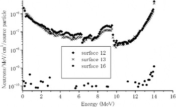
The neutron spectrum of each stage. Surface 12: a surface of 5th graphite end. S-13: surface of lithium ceramic ball layer end. S-16: a surface of concrete wall end.
At first, neutrons deposit their energy in the graphite blanket. They are stooped mainly in graphite blanket and heats up the graphite. Figure 4 shows the neutron flux of the depth of blanket and reinforced concrete shown in Figure 3. A neutron is well shielded by a concrete of 60 cm thickness in surface 16. After the graphite, surface 12 in Figure 5, in which neutron are well moderated. There is a lithium ceramic layer between surfaces 12 and 13; Neutrons are absorbed for tritium breeding. The thickness is not enough in this case. We may set lithium ceramic layer between the first wall and first layer of graphite, in the next step.
2.6. Energy balance
An energy balance of breakeven for this reactor is written as

and output of hydrogen energy is written as

where Q is a target gain and we take 20 to 30 in Table 3. EL is laser energy for one shot. Hn is an energy transfer rate of the neutron to the plasma in the target around the center of the reactor chamber. HDPC is an efficiency of direct power conversion efficiency and HLS is laser system efficiency. Hh is a conversion rate of neutron energy deposited in the blanket to hydrogen energy. In the case of Section 3, we take this rate as 0.67 for an ideal case. Here we take 0.65. The repetition rate R is 300, which strongly depends on a laser material and cooling rate. An economical estimation for the repetition rate may influence this. Eh is efficiency of a final output of hydrogen from thermal energy of the blanket. Table 2 shows typical parameters for these.
Blanket parameters

Energy flow of reactor

3. HYDROGEN PRODUCTION
Hydrogen production processes has been proposed many cases. Here we refer a typical case of GA-SI cycle as high temperature gas fission reactor. A typical hydrogen production is shown below.
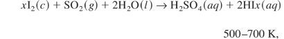
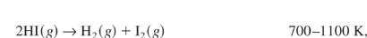
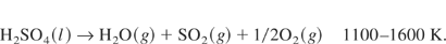
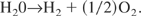
For example, we consider a surfer-iodine cycle. At first, xI2 (c), SO2 (g), and 2H2O(l) are mixed in the temperature to 700 K. Then HI and H2SO4 are generated through this thermo-chemical reaction of Eq. (1). They are separated from each other. Hydrogen heat them up to the high temperature, they react along Eqs. (2) and (3). Hydrogen is produced and again they come to be xI2 (c), SO2 (g), and 2H2O(l) as a cycle system. Finally, a total of this is written as
Tma is the maximum temperature of this process, Tmi is the minimum temperature of this process, Tma is determined by a neutron behavior in the blanket of the reactor and is estimated to be 1600 K. Tmin is determined from the temperature of thermal dissociation of H2SO4 in the process. The dissociation of HI is induced 700 K to 1100 K in this. Each process is composed of Carnot cycle and efficiency is given as

for the ideal case.
Pumps in this system are serious problems to operate this in such high temperature. To pump from lower temperature sides are considered but this is an important issue in actual reactor design.
4. SUMMARY
Summaries of this article are follows.
(1) A new approach for hydrogen production using IFE reactor is proposed. This reactor has magnetic coil which has similarity to mirror machine of magnetic confinement fusion. This magnetic field separates charged particles and neutron besides protecting the first wall and solid blanket. This mirror magnet also induces efficient direct conversion of charged particles through end loss.
(2) Such efficient direct conversion and efficient laser provide breakeven with low gain. This fact induces a smaller laser, which introduces a high repetition rate of a laser and efficient hydrogen production.
This proposal of the reactor is very primitive, and so there are many issues to be solved as follows: (1) The stability of plasma or charged particles in this mirror magnetic field should be analyzed. This influences the direct conversion efficiency and structure of the reactor. (2) Stresses by thermal and radiation effects should be estimated. The designs of the first wall and blanket are influenced by the stresses. (3) Material of the first wall for low activation is important. Low Z ceramics are candidate for this. A detail calculation is necessary. (4) Target gain around 20 is assumed. Gain from detail target physics, experiments, and design is the remaining issues to be solved. (5) There is a large effect for hydrogen economics by laser repetition rate and its efficiency. A ceramic laser indicates promising characteristics. We needs more progress for this.
Heavy ion may be used instead of laser. Repetition rate and other conditions for this reactor meet the heavy ion beam as same as laser. Mirror machine of magnetic confinement fusion device have been recognized to be an amplifier. For an example, injected neutral beams energy is amplified by a thermonuclear burning of heated plasma in mirror machine. A possibility of laser ignited target heating of the cold plasma confined in a mirror machine is conceivable, which amplifies the original inertial fusion energy. In this case, additional gain may be added to the target gain with a modified simple mirror magnet. These parameters are under investigation.


